Advertisement
D I S A S S E M B L Y
P R O C E D U R E
Disassembly Procedure
Please follow the information provided in this section to perform
the complete disassembly procedure of the notebook. Be sure to
use proper tools described before.
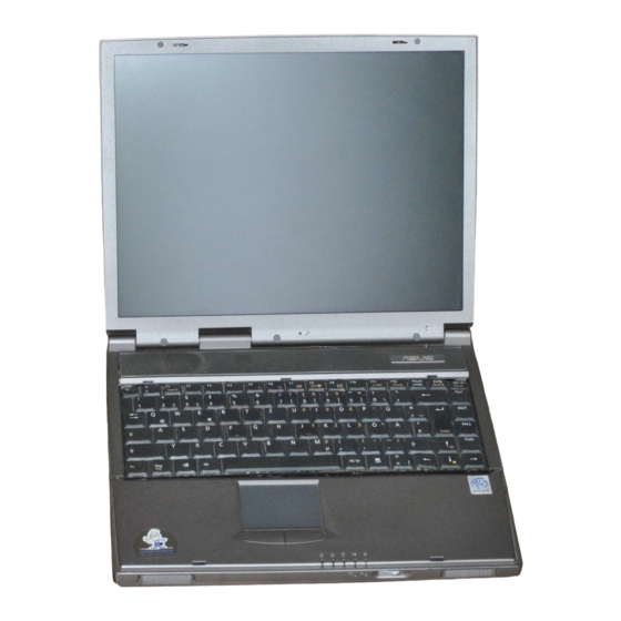
A
SUS L8400 B (ID1) Series Notebook consists of various modules. This
chapter describes the procedures for the complete notebook disassembly.
In addition, in between procedures, the detailed disassembly procedure of
individual modules will be provided for your service needs.
The disassembly procedure consists of the following steps:
Battery module
Keyboard, Memory and Function Cap
CPU Module
LCD Module
Palm Rest Module
HDD Module
Top Case Module
Bottom Case Module
Motherboard Module
FDD-Module
3 - 1
3 - 1
3
Chapter
Advertisement
Table of Contents

Related Manuals for Asus L8400


Summary of Contents for Asus L8400
-
Page 1: Disassembly Procedure
Be sure to use proper tools described before. SUS L8400 B (ID1) Series Notebook consists of various modules. This chapter describes the procedures for the complete notebook disassembly. In addition, in between procedures, the detailed disassembly procedure of individual modules will be provided for your service needs. -
Page 2: Battery Module
D I S A S S E M B L Y P R O C E D U R E Battery module B A T T E R Y The illustration below shows how to remove the battery module. 1. Turn the notebook over. Unlock and hold the latch (no.1), and firmly slide the other latch (no.2) to the top and remove the battery. - Page 3 The keyboard cable is still attached. Removing Memory module The L8400 B (ID1) Series Notebook comes standard with 64MB of RAM onboard. M E M O R Y There is one expansion SODIMM socket for you to upgrade the total memory up to...
- Page 4 D I S A S S E M B L Y P R O C E D U R E 5. Finally the keyboard plate can be removed from the notebook. 2. Cable out 1. Unlock 1. Unlock 3. Lock 3.
-
Page 5: Cpu Module
D I S A S S E M B L Y P R O C E D U R E CPU Module C P U The illustrations below show how to remove the CPU module from the notebook. Please do not disassemble the module. Removing CPU C P U 1. - Page 6 D I S A S S E M B L Y P R O C E D U R E No.2 No.1 Second, the AMP socket. 5. Unlock the CPU socket (no. 1) with a AMP CPU socket tool, 6. Turn the non-removable screw here in counter-clockwise direction until you hear the click to loosen the CPU.
- Page 7 D I S A S S E M B L Y P R O C E D U R E 7. Use the CPU vacuum to “suck up” the CPU and lift the CPU away. (no. 2). 3 - 7 7...
-
Page 8: Lcd Module
D I S A S S E M B L Y P R O C E D U R E LCD Module L C D The illustrations below show how to remove and disassemble the LCD module. The module contains LCD panel, invert, LCD hinge bracket, hinge cover, LCD front cover and LCD bottom case. - Page 9 D I S A S S E M B L Y P R O C E D U R E 4. Lift straight up the LCD panel from the system. Disassembling LCD Module L C D D I S - 1.
- Page 10 D I S A S S E M B L Y P R O C E D U R E 3 - 10...
- Page 11 D I S A S S E M B L Y P R O C E D U R E Palm Rest Module P A L M R E S T The illustrations below show how to remove the palm rest module from the notebook. M O D U L E Removing Palm Rest Module P A L M...
- Page 12 D I S A S S E M B L Y P R O C E D U R E pair or tweezers.3) Lock the connector (no. 3) again to avoid possible breakage. 4) Finally the keyboard plate can be removed from the notebook. 2.
-
Page 13: Hdd Module
D I S A S S E M B L Y P R O C E D U R E HDD Module H D D M O D U L E The illustrations below show how to remove the HDD module from the notebook. Removing HDD Module H D D M O D U L E... - Page 14 D I S A S S E M B L Y P R O C E D U R E Top Case Module T O P C A S E The illustrations below show how to disassemble and remove the top case module of M O D U L E the notebook.
- Page 15 D I S A S S E M B L Y P R O C E D U R E 3. Remove 2 screws (no.1, M2.5*8L(B)B-NI) and 1 screw (no.2, M2.5*5L(K)W-NI) to separate the top case to the bottom case. No.2 No.1 4.
- Page 16 D I S A S S E M B L Y P R O C E D U R E Disassembling System Frame S Y S T E M Remove 4 screws (no.1, M2*2.5L(K) B-NI) from the bottom of the top case F R A M E module.
- Page 17 D I S A S S E M B L Y P R O C E D U R E No.1 3 - 17...
- Page 18 D I S A S S E M B L Y P R O C E D U R E Bottom Case Module B O T T O M The illustrations below show how to disassemble and remove the bottom case module C A S E of the notebook.
- Page 19 D I S A S S E M B L Y P R O C E D U R E Removing Charge Board C H A R G E 1. Remove the Charge board (no.4). B O A R D 2.
- Page 20 D I S A S S E M B L Y P R O C E D U R E 2. Cable out 1. Unlock 1. Unlock 3. Lock 3. Lock 3 - 20...
- Page 21 D I S A S S E M B L Y P R O C E D U R E Motherboard Module M / B The illustrations below show how to disassemble and remove the motherboard module of the notebook. The module contains the motherboard itself, HDD/CD/FDD board, MB shielding bracket, FDD module and PCMCIA box..
- Page 22 D I S A S S E M B L Y P R O C E D U R E No.1 2. Lift up the PCMCIA box (no.1) from the motherboard. 3. Remove 6 hex screws (no.1, HEX 5mm) from the back of the motherboard with a spacer screw driver and 2 lock screws for docking port (no.2, HDR-E14LMY-SL-02C) with a single-slotted screw driver.
- Page 23 D I S A S S E M B L Y P R O C E D U R E 3 - 23...
-
Page 24: Fdd Module
D I S A S S E M B L Y P R O C E D U R E FDD Module F D D M O D U L E The illustrations below show how to disassemble the FDD module. Removing FDD module F D D M O D U L E... - Page 25 D I S A S S E M B L Y P R O C E D U R E 3 - 25...
Need help?
Do you have a question about the L8400 and is the answer not in the manual?
Questions and answers