
Related Manuals for Gigabyte GA-M720-ES3


Summary of Contents for Gigabyte GA-M720-ES3
- Page 1 GA-M720-ES3 AM2+/AM2 socket motherboard for AMD Phenom II processor/AMD Phenom processor/ AMD Athlon II processor/AMD Athlon processor/ AMD Sempron processor User's Manual Rev. 1001 12ME-M720ES3-1001R...
-
Page 3: Identifying Your Motherboard Revision
GIGABYTE's prior written permission. Documentation Classifications In order to assist in the use of this product, GIGABYTE provides the following types of documentations: For quick set-up of the product, read the Quick Installation Guide included with the product. -
Page 4: Table Of Contents
Table of Contents Box Contents ......................... 6 Optional Items......................... 6 GA-M720-ES3 Motherboard Layout ................7 Block Diagram........................ 8 Chapter 1 Hardware Installation ..................9 Installation Precautions ..................9 Product Specifications ..................10 Installing the CPU and CPU Cooler .............. 12 1-3-1 Installing the CPU .................... - Page 5 Chapter 3 Drivers Installation ..................55 Installing Chipset Drivers ................55 Software Applications ..................56 Driver CD Information ..................56 Hardware Information ..................57 Contact Us ..................... 57 Chapter 4 Unique Features ..................59 Xpress Recovery2 ..................59 BIOS Update Utilities ..................62 4-2-1 Updating the BIOS with the Q-Flash Utility ............
-
Page 6: Box Contents
Box Contents GA-M720-ES3 motherboard Motherboard driver disk User's Manual Quick Installation Guide One IDE cable Two SATA 3Gb/s cables I/O Shield • The box contents above are for reference only and the actual items shall depend on product package you obtain. -
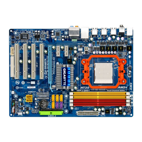
Page 7: Ga-M720-Es3 Motherboard Layout
GA-M720-ES3 Motherboard Layout KB_MS RCA_SPDIF R_USB Socket AM2 R_USB R_USB ATX_12V USB_LAN AUDIO CPU_FAN PCIEX1_1 SATA2_5 NVIDIA ® SATA2_4 nForce 720D PCIEX1_2 SATA2_2 SATA2_1 RTL8111C GA-M720-ES3 SATA2_0 PCIEX16 SATA2_3 PCI1 CODEC BATTERY PCI2 PCI3 TSB43AB23 IT8720 PCI4 SYS_FAN2 M_BIOS B_BIOS... -
Page 8: Block Diagram
Block Diagram CPU CLK+/-(200 MHz) PCIe CLK AM3/AM2+/AM2 (100 MHz) DDR2 1200 /1066/800 MHz (Note) Dual Channel Memory Hyper Transport 3.0 1 PCI Express x16 PCI Express x16 12 USB Ports PCI Express x1 Bus NVIDIA ® nForce 720D RTL8111C 6 SATA 3Gb/s PCIe CLK (100 MHz) -
Page 9: Chapter 1 Hardware Installation
Chapter 1 Hardware Installation Installation Precautions The motherboard contains numerous delicate electronic circuits and components which can become damaged as a result of electrostatic discharge (ESD). Prior to installation, carefully read the user's manual and follow these procedures: Prior to installation, do not remove or break motherboard S/N (Serial Number) sticker or •... -
Page 10: Product Specifications
AMD Phenom II processor/AMD Phenom processor/ AMD Athlon II processor/AMD Athlon processor/ AMD Sempron processor (Go to GIGABYTE's website for the latest CPU support list.) Hyper Transport Bus 5200/2000 MT/s Chipset NVIDIA nForce 720D chipset ® Memory 4 x 1.8V DDR2 DIMM sockets supporting up to 16 GB of system memory... - Page 11 Internal Connectors 2 x USB 2.0/1.1 headers 1 x serial port header 1 x power LED header 1 x chassis intrusion header 1 x clearing CMOS switch Back Panel 1 x PS/2 keyboard port Connectors ...
-
Page 12: Installing The Cpu And Cpu Cooler
Read the following guidelines before you begin to install the CPU: • Make sure that the motherboard supports the CPU. (Go to GIGABYTE's website for the latest CPU support list.) • Always turn off the computer and unplug the power cord from the power outlet before installing the CPU to prevent hardware damage. - Page 13 B. Follow the steps below to correctly install the CPU into the motherboard CPU socket. Before installing the CPU, make sure to turn off the computer and unplug the power cord from the power outlet to prevent damage to the CPU. CPU Socket Locking Lever Step 1:...
-
Page 14: Installing The Cpu Cooler
1-3-2 Installing the CPU Cooler Follow the steps below to correctly install the CPU cooler on the CPU. (The following procedure uses the GIGABYTE cooler as the example.) Step 1: Step 2: Apply an even and thin layer of thermal grease Place the CPU cooler on the CPU. -
Page 15: Installing The Memory
• Make sure that the motherboard supports the memory. It is recommended that memory of the same capacity, brand, speed, and chips be used. (Go to GIGABYTE's website for the latest memory support list.) • Always turn off the computer and unplug the power cord from the power outlet before installing the memory to prevent hardware damage. -
Page 16: Installing A Memory
Step 2: The clips at both ends of the socket will snap into place when the memory module is securely inserted. GA-M720-ES3 Motherboard - 16 -... -
Page 17: Installing An Expansion Card
Installing an Expansion Card Read the following guidelines before you begin to install an expansion card: • Make sure the motherboard supports the expansion card. Carefully read the manual that came with your expansion card. • Always turn off the computer and unplug the power cord from the power outlet before installing an expansion card to prevent hardware damage. -
Page 18: Back Panel Connectors
• When removing the cable, pull it straight out from the connector. Do not rock it side to side to prevent an electrical short inside the cable connector. GA-M720-ES3 Motherboard - 18 -... - Page 19 Center/Subwoofer Speaker Out Jack (Orange) Use this audio jack to connect center/subwoofer speakers in a 5.1/7.1-channel audio configuration. Rear Speaker Out Jack (Black) Use this audio jack to connect rear speakers in a 4/5.1/7.1-channel audio configuration. Side Speaker Out Jack (Gray) Use this audio jack to connect side speakers in a 7.1-channel audio configuration.
-
Page 20: Internal Connectors
• After installing the device and before turning on the computer, make sure the device cable has been securely attached to the connector on the motherboard. GA-M720-ES3 Motherboard - 20 -... - Page 21 1/2) ATX_12V/ATX (2x2 12V Power Connector and 2x12 Main Power Connector) With the use of the power connector, the power supply can supply enough stable power to all the components on the motherboard. Before connecting the power connector, first make sure the power supply is turned off and all devices are properly installed.
- Page 22 1 of the connector and the floppy disk drive cable. The pin 1 of the cable is typically designated by a stripe of different color. For purchasing the optional floppy disk drive cable, please contact the local dealer. GA-M720-ES3 Motherboard - 22 -...
- Page 23 7) IDE (IDE Connector) The IDE connector supports up to two IDE devices such as hard drives and optical drives. Before attaching the IDE cable, locate the foolproof groove on the connector. If you wish to connect two IDE devices, remember to set the jumpers and the cabling according to the role of the IDE devices (for example, master or slave).
-
Page 24: System Power Led Header
• When installing the battery, note the orientation of the positive side (+) and the negative side (-) of the battery (the positive side should face up). • Used batteries must be handled in accordance with local environmental regulations. GA-M720-ES3 Motherboard - 24 -... -
Page 25: F_Panel
11) F_PANEL (Front Panel Header) Connect the power switch, reset switch, speaker and system status indicator on the chassis front panel to this header according to the pin assignments below. Note the positive and negative pins before connecting the cables. Message/Power/ Power Sleep LED... -
Page 26: Cd In Connector
13) CD_IN (CD In Connector) You may connect the audio cable that came with your optical drive to the header. Pin No. Definition CD-L CD-R GA-M720-ES3 Motherboard - 26 -... - Page 27 14) SPDIF_O (S/PDIF Out Header) This header supports digital S/PDIF out and connects a S/PDIF digital audio cable (provided by expansion cards) for digital audio output from your motherboard to certain expansion cards like graphics cards and sound cards. For example, some graphics cards may require you to use a S/PDIF digital audio cable for digital audio output from your motherboard to your graphics card if you wish to connect an HDMI display to the graphics card and have digital audio output from the HDMI display at the same time.
- Page 28 17) CI (Chassis Intrusion Header) This motherboard provides a chassis detection feature that detects if the chassis cover has been removed. This function requires a chassis with chassis intrusion detection design. Pin No. Definition Signal GA-M720-ES3 Motherboard - 28 -...
-
Page 29: Clearing Cmos Jumper
18) CLR_CMOS (Clearing CMOS Jumper) Use this jumper to clear the CMOS values (e.g. date information and BIOS configurations) and reset the CMOS values to factory defaults. To clear the CMOS values, place a jumper cap on the two pins to temporarily short the two pins or use a metal object like a screwdriver to touch the two pins for a few seconds. - Page 30 GA-M720-ES3 Motherboard - 30 -...
-
Page 31: Chapter 2 Bios Setup
To see more advanced BIOS Setup menu options, you can press <Ctrl> + <F1> in the main menu of the BIOS Setup program. To upgrade the BIOS, use either the GIGABYTE Q-Flash or @BIOS utility. Q-Flash allows the user to quickly and easily upgrade or back up BIOS without entering the •... -
Page 32: Startup Screen
BIOS Setup settings. You can access Boot Menu again to change the first boot device setting as needed. <END>: Q-FLASH Press the <End> key to access the Q-Flash utility directly without having to enter BIOS Setup first. GA-M720-ES3 Motherboard - 32 -... -
Page 33: The Main Menu
The Main Menu Once you enter the BIOS Setup program, the Main Menu (as shown below) appears on the screen. Use arrow keys to move among the items and press <Enter> to accept or enter a sub-menu. (Sample BIOS Version:E3c) CMOS Setup Utility-Copyright (C) 1984-2009 Award Software ... - Page 34 Exit Without Saving Abandon all changes and the previous settings remain in effect. Pressing <Y> to the confirmation message will exit BIOS Setup. (Pressing <Esc> can also carry out this task.) GA-M720-ES3 Motherboard - 34 -...
-
Page 35: Mb Intelligent Tweaker(M.i.t.)
MB Intelligent Tweaker(M.I.T.) CMOS Setup Utility-Copyright (C) 1984-2009 Award Software MB Intelligent Tweaker(M.I.T.) Advanced Clock Calibration Item Help [Press Enter] CPU Frequency [200] Menu Level HT Link Frequency [Auto] PCIE Clock [100] CPU Clock Ratio [Auto] (Note) CPU NorthBridge Freq. [Auto] Robust Graphics Booster [Disabled]... - Page 36 Allows you to alter the core clock for the graphics chip and is configurable only if the Robust Graphics Booster option is set to Enabled. The core clock can be increased by 1% ~ 50%. GA-M720-ES3 Motherboard - 36 -...
-
Page 37: Dram Configuration
DRAM Configuration CMOS Setup Utility-Copyright (C) 1984-2009 Award Software DRAM Configuration Item Help SLI-Ready Memory [Disabled] Menu Level Set Memory Clock [Auto] x Memory Clock X3.33 667Mhz DDRII Timing Items [Auto] Auto x CAS# latency Auto x RAS to CAS R/W Delay Auto x Row Precharge Time Auto... - Page 38 Options are: 75ns, 105ns, 127.5ns, 195ns, 327.5ns. Write Recovery Time Options are: Auto (default), 3T~6T. Precharge Time Options are: Auto (default), 2T, 3T. Row Cycle Time Options are: Auto (default), 11T~26T. RAS to RAS Delay Options are: Auto (default), 2T~5T. GA-M720-ES3 Motherboard - 38 -...
- Page 39 ******** System Voltage Optimized ******** System Voltage Control Determines whether to manually set the system voltages. Auto lets BIOS automatically set the system voltages as required. Manual allows all voltage control items below to be configurable. (Default: Auto) DDR2 Voltage Control Allows you to set memory voltage.
-
Page 40: Standard Cmos Features
If no IDE/SATA devices are used, set this item to None so the system will skip the detection of the device during the POST for faster system startup. Access Mode Sets the hard drive access mode. Options are: Auto (default), Large. GA-M720-ES3 Motherboard - 40 -... - Page 41 The following fields display your hard drive specifications. If you wish to enter the parameters manually, refer to the information on the hard drive. Capacity Approximate capacity of the currently installed hard drive. Cylinder Number of cylinders. Head Number of heads. Precomp Write precompensation cylinder.
-
Page 42: Advanced Bios Features
<Enter> to accept. Options are: Floppy, LS120, Hard Disk, CDROM, ZIP, USB-FDD, USB-ZIP, USB-CDROM, USB-HDD, Legacy LAN, Disabled. (Note) This item is present only if you install a CPU that supports this feature. GA-M720-ES3 Motherboard - 42 -... - Page 43 (Default: Disabled) Full Screen LOGO Show Allows you to determine whether to display the GIGABYTE Logo at system startup. Disabled displays normal POST message. (Default: Enabled) Backup BIOS Image to HDD Allows the system to copy the BIOS image file to the hard drive.
-
Page 44: Integrated Peripherals
Disabled. Onboard LAN Control Enables or disables the onboard LAN function. (Default: Enabled) If you wish to install a 3rd party add-in network card instead of using the onboard LAN, set this item to Disabled. GA-M720-ES3 Motherboard - 44 -... - Page 45 SMART LAN (LAN Cable Diagnostic Function) CMOS Setup Utility-Copyright (C) 1984-2009 Award Software SMART LAN Start detecting at Port..Item Help Menu Level Part1-2 Status = Open / Length Part3-6 Status = Open / Length Part4-5 Status = Open / Length Part7-8 Status = Open / Length...
- Page 46 USB Mouse Support Allows USB mouse to be used in MS-DOS. (Default: Disabled) Legacy USB storage detect Determines whether to detect USB storage devices, including USB flash drives and USB hard drives during the POST. (Default: Enabled) GA-M720-ES3 Motherboard - 46 -...
-
Page 47: Power Management Setup
Power Management Setup CMOS Setup Utility-Copyright (C) 1984-2009 Award Software Power Management Setup ACPI Suspend Type [S3(STR)] Item Help Soft-Off by Power button [Instant-off] Menu Level PME Event Wake Up [Enabled] Modem Ring On [Enabled] USB Resume from Suspend [Enabled] Power-On by Alarm [Disabled] x Date (of Month) - Page 48 The system is turned on upon the return of the AC power. Memory The system returns to its last known awake state upon the return of the AC power. (Note) Supported on Windows Vista operating system only. ® ® GA-M720-ES3 Motherboard - 48 -...
-
Page 49: Pnp/Pci Configurations
PnP/PCI Configurations CMOS Setup Utility-Copyright (C) 1984-2009 Award Software PnP/PCI Configurations PCI1 IRQ Assignment [Auto] Item Help PCI2 IRQ Assignment [Auto] Menu Level PCI3 IRQ Assignment [Auto] PCI4 IRQ Assignment [Auto] : Move Enter: Select +/-/PU/PD: Value F10: Save ESC: Exit F1: General Help F5: Previous Values F6: Fail-Safe Defaults... -
Page 50: Pc Health Status
Reset Case Open Status Keeps or clears the record of previous chassis intrusion status. Enabled clears the record of previous chassis intrusion status and the Case Opened field will show "No" at next boot. (Default: Disabled) GA-M720-ES3 Motherboard - 50 -... - Page 51 Case Opened Displays the detection status of the chassis intrusion detection device attached to the motherboard CI header. If the system chassis cover is removed, this field will show "Yes", otherwise it will show "No". To clear the chassis intrusion status record, set Reset Case Open Status to Enabled, save the settings to CMOS, and then restart your system.
-
Page 52: Load Fail-Safe Defaults
Press <Enter> on this item and then press the <Y> key to load the optimal BIOS default settings. The BIOS defaults settings helps the system to operate in optimum state. Always load the Optimized defaults after updating the BIOS or after clearing the CMOS values. GA-M720-ES3 Motherboard - 52 -... -
Page 53: Set Supervisor/User Password
2-12 Set Supervisor/User Password CMOS Setup Utility-Copyright (C) 1984-2009 Award Software MB Intelligent Tweaker(M.I.T.) Load Fail-Safe Defaults Standard CMOS Features Load Optimized Defaults Advanced BIOS Features Set Supervisor Password Integrated Peripherals Set User Password Power Management Setup Enter Password: Save &... -
Page 54: Save & Exit Setup
Press <Enter> on this item and press the <Y> key. This exits the BIOS Setup without saving the changes made in BIOS Setup to the CMOS. Press <N> or <Esc> to return to the BIOS Setup Main Menu. GA-M720-ES3 Motherboard - 54 -... -
Page 55: Chapter 3 Drivers Installation
Chapter 3 Drivers Installation • Before installing the drivers, first install the operating system. • After installing the operating system, insert the motherboard driver disk into your optical drive. The driver Autorun screen is automatically displayed which looks like that shown in the screen shot below. -
Page 56: Software Applications
Software Applications This page displays all the tools and applications that GIGABYTE develops and some free software. You may press the Install button following an item to install it. Driver CD Information This page provides information about the drivers, applications and tools in this driver disk. -
Page 57: Hardware Information
This page provides information about the hardware devices on this motherboard. Contact Us For the detailed contact information of the GIGABYTE Taiwan headquarter or worldwide branch offices, click the URL on this page to link to the GIGABYTE Website. - 57 -... - Page 58 GA-M720-ES3 Motherboard - 58 -...
-
Page 59: Chapter 4 Unique Features
Chapter 4 Unique Features Xpress Recovery2 Xpress Recovery2 is a utility that allows you to quickly compress and back up your system data and perform restoration of it. Supporting NTFS, FAT32, and FAT16 file systems, Xpress Recovery2 can back up data on PATA and SATA hard drives and restore it. Before You Begin: •... - Page 60 Xpress Recovery2 will automatically create a new partition to store the backup image file. Step 1: Step 2: Select BACKUP to start backing up your hard When finished, go to Disk Management to drive data. check disk allocation. GA-M720-ES3 Motherboard - 60 -...
- Page 61 D. Using the Restore Function in Xpress Recovery2 Select RESTORE to restore the backup to your hard drive in case the system breaks down. The RESTORE option will not be present if no backup is created before. E. Removing the Backup Step 1: Step 2: If you wish to remove the backup file, select...
-
Page 62: Bios Update Utilities
4-2-1 Updating the BIOS with the Q-Flash Utility A. Before You Begin: 1. From GIGABYTE's website, download the latest compressed BIOS update file that matches your motherboard model. 2. Extract the file and save the new BIOS file (e.g. M720ES3.F1) to your floppy disk, USB flash drive, or hard drive. - Page 63 B. Updating the BIOS When updating the BIOS, choose the location where the BIOS file is saved. The follow procedure assumes that you save the BIOS file to a floppy disk. Step 1: 1. Insert the floppy disk containing the BIOS file into the floppy disk drive. In the main menu of Q-Flash, use the up or down arrow key to select Update BIOS from Drive and press <Enter>.
- Page 64 Load Optimized Defaults Press <Y> to load BIOS defaults Step 6: Select Save & Exit Setup and then press <Y> to save settings to CMOS and exit BIOS Setup. The procedure is complete after the system restarts. GA-M720-ES3 Motherboard - 64 -...
-
Page 65: Updating The Bios With The @Bios Utility
BIOS or a system that is unable to start. 3. Do not use the G.O.M. (GIGABYTE Online Management) function when using @BIOS. 4. GIGABYTE product warranty does not cover any BIOS damage or system failure resulting from an inadequate BIOS flashing. -
Page 66: Easytune 6
EasyTune 6 GIGABYTE's EasyTune 6 is a simple and easy-to-use interface that allows users to fine-tune their system settings or do overclock/overvoltage in Windows environment. The user-friendly EasyTune 6 interface also includes tabbed pages for CPU and memory information, lettings users read their system- related information without the need to install additional software. -
Page 67: Easy Energy Saver
The Easy Energy Saver Interface A. Meter Mode In Meter Mode, GIGABYTE Easy Energy Saver shows how much power they have saved in a set period of time. Meter Mode - Button Information Table Button Description... - Page 68 (Note 4) The total amount of power saved will be recorded until re-activated when only the Easy Energy Saver is under the enable status, and power savings meter is unable to reset to zero. (Note 5) Easy Energy Saver Meter will automatically reset when the total power saving reaches 99999999 Watts. GA-M720-ES3 Motherboard - 68 -...
-
Page 69: Chapter 5 Appendix
Chapter 5 Appendix Configuring SATA Hard Drive(s) To configure SATA hard drive(s), follow the steps below: A. Install SATA hard drive(s) in your computer. B. Configure SATA controller mode in BIOS Setup. C . Configure a RAID array in RAID BIOS. (Note 1) D. - Page 70 The BIOS Setup menus described in this section may differ from the exact settings for your motherboard. The actual BIOS Setup menu options you will see shall depend on the motherboard you have and the BIOS version. GA-M720-ES3 Motherboard - 70 -...
- Page 71 C. Configuring RAID set in RAID BIOS Enter the RAID BIOS setup utility to configure a RAID array. For a non-RAID configuration, please skip this step and proceed to the installation of Windows operating system. Step 1: After the POST memory test begins and before the operating system boot begins, look for a message which says "Press F10 to enter RAID setup utility"...
- Page 72 [ ] Add 1.1.M ST3120026AS 111.79GB [Y] YES [N] NO [ ] Del ] Select [ESC] Quit [F6] Back [F7] Finish [TAB] Navigate [ [ENTER] Popup Figure 5 GA-M720-ES3 Motherboard - 72 -...
- Page 73 After that, the Array List screen appears, displaying the RAID array that you have created (Figure 6). (Note: BBS stands for BIOS Boot Specification. This indicates that the boot device is defined in the BIOS.) MediaShield BIOS Apr 25 2008 - Array List - Boot Status...
-
Page 74: Making A Sata Raid/Ahci Driver Diskette For Windows Xp
Use an alternative system and insert the motherboard driver disk. From your optical drive folder, double click the MENU.exe file in the BootDrv folder (Figure 3). A command prompt window will open similar to that in Figure 2. Figure 3 GA-M720-ES3 Motherboard - 74 -... -
Page 75: Installing The Sata Raid Driver And Operating System
5-1-3 Installing the SATA RAID Driver and Operating System With the SATA RAID driver diskette and correct BIOS settings, you are ready to install Windows operating system onto your hard drives. A. Installing Windows XP Step 1: Restart your system to boot from the Windows XP setup disk and press <F6> as soon as you see the message "Press F6 if you need to install a 3rd party SCSI or RAID driver"... - Page 76 For Windows Vista 64-bit, browse to the Vista64RAID folder (Figure 4). Method B: Insert the USB flash drive containing the driver files and browse to the Vista32RAID (for Windows Vista 32-bit) or Vista64RAID (for Windows Vista 64-bit) folder. Figure 4 GA-M720-ES3 Motherboard - 76 -...
- Page 77 Step 3: When a screen as shown in Figure 5 appears, select NVIDIA nForce RAID Controller and press Next. Figure 5 Step 4: After the driver is loaded, the screen will show the RAID hard drive. Select the RAID hard drive onto which you want to install the operating system and then press Next to continue the OS installation (Figure 6).
- Page 78 Select the array to rebuild and click Next. Select a drive to add to the array and click Next. Step 5: Step 6: Click Finish to start the rebuilding process. The rebuilding progress is displayed in the View Storage Configuration sub-menu. GA-M720-ES3 Motherboard - 78 -...
-
Page 79: Configuring Audio Input And Output
Configuring Audio Input and Output 5-2-1 Configuring 2/4/5.1/7.1-Channel Audio The motherboard provides six audio jacks on the back panel which support 2/4/5.1/7.1 -channel (Note) audio. The picture to the right shows the default Center/Subwoofer Line In Speaker Out audio jack assignments. Front Speaker Out The integrated HD (High Definition) audio provides Rear Speaker Out... - Page 80 Click Device advanced settings on the top right cor- ner on the Speaker Configuration tab to open the Device advanced settings dialog box. Select the Mute the rear output device, when a front headphone plugged in check box. Click OK to complete. GA-M720-ES3 Motherboard - 80 -...
-
Page 81: Configuring S/Pdif Out
5-2-2 Configuring S/PDIF Out S/PDIF Out: The S/PDIF Out jacks can transmit audio signals to an external decoder for decoding to get the best audio quality. 1. Connecting a S/PDIF Out Cable S/PDIF Optical Cable S/PDIF Coaxial Cable Connect a S/PDIF coaxial cable or a S/PDIF optical cable (either one) to an external decoder for transmitting the S/PDIF digital audio signals. -
Page 82: Configuring Microphone Recording
It is recommended that you set the volumes at a middle level. If you want to change the current sound input default device to microphone, right-click on Microphone and select Set Default Device. GA-M720-ES3 Motherboard - 82 -... - Page 83 Step 4: To raise the recording and playback volume for the microphone, click the Microphone Boost icon on the right of the Recording Volume slider and set the Microphone Boost level. Step 5: After completing the settings above, click Start, point to Programs, point to Accessories, and then click Sound Recorder to begin the sound recording.
-
Page 84: Using The Sound Recorder
3. To stop recording audio, click the Stop Recording button Be sure to save the recorded audio file upon completion. B. Playing the Recorded Sound: You can play your recording in a digital media player program that supports your audio file format. GA-M720-ES3 Motherboard - 84 -... -
Page 85: Troubleshooting
5-3-1 Frequently Asked Questions To read more FAQs for your motherboard, please go to the Support&Downloads\Motherboard\FAQ page on GIGABYTE's website. Q: In the BIOS Setup program, why are some BIOS options missing? A: Some advanced options are hidden in the BIOS Setup program. Press <Delete> to enter BIOS Setup during the POST. -
Page 86: Troubleshooting Procedure
Insert the graphics card. Connect the ATX main power cable and the 12V power cable. Turn on the power to start the computer. Make sure the graphics card is securely seated in the expansion slot and power connectors are firmly attached. (Continued...) GA-M720-ES3 Motherboard - 86 -... - Page 87 The power supply, When the computer is turned on, is the CPU cooler running? CPU or CPU socket might fail. The problem is verified and solved. The graphics card, expansion slot, or Check if there is display on your monitor. monitor might fail.
-
Page 88: Regulatory Statements
"end of life" product. Restriction of Hazardous Substances (RoHS) Directive Statement GIGABYTE products have not intended to add and safe from hazardous substances (Cd, Pb, Hg, Cr+6, PBDE and PBB). The parts and components have been carefully selected to meet RoHS requirement. - Page 89 Finally, we suggest that you practice other environmentally friendly actions by understanding and using the energy-saving features of this product (where applicable), recycling the inner and outer packaging (including shipping containers) this product was delivered in, and by disposing of or recycling used batteries properly.
- Page 90 GA-M720-ES3 Motherboard - 90 -...
- Page 91 - 91 - Appendix...
- Page 92 GA-M720-ES3 Motherboard - 92 -...
- Page 93 - 93 - Appendix...
- Page 94 GA-M720-ES3 Motherboard - 94 -...
- Page 95 TEL: +86-24-83992901 GIGA-BYTE SINGAPORE PTE. LTD. - Singapore FAX: +86-24-83992909 WEB address : http://www.gigabyte.sg GIGABYTE TECHNOLOGY (INDIA) LIMITED - India Thailand WEB address : http://www.gigabyte.in ...
- Page 96 WEB address : http://www.giga-byte.kz Czech Republic You may go to the GIGABYTE website, select your language WEB address : http://www.gigabyte.cz in the language list on the top right corner of the website. GIGABYTE Global Service System...
Need help?
Do you have a question about the GA-M720-ES3 and is the answer not in the manual?
Questions and answers