ASROCK Z87 Extreme6 Specifications
Quick installation guide
Hide thumbs
Also See for Z87 Extreme6:
- User manual (115 pages) ,
- Installation and configuration manual (20 pages) ,
- Installation manual (4 pages)
Table of Contents
Advertisement
Available languages
Available languages
Quick Links
Version 1.0
Published May 2013
Copyright©2013 ASRock INC. All rights reserved.
Copyright Notice:
No part of this documentation may be reproduced, transcribed, transmitted, or
translated in any language, in any form or by any means, except duplication of
documentation by the purchaser for backup purpose, without written consent of
ASRock Inc.
Products and corporate names appearing in this documentation may or may not
be registered trademarks or copyrights of their respective companies, and are used
only for identification or explanation and to the owners' benefit, without intent to
infringe.
Disclaimer:
Specifications and information contained in this documentation are furnished for
informational use only and subject to change without notice, and should not be
constructed as a commitment by ASRock. ASRock assumes no responsibility for
any errors or omissions that may appear in this documentation.
With respect to the contents of this documentation, ASRock does not provide
warranty of any kind, either expressed or implied, including but not limited to
the implied warranties or conditions of merchantability or fitness for a particular
purpose.
In no event shall ASRock, its directors, officers, employees, or agents be liable for
any indirect, special, incidental, or consequential damages (including damages for
loss of profits, loss of business, loss of data, interruption of business and the like),
even if ASRock has been advised of the possibility of such damages arising from any
defect or error in the documentation or product.
This device complies with Part 15 of the FCC Rules. Operation is subject to the following
two conditions:
(1) this device may not cause harmful interference, and
(2) this device must accept any interference received, including interference that
may cause undesired operation.
CALIFORNIA, USA ONLY
The Lithium battery adopted on this motherboard contains Perchlorate, a toxic substance
controlled in Perchlorate Best Management Practices (BMP) regulations passed by the
California Legislature. When you discard the Lithium battery in California, USA, please
follow the related regulations in advance.
"Perchlorate Material-special handling may apply, see www.dtsc.ca.gov/hazardouswaste/
perchlorate"
ASRock Website: http://www.asrock.com
Advertisement
Table of Contents

Subscribe to Our Youtube Channel
Related Manuals for ASROCK Z87 Extreme6


Summary of Contents for ASROCK Z87 Extreme6
-
Page 1: Copyright Notice
(including damages for loss of profits, loss of business, loss of data, interruption of business and the like), even if ASRock has been advised of the possibility of such damages arising from any defect or error in the documentation or product. - Page 2 The terms HDMI™ and HDMI High-Definition Multimedia Interface, and the HDMI logo are trademarks or registered trademarks of HDMI Licensing LLC in the United States and other countries. Manufactured under license under U.S. Patent Nos: 5,956,674; 5,974,380; 6,487,535; 7,003,467 & other U.S. and worldwide patents issued & pending. DTS, the Symbol, & DTS and the Symbol together is a registered trademark &...
-
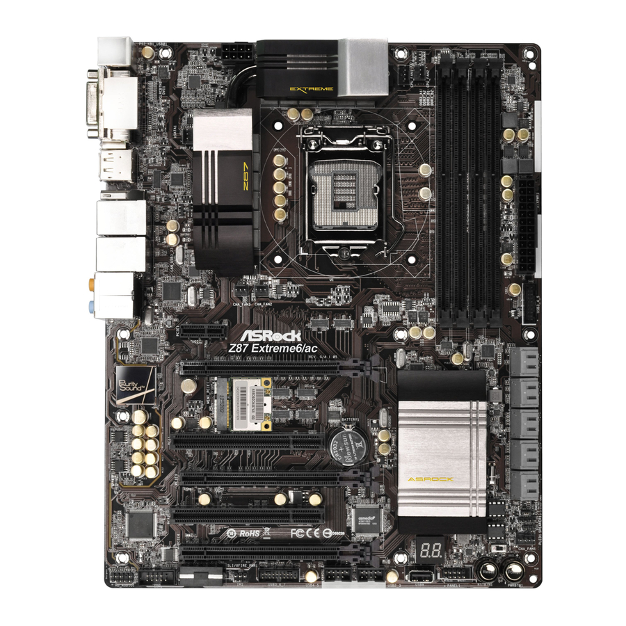
Page 3: Motherboard Layout
Z87 Extreme6/ac / Z87 Extreme6 Motherboard Layout Z87 Extreme6/ac ATX12V1 CPU_FAN2 CPU_FAN1 CMOS PWR_FAN1 HDMI_IN1 USB 3.0 Top: T: USB0 RJ-45 B: USB1 USB 3.0 Top: T: USB2 RJ-45 B: USB3 CHA_FAN3 CHA_FAN2 PCIE1 Z87 Extreme6/ac PCIE2 Purity Sound Intel... - Page 4 Z87 Extreme6 ATX12V1 CPU_FAN2 CPU_FAN1 CMOS PWR_FAN1 HDMI_IN1 USB 3.0 Top: T: USB0 RJ-45 B: USB1 USB 3.0 Top: T: USB2 RJ-45 B: USB3 CHA_FAN3 CHA_FAN2 PCIE1 Z87 Extreme6 PCIE2 Purity Sound Intel PCI1 CMOS Battery PCIE3 BIOS_B_LED 64Mb PCI2...
- Page 5 Z87 Extreme6/ac / Z87 Extreme6 No. Description Power Fan Connector (PWR_FAN1) ATX 12V Power Connector (ATX12V1) CPU Fan Connector (CPU_FAN1) CPU Fan Connector (CPU_FAN2) 2 x 240-pin DDR3 DIMM Slots (DDR3_A1, DDR3_B1) 2 x 240-pin DDR3 DIMM Slots (DDR3_A2, DDR3_B2) ATX Power Connector (ATXPWR1) USB 3.0 Header (USB3_4_5)
- Page 6 I/O Panel No. Description No. Description USB 2.0 Ports (USB01) Optical SPDIF Out Port DVI-I Port USB 3.0 Ports (USB3_23) Display Port (ASMedia Hub) LAN RJ-45 Port (Intel® I217V)* USB 3.0 Ports (USB3_01) LAN RJ-45 Port (Intel® I211AT)* (ASMedia Hub) Central / Bass (Orange) HDMI-In Port Rear Speaker (Black)
- Page 7 Z87 Extreme6/ac / Z87 Extreme6 * There are two LEDs on each LAN port. Please refer to the table below for the LAN port LED indications. ACT/LINK LED SPEED LED LAN Port Activity / Link LED Speed LED Status Description...
-
Page 8: Chapter 1 Introduction
If you require technical support related to this mother- board, please visit our website for specific information about the model you are using. You may find the latest VGA cards and CPU support list on ASRock’s website as well. ASRock website http://www.asrock.com. -
Page 9: Specifications
• ATX Form Factor • Premium Gold Capacitor design (100% Japan-made high- quality Conductive Polymer Capacitors) A-Style • Home Cloud • 802.11ac WiFi (for Z87 Extreme6/ac only ) • Purity Sound • HDMI-In • Socket LGA1150 to support 4 Gen Intel® Core Processor • Digi Power Design... - Page 10 Graphics • Intel® HD Graphics Built-in Visuals and the VGA outputs can be supported only with processors which are GPU integrated. • Supports Intel® HD Graphics Built-in Visuals : Intel® Quick Sync Video with AVC, MVC (S3D) and MPEG-2 Full HW Encode1, Intel®...
- Page 11 Z87 Extreme6/ac / Z87 Extreme6 • Gigabit LAN 10/100/1000 Mb/s • 1 x Giga PHY Intel® I217V, 1 x GigaLAN Intel® I211AT • Supports Intel® Remote Wake Technology (on Intel® I217V) • Supports Wake-On-LAN • Supports Dual LAN with Teaming • Supports Energy Efficient Ethernet 802.3az...
- Page 12 Storage • 6 x SATA3 6.0 Gb/s connectors by Intel® Z87, support RAID (RAID 0, RAID 1, RAID 5, RAID 10, Intel Rapid Storage Technology 12 and Intel Smart Response Technology), NCQ, AHCI and “Hot Plug” • 4 x SATA3 6.0 Gb/s connectors by ASMedia ASM1061, sup- port NCQ, AHCI and “Hot Plug”...
- Page 13 Due to limitation, the actual memory size may be less than 4GB for the reservation for sys- tem usage under Windows® 32-bit operating systems. Windows® 64-bit operating systems do not have such limitations. You can use ASRock XFast RAM to utilize the memory that Windows® cannot use.
-
Page 14: Unique Features
LED, FAN-Tastic Tuning, OC Tweaker and a whole lot more. ASRock Instant Flash ASRock Instant Flash is a BIOS flash utility embedded in Flash ROM. This conve- nient BIOS update tool allows you to update the system BIOS in a few clicks without preparing an additional floppy diskette or other complicated flash utility. - Page 15 And it also boosts the speed of Adobe Photoshop 5 times faster. Another advantage of ASRock XFast RAM is that it reduces the frequency of accessing your SSDs or HDDs in order to extend their lifespan.
- Page 16 Windows® 8 brings the ultimate boot up experience. The lightning boot up speed makes it hard to access the UEFI setup. ASRock Restart to UEFI allows users to enter the UEFI automatically when turning on the PC. By enabling this function, the PC will enter the UEFI directly after you restart.
- Page 17 ASRock Distortion-Free Slot ASRock's new pin design for the memory slots and PCIe slots may appear to be the same as former designs, but actually effectively reduces distortion and promotes performance, because we strive for perfection even in the most trivial details.
-
Page 18: Wifi-802.11N Module And Asrock Wifi 2.4Ghz Antenna (For Z87 Extreme6/Ac Only )
1.4 WiFi-802.11n Module and ASRock WiFi 2.4GHz Antenna (for Z87 Extreme6/ac only ) WiFi + BT Module This motherboard comes with an exclusive WiFi 802.11 a/b/g/n/ac + BT v4.0 module that offers support for WiFi 802.11 a/b/g/n/ac connectivity standards and Bluetooth v4.0. - Page 19 Z87 Extreme6/ac / Z87 Extreme6 Installing the SMA Wi-Fi Antenna Cables Step 1 Prepare the SMA Wi-Fi Antenna Cables that come with the package. Step 2 Locate the WiFi Module that is installed on the motherboard's mini-PCIe slot. Then attach the SMA Wi-Fi Antenna Cables to the WiFi Module.
- Page 20 Step 4 Fasten the screw nuts to secure the connec- tors.
-
Page 21: Chapter 2 Installation
Z87 Extreme6/ac / Z87 Extreme6 Chapter 2 Installation This is an ATX form factor motherboard. Before you install the motherboard, study the configuration of your chassis to ensure that the motherboard fits into it. Pre-installation Precautions Take note of the following precautions before you install motherboard components or change any motherboard settings. -
Page 22: Installing The Cpu
2.1 Installing the CPU 1. Before you insert the 1150-Pin CPU into the socket, please check if the PnP cap is on the socket, if the CPU surface is unclean, or if there are any bent pins in the socket. Do not force to insert the CPU into the socket if above situation is found. - Page 23 Z87 Extreme6/ac / Z87 Extreme6...
- Page 24 Please save and replace the cover if the processor is removed. The cover must be placed if you wish to return the motherboard for after service.
-
Page 25: Installing The Cpu Fan And Heatsink
Z87 Extreme6/ac / Z87 Extreme6 2.2 Installing the CPU Fan and Heatsink... -
Page 26: Installing Memory Modules (Dimm)
2.3 Installing Memory Modules (DIMM) This motherboard provides four 240-pin DDR3 (Double Data Rate 3) DIMM slots, and supports Dual Channel Memory Technology. 1. For dual channel configuration, you always need to install identical (the same brand, speed, size and chip-type) DDR3 DIMM pairs. 2. - Page 27 Z87 Extreme6/ac / Z87 Extreme6...
-
Page 28: Expansion Slots (Pci And Pci Express Slots)
2.4 Expansion Slots (PCI and PCI Express Slots) There are 2 PCI slots, 4 PCI Express slots, and 1 mini-PCI Express slot on the motherboard. Before installing an expansion card, please make sure that the power supply is switched off or the power cord is unplugged. -
Page 29: Jumpers Setup
Z87 Extreme6/ac / Z87 Extreme6 2.5 Jumpers Setup The illustration shows how jumpers are setup. When the jumper cap is placed on the pins, the jumper is “Short”. If no jumper cap is placed on the pins, the jumper is “Open”. The illustration shows a 3-pin jumper whose pin1 and pin2 are “Short”... -
Page 30: System Panel Header
2.6 Onboard Headers and Connectors Onboard headers and connectors are NOT jumpers. Do NOT place jumper caps over these headers and connectors. Placing jumper caps over the headers and connectors will cause permanent damage to the motherboard. System Panel Header Connect the power PLED+ PLED-... - Page 31 Z87 Extreme6/ac / Z87 Extreme6 Power LED Header Please connect the chassis (3-pin PLED1) power LED to this header PLED- PLED+ PLED+ (see p.1 or p.2, No. 16) to indicate the system’s power status. Serial ATA3 Connectors These ten SATA3...
- Page 32 USB 3.0 Headers Besides four USB 3.0 ports Vbus Vbus Vbus IntA_PB_SSRX- (19-pin USB3_4_5) on the I/O panel, there IntA_PA_SSRX- IntA_PB_SSRX+ IntA_PA_SSRX+ (see p.1 or p.2, No. 8) are two headers on this IntA_PB_SSTX- IntA_PA_SSTX- IntA_PB_SSTX+ motherboard. Each USB IntA_PA_SSTX+ IntA_PB_D- 3.0 header can support IntA_PA_D-...
- Page 33 Z87 Extreme6/ac / Z87 Extreme6 Chassis Speaker Header Please connect the chassis DUMMY SPEAKER (4-pin SPEAKER1) speaker to this header. (see p.1 or p.2, No. 15) DUMMY Chassis and Power Fan Please connect fan cables Connectors to the fan connectors and...
- Page 34 SLI/XFIRE Power Please connect this Connector connector with a hard (4-pin SLI/XFIRE_ disk power connector PWR1) when two graphics cards (see p.1 or p.2, No. 26) are installed on this motherboard. Infrared Module Header This header supports an optional IRTX +5VSB (5-pin IR1) wireless transmitting and...
-
Page 35: Smart Switches
Z87 Extreme6/ac / Z87 Extreme6 2.7 Smart Switches The motherboard has three smart switches: Power Switch, Reset Switch and Clear CMOS Switch, allowing users to quickly turn on/off the system, reset the system or clear the CMOS values. Power Switch... - Page 36 1 Einleitung Vielen Dank, dass Sie sich für das Z87 Extreme6/ac / Z87 Extreme6 von ASRock entschieden haben – ein zuverlässiges Motherboard, das konsequent unter der strengen Qualitätskontrolle von ASRock hergestellt wurde. Es liefert ausgezeichnete Leistung mit robustem Design, das ASRocks Streben nach Qualität und Beständigkeit erfüllt.
-
Page 37: Technische Daten
Plattform • ATX-Formfaktor • Premium Gold-Kondensatordesign (100 % in Japan gefertigt, hochqualitative leitfähige Polymer-Kondensatoren) A-Stil • Heim-Cloud • Wi-Fi 802.11ac (nur beim Z87 Extreme6/ac) • Purity Sound • HDMI-Eingang Prozessor • LGA1150-Sockel zur Aufnahme eines Intel® Core -Prozessors der 4. Generation • Digipower-Design... - Page 38 Grafikkarte • Integrierte Intel® HD Graphics-Visualisierung und VGA- Ausgänge können nur mit Prozessoren unterstützt werden, die GPU-integriert sind. • Unterstützt integrierte Intel® HD Graphics-Visualisierung: Intel® Quick Sync Video mit AVC, MVC (S3D) und MPEG- 2 Full HW Encode1, Intel® InTru 3D, Intel®...
- Page 39 Z87 Extreme6/ac / Z87 Extreme6 • Gigabit LAN 10/100/1000 Mb/s • 1 x Giga PHY Intel® I217V, 1 x GigaLAN Intel® I211AT • Unterstützt Intel® Remote Wake Technology (am Intel® I217V) • Unterstützt Wake-On-LAN • Unterstützt duales LAN mit Teaming • Unterstützt energieeffizientes Ethernet 802.3az...
- Page 40 Speicher • 6 x SATA-III-6,0-Gb/s-Anschlüsse über Intel® Z87, unterstützt RAID (RAID 0, RAID 1, RAID 5, RAID 10, Intel Rapid Storage Technology 12 und Intel Smart Response Technology), NCQ, AHCI und „Hot-Plugging“ • 4 x SATA-III-6,0-Gb/s-Anschlüsse per ASMedia ASM1061, unterstützt NCQ, AHCI und „Hot-Plugging“ (SATA3_A4- Anschluss wird mit eSATA-Port geteilt) • 1 x eSATA-Anschluss per ASMedia ASM1061, unterstützt NCQ, AHCI, „Hot-Plugging“- und Portmultiplikator-...
- Page 41 Aufgrund von Beschränkungen kann die Größe des tatsächlich für die Systemnutzung reservierten Speichers unter Windows®-Betriebssystemen mit 32 Bit weniger als 4 GB betragen. Windows®-Betriebssysteme mit 64 Bit haben keine derartigen Beschränkungen. Mit ASRock XFast RAM können Sie den Speicher einsetzen, den Windows® nicht nutzen kann.
- Page 42 1.3 Jumpereinstellung Die Abbildung zeigt, wie die Jumper eingestellt werden. Wenn die Jumper-Kappe auf den Kontakten angebracht ist, ist der Jumper „kurzgeschlossen“. Wenn keine Jumper- Kappe auf den Kontakten angebracht ist, ist der Jumper „offen“. Die Abbildung zeigt einen 3-poligen Jumper, dessen Kontakt 1 und Kontakt 2 „kurzgeschlossen“ sind, wenn eine Jumper-Kappe auf diesen 2 Kontakten angebracht ist.
- Page 43 Z87 Extreme6/ac / Z87 Extreme6 1.4 Integrierte Stiftleisten und Anschlüsse Integrierte Stiftleisten und Anschlüsse sind KEINE Jumper. Bringen Sie KEINE Jumper-Kappen an diesen Stiftleisten und Anschlüssen an. Durch Anbringen von Jumper-Kappen an diesen Stiftleisten und Anschlüssen können Sie das Motherboard dauerhaft beschädigen.
- Page 44 Betrieb-LED-Stiftleiste Bitte verbinden Sie (3-polig, PLED1) die Betrieb-LED des PLED- PLED+ PLED+ (siehe S. 1 oder S. 2, Nr. 16) Gehäuses zur Anzeige des Systembetriebsstatus mit dieser Stiftleiste. Serial-ATA-III-Anschlüsse Diese zehn SATA-III- (SATA3_0_1: Anschlüsse unterstützen siehe S. 1 oder S. 2, Nr. 11) SATA-Datenkabel für (SATA3_2_3: interne Speichergeräte...
- Page 45 Z87 Extreme6/ac / Z87 Extreme6 USB 3.0-Stiftleisten Neben vier USB 3.0-Ports Vbus Vbus Vbus IntA_PB_SSRX- (19-polig, USB3_4_5) an der E/A-Blende IntA_PA_SSRX- IntA_PB_SSRX+ IntA_PA_SSRX+ (siehe S. 1 oder S. 2, Nr. 8) befinden sich zwei IntA_PB_SSTX- IntA_PA_SSTX- IntA_PB_SSTX+ Stiftleisten an diesem...
- Page 46 Gehäuselautsprecherstift- Bitte verbinden Sie den DUMMY SPEAKER leiste Gehäuselautsprecher mit (4-polig, SPEAKER1) DUMMY dieser Stiftleiste. (siehe S. 1 oder S. 2, Nr. 15) Gehäuse- und Bitte verbinden Sie die Netzteillüfteranschlüsse Lüfterkabel mit den (4-polig, CHA_FAN1) Lüfteranschlüssen; der +12V (siehe S. 1 oder S. 2, Nr. 17) FAN_SPEED schwarze Draht gehört zum FAN_SPEED_CONTROL...
- Page 47 Z87 Extreme6/ac / Z87 Extreme6 SLI/XFIRE-Netzanschluss Bitte verbinden Sie diese (4-polig, SLI/XFIRE_ Anschluss mit einem PWR1) Festplattennetzanschluss, (siehe S. 1 oder S. 2, Nr. 26) wenn zwei Grafikkarten an diesem Motherboard installiert sind. Infrarotmodul-Stiftleiste Diese Stiftleiste IRTX +5VSB (5-polig, IR1) unterstützt ein optionales...
- Page 48 1.5 Intelligente Schalter Das Motherboard hat drei intelligente Schalter: Ein-/Ausschalter, Reset-Schalter und CMOS-löschen-Schalter, wodurch Benutzer das System schnell ein-/abschalten, zurücksetzen bzw. die CMOS-Werte löschen können. Ein-/Ausschalter Mit dem Ein-/Ausschalter (PWRBTN) kann der Benutzer das Power (siehe S. 1 oder S. 2, Nr. 19) System schnell ein-/ abschalten.
-
Page 49: Contenu De L'emballage
à modification sans préavis. En cas de modifications du présent document, la version mise à jour sera disponible sur le site Internet ASRock sans notification préalable. Si vous avez besoin d’une assistance technique pour votre carte mère, veuillez visiter notre site Internet pour plus de détails sur le modèle que vous utilisez. -
Page 50: Spécifications
• Condensateur de conception premium or (condensateurs haute qualité en polymère conducteur 100% fabriqués au Japon) A-Style • Cloud privé • WiFi 802.11ac (pour Z87 Extreme6/ac uniquement ) • Prend en charge Purity Sound • Entrée HDMI Processeur • Socket LGA1150 prenant en charge les processeurs Gen Intel®... - Page 51 Z87 Extreme6/ac / Z87 Extreme6 Graphiques • La technologie Intel® HD Graphics Built-in Visuals et les sorties VGA sont uniquement prises en charge par les processeurs intégrant un contrôleur graphique. • Prend en charge la technologie Intel® HD Graphics Built-in Visuals : Intel®...
- Page 52 Réseau • Gigabit LAN 10/100/1000 Mb/s • 1 x Giga PHY Intel® I217V, 1 x GigaLAN Intel® I211AT • Prend en charge la technologie Intel® Remote Wake (sur Intel® I217V) • Prend en charge la fonction Wake-On-LAN • Prend en charge la technologie Dual LAN avec teaming • Prend en charge la fonction d’...
- Page 53 Z87 Extreme6/ac / Z87 Extreme6 Stockage • 6 x connecteurs SATA3 6,0 Go/s par Intel® Z87, compatibles RAID (RAID 0, RAID 1, RAID 5, RAID 10, technologies Intel Rapid Storage 12 et Intel Smart Response), fonctions NCQ, AHCI et « Hot Plug »...
- Page 54 • FCC, CE, WHQL • ErP/EuP Ready (alimentation ErP/EuP ready requise) * pour des informations détaillées de nos produits, veuillez visiter notre site : http://www.asrock.com Il est important de signaler que l'overcloking présente certains risques, incluant des modifications du BIOS, l’ a pplication d’une technologie d’ o verclocking déliée et l'utilisation d'outils d'overclocking développés par des tiers.
- Page 55 Z87 Extreme6/ac / Z87 Extreme6 1.3 Configuration des cavaliers (Jumpers) L’illustration ci-dessous vous renseigne sur la configuration des cavaliers (jumpers). Lorsque le capuchon du cavalier est installé sur les broches, le cavalier est ‘court-circuité’ . Si le capuchon du cavalier n’ e st pas installé sur les broches, le cavalier est ‘ouvert’ .
- Page 56 1.4 Embases et connecteurs de la carte mère Les embases et connecteurs situés sur la carte NE SONT PAS des cavaliers. Ne placez JAMAIS de capuchons de cavaliers sur ces embases ou connecteurs. Placer un capuchon de cavalier sur ces embases ou connecteurs endommagera irrémédiablement votre carte mère. Embase du panneau Branchez le bouton de PLED+...
- Page 57 Z87 Extreme6/ac / Z87 Extreme6 Embase LED Veuillez brancher le d’alimentation LED d’alimentation du PLED- PLED+ PLED+ (PLED1 à 3 broches) châssis sur cette embase (voir p.1 ou p.2, No. 16) pour indiquer l’ é tat d’alimentation du système. Connecteurs Serial ATA3...
- Page 58 Embases USB 3.0 En plus des quatre ports Vbus Vbus Vbus IntA_PB_SSRX- (USB3_4_5 à 19 broches) USB 3.0 sur le panneau E/S, IntA_PA_SSRX- IntA_PB_SSRX+ IntA_PA_SSRX+ (voir p.1 ou p.2, No. 8) cette carte mère est dotée IntA_PB_SSTX- IntA_PA_SSTX- IntA_PB_SSTX+ de deux embases. Chaque IntA_PA_SSTX+ IntA_PB_D- embase USB 3.0 peut...
- Page 59 Z87 Extreme6/ac / Z87 Extreme6 Embase du haut-parleur Veuillez brancher le haut- DUMMY SPEAKER du châssis parleur du châssis sur cette (SPEAKER1 à 4 broches) embase. DUMMY (voir p.1 ou p.2, No. 15) Connecteurs du châssis Veuillez brancher les câbles et de l’alimentation du...
- Page 60 Connecteur d’alimentation Veuillez brancher ce SLI/XFire connecteur avec un (SLI/XFIRE_PWR1 à 4 connecteur d’alimentation broches) de disque dur lorsque deux (voir p.1 ou p.2, No. 26) cartes graphiques sont installées sur la carte mère. Embase pour module Cette embase prend en charge un IRTX +5VSB DUMMY...
- Page 61 Z87 Extreme6/ac / Z87 Extreme6 1.5 Boutons intelligents La carte mère est équipée de trois boutons intelligents : bouton de mise en marche, bouton de réinitialisation et bouton d’ e ffacement CMOS qui permettent aux utilisateurs d’allumer/éteindre le système, de réinitialiser le système ou d’ e ffacer les valeurs CMOS en toute simplicité.
-
Page 62: Contenuto Della Confezione
Web di ASRock senza ulteriore preavviso. Per il supporto tecnico correlato a questa scheda madre, visitare il nostro sito Web per informazioni specifiche relative al modello attualmente in uso. - Page 63 • Design condensatore Premium Gold (condensatori a conduttore in polimero di alta qualità realizzati al 100% in Giappone) Stile superiore • Home Cloud • WiFi 802.11ac (solo per Z87 Extreme6/ac) • Purity Sound • Ingresso HDMI • Attacco LGA1150 per supportare il processore Gen Intel® Core di quarta generazione • Design Digi Power...
- Page 64 Grafica • La videografica integrata della scheda video HD Intel® e le uscite VGA possono essere supportate soltanto con processori con GPU integrata. • Supporta la videografica integrata della scheda video HD Intel®: Intel® Quick Sync Video con AVC, MVC (S3D) e MPEG-2 Full HW Encode1, Intel®...
- Page 65 Z87 Extreme6/ac / Z87 Extreme6 • LAN Gigabit 10/100/1000 Mb/s • 1 x Giga PHY Intel® I217V, 1 x GigaLAN Intel® I211AT • Supporto di Intel® Remote Wake Technology (su Intel® I217V) • Supporta Wake-On-LAN • Supporto di Dual LAN con Teaming • Supporta Energy Efficient Ethernet 802.3az...
- Page 66 Archiviazione • 6 x connettori SATA3 6,0 Gb/s Intel® Z87, supporto RAID (RAID 0, RAID 1, RAID 5, RAID 10, Intel Rapid Storage Technology 12 e Intel Smart Response Technology), NCQ, AHCI e "Hot Plug" • 4 x Connettori SATA3 6,0Gb/s ASMedia ASM1061, supporto delle funzioni NCQ, AHCI e “Hot Plug”...
- Page 67 Windows® a 32 bit. I sistemi operativi Win- dows® a 64 bit non possiedono tali limitazioni. È possibile utilizzare la RAM XFast di ASRock per utilizzare la memoria che Windows® non può utilizzare.
- Page 68 1.3 Impostazione jumper L'illustrazione mostra in che modo vengono impostati i jumper. Quando il cappuccio del jumper è posizionato sui pin, il jumper è "cortocircuitato". Se sui pin non è posizionato alcun cappuccio del jumper, il jumper è "aperto". L'illustrazione mostra un jumper a 3 pin i cui pin1 e pin2 sono "cortocircuitati"...
- Page 69 Z87 Extreme6/ac / Z87 Extreme6 1.4 Header e connettori sulla scheda Gli header e i connettori sulla scheda NON sono jumper. NON posizionare cappucci del jumper su questi header e connettori. Il posizionamento di cappucci del jumper su header e connettori provocherà...
- Page 70 Header LED di Collegare il LED di alimentazione alimentazione chassis a PLED- PLED+ PLED+ (PLED1 a 3 pin) questo header per indicare (vedere pag. 1 o 2, n. 16) lo stato di alimentazione del sistema. Connettori Serial ATA3 Questi dieci connettori (SATA3_0_1: SATA3 supportano cavi vedere pag.1 o 2, n.
- Page 71 Z87 Extreme6/ac / Z87 Extreme6 Header USB 3.0 Oltre alle quattro porte Vbus Vbus Vbus IntA_PB_SSRX- (USB3_4_5 a 19 pin) USB 3.0 sul pannello I/O, IntA_PA_SSRX- IntA_PB_SSRX+ IntA_PA_SSRX+ (vedere pag. 1 o 2, n. 8) su questa scheda madre vi...
- Page 72 Header altoparlante Collegare l'altoparlante dello DUMMY SPEAKER chassis chassis a questo header. (SPEAKER1 a 4 pin) DUMMY (vedere pag.1 o 2, n. 15) Connettori ventola dello Collegare i cavi della ventola chassis e di alimentazione ai connettori della ventola e (CHA_FAN1 a 4 pin) far corrispondere il filo nero +12V...
- Page 73 Z87 Extreme6/ac / Z87 Extreme6 Connettore alimentazione Collegare questo SLI/XFIRE connettore al connettore (SLI/XFIRE_PWR1 4 pin) di alimentazione di un (vedere pag. 1 o 2, n. 26) disco rigido quando le due schede grafiche sono installate su questa scheda madre.
- Page 74 1.5 Interruttori intuitivi La scheda madre è dotata di tre interruttori intuitivi: Interruttore d’alimentazione, interruttore di ripristino ed interruttore Clear CMOS, che consentono di accendere/ spegnere rapidamente il sistema, ripristinare il sistema o cancellare i valori CMOS. Interruttore L’interruttore d’alimentazione d’alimentazione consente Power (PWRBTN)
-
Page 75: Contenido Del Paquete
Si esta documentación sufre alguna modificación, la versión actualizada estará disponible en el sitio web de ASRock sin previo aviso. Si necesita asistencia técnica relacionada con esta placa base, visite nuestro sitio web para obtener información específica sobre el modelo que esté... -
Page 76: Especificaciones
• Diseño de los Condensadores: Premium Gold (Condensadores de polímero conductor, de alta calidad, 100% fabricados en Japón) A-Style • Home Cloud • WiFi 802.11ac (sólo para Z87 Extreme6/ac) • Purity Sound • Entrada HDMI ª • Socket LGA1150 compatible con Procesador de 4. - Page 77 Z87 Extreme6/ac / Z87 Extreme6 Gráficos • La Tecnología visual integrada de gráficos HD de Intel® y las salidas de VGA son compatibles únicamente con procesadores con GPU integrado. • Compatible con la Tecnología visual integrada de gráficos HD de Intel®: Intel® Quick Sync Video con AVC, MVC (S3D) y MPEG-2 Full HW Encode1, Intel®...
- Page 78 • LAN Gigabit 10/100/1000 Mb/s • 1 Giga PHY Intel® I217V, 1 GigaLAN Intel® I211AT • Compatible con la Tecnología Remote Wake de Intel® (en Intel® I217V) • Compatible con Wake-On-LAN • Compatible con LAN dual con formación de equipos • Compatible con Ethernet de consumo eficiente de energía 802.3az • Compatible con PXE...
- Page 79 Z87 Extreme6/ac / Z87 Extreme6 Almacenami- • 6 conectores SATA3 de 6,0 Gb/s de Intel® Z87, compatibles con ento RAID (RAID 0, RAID 1, RAID 5, RAID 10, Tecnología Rapid Storage 12 de Intel y Tecnología Smart Response de Intel), NCQ, AHCI y “Hot Plug”...
- Page 80 • Compatible con ErP/EuP (requiere toma de alimentación compatible con ErP/EuP) * Para obtener más información acerca del producto, visite nuestro sitio web: http://www.asrock.com Tenga en cuenta que existen ciertos riesgos relacionados con el overclocking (sobreaceleración), incluyendo el ajuste de la configuración del BIOS, aplicando la Tecnología overcloking no vinculada o utilizando las herramientas de overclocking de tercera parte.
- Page 81 Z87 Extreme6/ac / Z87 Extreme6 1.3 Instalación de los puentes La instalación muestra cómo deben instalarse los puentes. Cuando la tapa de puente se coloca en los pines, el puente queda “Corto”. Si no coloca la tapa de puente en los pines, el puente queda “Abierto”.
- Page 82 1.4 Conectores y cabezales incorporados Los cabezales y conectores incorporados NO son puentes. NO coloque tapas de puente sobre estos cabezales y conectores. Si coloca tapas de puente sobre los cabezales y conectores dañará de forma permanente la placa base. Cabezal del panel del sistema Conecte el interruptor PLED+...
- Page 83 Z87 Extreme6/ac / Z87 Extreme6 Cabezal de indicador LED de Conecte el indicador alimentación LED de alimentación PLED- PLED+ PLED+ (PLED1 de 3 pines) del chasis a este cabezal (consulte la pág.1 ó 2, N.º 16) para indicar el estado de alimentación del...
- Page 84 Cabezales USB 3.0 Además de cuatro Vbus Vbus Vbus IntA_PB_SSRX- (USB3_4_5 de 19 pines) puertos USB 3.0 en el IntA_PA_SSRX- IntA_PB_SSRX+ IntA_PA_SSRX+ (consulte la pág.1 ó 2, N.º 8) panel I/O, esta placa IntA_PB_SSTX- IntA_PA_SSTX- IntA_PB_SSTX+ base contiene dos IntA_PA_SSTX+ IntA_PB_D- cabezales.
- Page 85 Z87 Extreme6/ac / Z87 Extreme6 Cabezal de altavoces del Conecte el altavoz del DUMMY SPEAKER chasis chasis a este cabezal. (SPEAKER1 de 4 pines) DUMMY (consulte la pág.1 ó 2, N.º 15) Conectores del ventilador de Conecte los cables alimentación y del chasis...
- Page 86 Conector de alimentación Conecte este conector SLI/XFIRE con un conector de (SLI/XFIRE_PWR1 de 4 alimentación de disco pines) duro cuando haya (consulte la pág.1 ó 2, N.º 26) dos tarjetas gráficas instaladas en esta placa base. Cabezal de módulo infrarrojo Este cabezal admite un IRTX +5VSB...
- Page 87 Z87 Extreme6/ac / Z87 Extreme6 1.5 Interruptores inteligentes La placa base contiene tres interruptores inteligentes: Interruptor de alimentación, interruptor de reseteo e interruptor de borrado de CMOS; que permiten a los usuarios encender y apagar rápidamente el sistema, resetearlo o borrar los valores de CMOS.
-
Page 88: Комплект Поставки
перечень поддерживаемых VGA-карт и ЦП. Веб-сайт ASRock http://www.asrock.com. 1.1 Комплект поставки • Материнская плата ASRock Z87 Extreme6/ac / Z87 Extreme6 (форм-фактор ATX) • Краткое руководство по установке ASRock Z87 Extreme6/ac / Z87 Extreme6 (форм- фактор ATX) • Диск с ПО для ASRock Z87 Extreme6/ac / Z87 Extreme6 • 6 х... - Page 89 • Форм-фактор ATX • Конструкция Premium Gold Capacitor (с использованием высококачественных конденсаторов из проводящих полимеров производства Японии) A-Style • Домашнее облако • WiFi 802.11ac (только для Z87 Extreme6/ac) • Purity Sound • Вход HDMI го ЦП • Socket LGA1150 с поддержкой 4- поколения...
- Page 90 Графическая • Поддержка выходных сигналов Intel® HD Graphics Built- система in Visuals и VGA возможна только при использовании процессоров со встроенными графическими процессорами. • Поддержка встроенных технологий визуализации Intel® HD Graphics: Intel® Quick Sync Video с AVC, MVC (S3D) и MPEG-2 Full HW Encode1, Intel® InTru 3D, Intel®...
- Page 91 Z87 Extreme6/ac / Z87 Extreme6 ЛВС • Gigabit LAN 10/100/1000 Мб/с • 1 x Giga PHY Intel® I217V, 1 x GigaLAN Intel® I211AT • Поддержка технологии Intel® Remote Wake Technology (только Intel® I217V) • Поддержка Wake-On-LAN • Поддержка двух ЛВС с функцией группирования...
- Page 92 Запоминающие • 6 x разъем SATA3 6,0 Гб/с Intel® Z87, поддержка RAID (RAID устройства 0, RAID 1, RAID 5, RAID 10, Intel Rapid Storage Technology 12 и Intel Smart Response Technology), NCQ, AHCI и «горячая» замена • 4 x разъем SATA3 6,0 Гб/с ASMedia ASM1061, поддержка функций...
- Page 93 Z87 Extreme6/ac / Z87 Extreme6 Диск с ПО • Драйвера, утилиты, антивирусное ПО (демоверсия), CyberLink MediaEspresso 6.5 (демоверсия), браузер и панель инструментов Google Chrome, Start8, MeshCentral, Splashtop Streamer Контроль • Датчик температуры ЦП/корпуса • Тахометр вентиляторов ЦП/корпуса/блока питания • Малошумящий вентилятор ЦП/корпуса (с автоматической...
- Page 94 1.3 Установка перемычек Установка перемычек показана на рисунке. При установке колпачковой перемычки на контакты перемычка «замкнута». Если колпачковая перемычка на контакты не установлена, перемычка «разомкнута». На рисунке показана 3-контактная перемычка с замкнутыми контактами 1 и 2 при установке на них колпачковой...
- Page 95 Z87 Extreme6/ac / Z87 Extreme6 1.4 Колодки и разъемы, расположенные на материнской плате Расположенные на материнской плате колодки и разъемы перемычками НЕ являются. НЕ устанавливайте на эти колодки и разъемы колпачковые перемычки. Установка колпачковых перемычек на эти колодки и разъемы может вызвать неустранимое...
- Page 96 Колодка светодиодного Подключите светодиодный индикатор индикатора питания PLED- PLED+ питания корпуса к PLED+ (3-контактная, PLED1) этой колодке, чтобы (См. стр. 1 или 2, № 16) обеспечить индикацию состояния питания системы. Разъемы Serial ATA3 Эти десять разъемов SATA3 (SATA3_0_1: предназначены для См.
- Page 97 Z87 Extreme6/ac / Z87 Extreme6 Колодки USB 3.0. Кроме четырех портов Vbus Vbus Vbus IntA_PB_SSRX- (19-контактная, USB 3.0 на панели ввода- IntA_PA_SSRX- IntA_PB_SSRX+ IntA_PA_SSRX+ USB3_4_5) вывода на материнской IntA_PB_SSTX- IntA_PA_SSTX- IntA_PB_SSTX+ (См. стр. 1 или 2, № 8) плате также есть две...
- Page 98 Колодка динамика Предназначена для корпуса подключения динамика DUMMY SPEAKER (4-контактная, SPEAK- корпуса. DUMMY ER1) (См. стр. 1 или 2, № 15) Разъемы для Предназначены для вентиляторов корпуса и подключения кабелей блока питания разъемов вентиляторов (4-контактный, CHA_ и подключения черного +12V FAN1) FAN_SPEED провода...
- Page 99 Z87 Extreme6/ac / Z87 Extreme6 Разъем питания SLI/ Этот разъем XFIRE предназначен для (4-контактный, SLI/ подключения разъема XFIRE_PWR1) питания жесткого (См. стр. 1 или 2, № 26) диска при установке на материнскую плату двух видеокарт. Колодка инфракрасного Эта колодка поддерживает...
- Page 100 1.5 Электронные кнопки Материнская плата снабжена тремя электронными кнопками: кнопка питания, кнопка перезагрузки и переключатель сброса настроек CMOS, предназначенными для быстрого включения/выключения системы, перезагрузки системы и обнуления значений CMOS. Кнопка питания Кнопка питания (PWRBTN) Power предназначена для (См. стр. 1 или 2, № 19) быстрого...
-
Page 101: Conteúdo Da Embalagem
1.1 Conteúdo da embalagem • Placa principal ASRock Z87 Extreme6/ac / Z87 Extreme6 (Formato ATX) • Guia de Instalação Rápida da placa principal ASRock Z87 Extreme6/ac / Z87 Extreme6 • CD de suporte da placa principal ASRock Z87 Extreme6/ac / Z87 Extreme6 • 6 x Cabos de dados Serial ATA (SATA) (Opcional) - Page 102 • Design de condensadores banhados a ouro de alta qualidade (Condensadores de polímeros condutores de alta qualidade 100% fabricados no Japão) Estilo A • Nuvem doméstica • WiFi 802.11ac (apenas para Z87 Extreme6/ac) • Purity Sound • Entrada HDMI • Socket LGA1150 com suporte para processadores Gen Intel® Core de 4ª...
- Page 103 Z87 Extreme6/ac / Z87 Extreme6 Gráficos • Os gráficos incorporados Intel® HD e as saídas VGA apenas podem ser suportados com processadores com GPU integrada. • Suporta gráficos incorporados Intel® HD: Intel® Quick Sync Video com AVC, MVC (S3D) e MPEG-2 Full HW Encode1, Intel®...
- Page 104 • LAN Gigabit a 10/100/1000 Mb/s • 1 x Giga PHY Intel® I217V, 1 x GigaLAN Intel® I211AT • Suporta tecnologia Intel® Remote Wake (em Intel® I217V) • Suporta Wake-On-LAN • Suporta LAN dupla com funcionalidade Teaming • Suporta IEEE 802.3az • Suporta PXE LAN sem • Suporta IEEE 802.11a/b/g/n/ac...
- Page 105 Z87 Extreme6/ac / Z87 Extreme6 Armazena- • 6 x conectores SATA3 a 6,0 Gb/s Intel® Z87, com suporte para mento RAID (RAID 0, RAID 1, RAID 5, RAID 10, tecnologia Intel Rapid Storage 12 e tecnologia Intel Smart Response), NCQ, AHCI e “Hot Plug”...
- Page 106 Devido às limitações, o tamanho real da memória de 4GB reservada para utilização em sistemas operativos Windows® 32-bits poderá ser inferior. Os sistemas operativos Windows® 64- bits não possuem essas limitações. Pode utilizar o ASRock XFast RAM para dar uso à memória que o Windows® não utiliza.
- Page 107 Z87 Extreme6/ac / Z87 Extreme6 1.3 Configuração dos jumpers A imagem abaixo ilustra como os jumpers são configurados. Quando a tampa do jumper é colocada nos pinos, o jumper é "Curto". Se não for colocada uma tampa de jumper nos pinos, o jumper é "Aberto". A imagem ilustra um jumper de 3 pinos cujos pino1 e pino2 estão "Curtos"...
- Page 108 1.4 Terminais e conectores integrados Os terminais e conectores integrados NÃO são jumpers. NÃO coloque tampas de jumpers sobre estes terminais e conectores. Colocar tampas de jumpers sobre os terminais e conectores irá causar danos permanentes à placa principal. Terminal do painel de siste- Ligue o botão de PLED+ PLED-...
- Page 109 Z87 Extreme6/ac / Z87 Extreme6 Conector do LED de Ligue o LED de alimen- alimentação tação do chassis a este PLED- PLED+ PLED+ (PLED1 de 3 pinos) terminal para indicar o (consultar p.1 ou p.2, N.º 16) estado de alimentação do sistema.
- Page 110 Terminais USB 3.0 Para além das quatro Vbus Vbus Vbus IntA_PB_SSRX- (USB3_4_5 de 19 pinos) portas USB 3.0 no painel IntA_PA_SSRX- IntA_PB_SSRX+ IntA_PA_SSRX+ (consultar p.1 ou p.2, N.º 8) de E/S, existem dois IntA_PB_SSTX- IntA_PA_SSTX- IntA_PB_SSTX+ terminais nesta placa IntA_PA_SSTX+ IntA_PB_D- principal.
- Page 111 Z87 Extreme6/ac / Z87 Extreme6 Terminal do altifalante do Ligue o altifalante do DUMMY SPEAKER chassis chassis a este terminal. (SPEAKER1 de 4 pinos) DUMMY (consultar p.1 ou p.2, N.º 15) Conectores da ventoinha do Ligue os cabos chassis e alimentação...
- Page 112 Conector de alimentação Ligue este conector a um SLI/XFIRE conector de alimentação (SLI/XFIRE_PWR1 de 4 do disco rígido quando pinos) existirem duas placas (consultar p.1 ou p.2, N.º 26) gráficas instaladas nesta placa principal. Terminal do módulo de Este terminal suporta um IRTX +5VSB infra-vermelhos...
- Page 113 Z87 Extreme6/ac / Z87 Extreme6 1.5 Interruptores inteligentes A placa principal tem três interruptores inteligentes: Interruptor de Alimentação, Interruptor de Reposição e Interruptor para Limpar o CMOS, que permitem aos utilizadores ligar/desligar ou repor o sistema e limpar os valores CMOS rapidamente.
-
Page 114: Ambalaj İçeriği
Bu dokümantasyon üzerinde herhangi bir değişiklik yapılması halinde, güncellenmiş sürüm, herhangi bir bildirim yapılmaksızın ASRock'ın web sitesinde yer alacaktır.. Bu anakart ile ilgili olarak teknik destek almak istiyorsanız, lütfen kullandığınız model hakkında özel bilgiler için web sitemizi ziyaret edin. - Page 115 • ATX Form Faktörü • Premium Gold Sığa tasarımı (%100 Japon-malı kaliteli İletken Polimer Sığalar) A-Stili • Ev Bulutu • WiFi 802.11ac (yalnızca Z87 Extreme6/ac için) • Purity Sound • HDMI-Girişi • 4 Nesil Intel® Core İşlemcisini destekleyen LGA1150 yuvası...
- Page 116 Grafikler • Intel® HD Graphics Dahili Görselleri ile VGA çıktıları, yalnızca GPU entegre edilmiş işlemciler ile desteklenir. • Intel® HD Graphics Dahili Görsellerini destekler : AVC, MVC (S3D) ve MPEG-2 Full HW Encode1, Intel® InTru 3D, Intel® Net Video HD Teknolojisi, Intel® Insider , Intel®...
- Page 117 Z87 Extreme6/ac / Z87 Extreme6 • Gigabit LAN 10/100/1000 Mb/s • 1 x Giga PHY Intel® I217V, 1 x GigaLAN Intel® I211AT • Intel® Uzaktan Uyandırma Teknolojisini destekler (Intel® I217V'de) • LAN Açılışını Destekler • Ekip oluşturmalı Çift LAN'ı destekler • Enerji Verimliliğine Sahip Ethernet 802.3az işlevini destekler...
- Page 118 Depolama • Intel® Z87 6 x SATA3 6,0 Gb/sn bağlayıcıları, RAID (RAID 0, RAID 1, RAID 5, RAID 10, Intel Hızlı Depolama Teknolojisi 12 ve Intel Akıllı Yanıt Teknolojisi), NCQ, AHCI ve "Hot Plug"ı destekler • ASMedia ASM1061 4 x SATA3 6,0 Gb/sn bağlayıcıları, NCQ, AHCI ve "Hot Plug"...
- Page 119 • ErP/EuP için hazır (ErP/EuP için hazır güç beslemesi gereklidir) * Detaylı ürün bilgisi için, lütfen web sitemizi ziyaret edin: http://www.asrock.com Lütfen, BIOS ayarlarını düzenleme, Bağımsız Hız Aşırtma Teknolojinin uygulanması ya da üçüncü kişilerin hız aşırtma araçlarının kullanılması da dahil olmak üzere tüm hız aşırtma işlemlerinin belirli bir risk taşıdığını...
- Page 120 1.3 Bağlantı Teli Kurulumu Çizim, bağlantı tellerinin kurulumunu göstermektedir. Tel kapağı, pimlerin üzerine yerleştirildiğinde, tel "Kısa" olur. Pimlerin üzerinde tel kapağı bulunmadığında, tel "Kısa" olur. Çizim, pin1 ve pin2 alanları "Kısa" olan ve bu iki pim üzerinde bir bağlantı teli kapağı bulunan 3-pin bağlantı telini göstermektedir. CMOS'u Temizle Bağlantı...
- Page 121 Z87 Extreme6/ac / Z87 Extreme6 1.4 Kart Üzerindeki Bağlantı ve Konektörler Ekli bağlantılar ve bağlayıcılar bağlantı teli değildir. Bağlantı teli kapaklarını bu bağlantı ve bağlayıcılar üzerine yerleştirmeyin. Bağlantı teli kapaklarının bağlantılar ile bağlayıcılar üzerine yerleştirilmesi, anakarta kalıcı hasar verebilir. Sistem Paneli Bağlantısı...
- Page 122 Güç LED Bağlantısı Sistemin güç durumunun (3-pin PLED1) belirtilmesi için lütfen PLED- PLED+ PLED+ (bkz. sf.1 veya sf.2, No. 16) güç LED'ini bu bağlantıya takın. Seri ATA3 Bağlayıcıları Bu on SATA3 bağlayıcısı, (SATA3_0_1: veri aktarım hızı 6,0 Gb/ bkz. sf.1 veya sf.2, No. 11) sn'ye kadar olan dahili (SATA3_2_3: depolama aygıtları...
- Page 123 Z87 Extreme6/ac / Z87 Extreme6 USB 3.0 Bağlantıları Bu anakart üzerinde, I/O Vbus Vbus Vbus IntA_PB_SSRX- (19-pin USB3_4_5) paneli üzerindeki dört USB IntA_PA_SSRX- IntA_PB_SSRX+ IntA_PA_SSRX+ (bkz. sf.1 veya sf.2, No. 8) 3.0 bağlantı noktasının IntA_PB_SSTX- IntA_PA_SSTX- IntA_PB_SSTX+ yanı sıra, iki adet bağlantı...
- Page 124 Kasa Hoparlör Bağlantısı Lütfen kasa hoparlörünü DUMMY SPEAKER (4-pin SPEAKER1) bu bağlantıya takın. (bkz. sf.1 veya sf.2, No. 15) DUMMY Kasa ve Güç Fanı Lütfen fan kablolarını Bağlayıcıları fan bağlayıcılarına takın (4-pin CHA_FAN1) ve siyah teli topraklama +12V FAN_SPEED (bkz. sf.1 veya sf.2, No. 17) pinine bağlayın.
- Page 125 Z87 Extreme6/ac / Z87 Extreme6 SLI/XFIRE Güç Bağlayıcısı İki grafik kartı bu anakarta (4 pinli SLI/XFIRE_ takılıyken lütfen bu PWR1) bağlayıcıyı sabit disk güç (bkz. sf.1 veya sf.2, No. 26) bağlayıcısına bağlayın. Kızılötesi Modül Bağlantısı Bu bağlantı, isteğe bağlı olarak...
- Page 126 1.5 Akıllı Anahtarlar Anakartta üç adet akıllı düğme bulunur: Güç Düğmesi, Sıfırlama Düğmesi ve CMOS Temizleme Düğmesi kullanıcıların sistemi hızlı bir şekilde açıp kapatmalarını, sistemi sıfırlamalarını ve CMOS değerlerini temizlemelerini sağlar. Güç Düğmesi Güç Düğmesi, (PWRBTN) kullanıcıların sistemi Power (bkz. sf.1 veya sf.2, No. 19) hızlı...
- Page 127 견고한 설계를 제공합니다 . 마더보드 규격과 BIOS 소프트웨어를 업데이트할 수도 있기 때문에 , 이 문서의 내용은 예고 없이 변경될 수 있습니다 . 이 설명서가 변경될 경우 , 업데이트된 버전은 ASRock 의 웹사이트에서 추가 통지 없이 제공됩니다 . 이 마더보드와 관련하여 기술적 지원이...
- Page 128 • 12 개 전원 위상 구조 • 듀얼 스택 MOSFET (DSM) ® • Intel Turbo Boost 2.0 기술 지원 ® • Intel K- 시리즈 잠금 해제 CPU / ASRock BCLK 전역 오버클로킹 지원 ® • Intel 칩세트 • 듀얼 채널 DDR3 메모리 기술 메모리...
- Page 129 Z87 Extreme6/ac / Z87 Extreme6 • Intel® HD 그래픽스 빌트 - 인 비주얼과 VGA 출력은 GPU 그래픽 통합 프로세서로만 지원할 수 있습니다 . • Intel® HD 그래픽스 빌트 - 인 비주얼 지원 : AVC, MVC (S3D) 및 MPEG-2 풀 HW Encode1 지원 Intel® Quick Sync Video, Intel®...
- Page 130 • Gigabit LAN 10/100/1000 Mb/s • Giga PHY Intel® I217V 1 개 , GigaLAN Intel® I211AT 1 개 • Intel® 리모트 웨이크 기술 지원 (Intel® I217V 에서 ) • Wake-On-LAN 지원 • 듀얼 LAN 과 Teaming 지원 • 절전형 이더넷 802.3az 지원 •...
- Page 131 Z87 Extreme6/ac / Z87 Extreme6 • Intel® Z87 지원 SATA3 6.0 Gb/s 커넥터 6 개가 RAID (RAID 저장 장치 0, RAID 1, RAID 5, RAID 10, Intel 빠른 저장 기술 12 및 Intel 스마트 응답 기술 ), NCQ, AHCI 및 “핫 플러그” 지원...
- Page 132 제한 때문에 실제 메모리 크기는 Windows® 32 비트 운영체제 하의 시스템 사용을 위한 예비 메모리용 4GB 보다 더 적을 수 있습니다 . Windows® 64 비트 운영체제에는 그러 한 제한이 없습니다 . ASRock XFast RAM 을 사용하여 Windows® 가 사용할 수 없는 메 모리를 이용할 수 있습니다 .
- Page 133 Z87 Extreme6/ac / Z87 Extreme6 1.3 점퍼 설정 그림은 점퍼를 어떻게 설정하는지 보여줍니다 . 점퍼 캡을 핀에 씌우면 점퍼가 “단락”됩니다 . 점퍼 캡을 핀에 씌우지 않으면 점퍼가 “단선”됩니다 . 그림 은 3 핀 점퍼를 보여주며 핀 1 과 핀 2 는 점퍼 캡을 씌울 때 “단락”됩니다 .
- Page 134 1.4 온보드 헤더 및 커넥터 온보드 헤더와 커넥터는 점퍼가 아닙니다 . 점퍼 캡을 온보드 헤더와 커넥터에 씌우지 마십시오 . 점퍼 캡을 온보드 헤더와 커넥터에 씌우면 마더보드가 영구적으로 손상됩 니다 . 섀시의 전원 스위치 , 리 시스템 패널 헤더 PLED+ PLED- (9 핀...
- Page 135 Z87 Extreme6/ac / Z87 Extreme6 전원 LED 헤더 시스템 전원 상태를 나타 (3 핀 PLED1) 내려면 섀시 전원 LED 를 PLED- PLED+ PLED+ (1 페이지 또는 2 페이지 , 이 헤더에 연결하십시오 . 16 번 항목 참조 ) 시리얼 ATA3 커넥터...
- Page 136 USB 3.0 헤더 I/O 패널에 USB 3.0 포트 Vbus Vbus Vbus IntA_PB_SSRX- (19 핀 USB3_4_5) 네 개가 탑재되어 있을 IntA_PA_SSRX- IntA_PB_SSRX+ IntA_PA_SSRX+ (1 페이지 또는 2 페이지 , 뿐 아니라 마더보드에 헤 IntA_PB_SSTX- IntA_PA_SSTX- IntA_PB_SSTX+ 8 번 항목 참조 ) 더...
- Page 137 Z87 Extreme6/ac / Z87 Extreme6 섀시 스피커 헤더 섀시 스피커를 이 헤더에 DUMMY SPEAKER (4 핀 SPEAKER1) 연결하십시오 . ( 1 페이지 또는 2 페이지 , DUMMY 15 번 항목 참조 ) 섀시 및 전원 팬 커넥터 팬 케이블을 팬 커넥터에...
- Page 138 SLI/XFIRE 전원 커넥터 이 마더보드에 그래픽 카 (4 핀 SLI/XFIRE_PWR1) 드 두 개를 설치할 때 이 커 (1 페이지 또는 2 페이지 , 넥터를 하드 디스크 전원 26 번 항목 참조 ) 커넥터와 연결하십시오 . IRTX 적외선 모듈 헤더 이 헤더는 선택 품목인 무 +5VSB DUMMY (5 핀...
- Page 139 Z87 Extreme6/ac / Z87 Extreme6 1.5 스마트 스위치 마더보드에는 스마트 스위치 세 개가 탑재되어 있습니다 : 전원 스위치 , 리셋 스 위치 및 CMOS 지우기 스위치 . 이들 스위치는 사용자가 시스템을 빨리 켜거나 끄고 , 시스템을 리셋하거나 CMOS 값을 지우게 할 수 있습니다 .
- Page 140 ASRock Z87 Extreme6/ac / Z87 Extreme6 ASRock BIOS http://www.asrock.com. 1.1 パッケージの内容 • ASRock Z87 Extreme6/ac / Z87 Extreme6 • ASRock Z87 Extreme6/ac / Z87 Extreme6 • ASRock Z87 Extreme6/ac / Z87 Extreme6 • 6 x ATA SATA • 1 x I/O •...
- Page 141 Z87 Extreme6/ac / Z87 Extreme6 1.2 仕様 • ATX • 100% • • WiFi 802.11ac Z87 Extreme6/ac • Purity Sound • HDMI-IN • LGA1150 Gen Intel® Core • • 12 • MOSFET DSM ® • Intel ® • Intel K-Series unlocked CPU ASRock BCLK ®...
- Page 142 • Intel®HD • Intel®HD MVC (S3D) MPEG-2 Intel® Quick Sync Video Intel® InTru 3D Intel® Intel® Intel® HD 4400/4600 • Pixel Shader 5.0, DirectX 11.1 • 1792MB • 3 DVI-I HDMI • 3 • HDMI 4096x2304 @24Hz • DVI-I 1920x1200 @60Hz •...
- Page 143 Z87 Extreme6/ac / Z87 Extreme6 • LAN 10/100/1000 Mb/ • 1 x Giga PHY Intel® I217V 1 x GigaLAN Intel® I211AT • Intel® Intel® I217V • • • 802.3az • PXE • IEEE 802.11a/b/g/n/ac LAN (Z87 • 2.4/5 GHz Extreme6/ac 専...
- Page 144 • Intel® Z87 6 x SATA3 6.0 Gb/s RAID RAID 0 RAID 1 RAID 5 RAID 10 Intel Intel NCQ AHCI • ASMedia ASM1061 4 x SATA3 6.0 Gb/s AHCI SATA3_A4 eSATA • ASMedia ASM1061 1 x eSATA NCQ AHCI •...
- Page 145 Z87 Extreme6/ac / Z87 Extreme6 • CPU/ • CPU/ • CPU/ • CPU/ • +12V +5V +3.3V CPU Vcore • Microso ® Windows® 8 / 8 64 / 7 / 7 64 • FCC CE WHQL • ErP/EuP Ready ErP/EuP ready http://www.asrock.com...
- Page 146 1.3 ジャンパー設定 CMOS (CLRCMOS1) CMOS CLRCMOS1 CMOS CLRCMOS1 BIOS CMOS BIOS CMOS CMOS CMOS CMOS CMOS...
- Page 147 Z87 Extreme6/ac / Z87 Extreme6 1.4 オンボードのヘッダーとコネクター PLED+ PLED- PWRBTN# No. 21 RESET# HDLED- HDLED+ PWRBTN RESET PLED S1/S3 HDLED...
- Page 148 PLED1 PLED- PLED+ PLED+ No. 16 ATA3 SATA3 (SATA3_0_1: Gb/s No. 11 SATA3_2_3: SATA No. 12 eSATA (SATA3_4_5: No. 13 SATA3_A4 (SATA3_A1_A2: No. 10 (SATA3_A3_A4: Intel® Z87 SATA No. 9 SATA3_0 USB 2.0 USB_PWR USB2_3 USB 2.0 DUMMY No. 23 USB4_5 USB 2.0 USB_PWR...
- Page 149 Z87 Extreme6/ac / Z87 Extreme6 USB 3.0 Vbus Vbus Vbus IntA_PB_SSRX- USB3_4_5 USB 3.0 IntA_PA_SSRX- IntA_PB_SSRX+ IntA_PA_SSRX+ IntA_PB_SSTX- IntA_PA_SSTX- IntA_PB_SSTX+ No. 8 IntA_PA_SSTX+ IntA_PB_D- USB 3.0 IntA_PA_D- IntA_PB_D+ IntA_PA_D+ Dummy IntA_P_D+ IntA_P_D- IntA_P_SSTX+ USB3_6_7 IntA_P_SSTX- IntA_P_SSRX+ IntA_P_SSRX- Vbus No. 25...
- Page 150 DUMMY SPEAKER SPEAKER1 DUMMY No. 15 CHA_FAN1 +12V FAN_SPEED No. 17 FAN_SPEED_CONTROL CHA_FAN2 No. 31 +12V CHA_FAN3 FAN_SPEED No. 30 PWR_FAN1 + 12V CHA_ FAN_SPEED No. 1 FAN_SPEED_CONTROL FAN_SPEED CPU_FAN1 + 12V GN D No. 3 CPU_FAN2 FAN_SPEED + 12V No.
- Page 151 Z87 Extreme6/ac / Z87 Extreme6 SLI/XFIRE SLI/XFIRE_PWR1 No. 26 IRTX +5VSB DUMMY No. 29 IRRX RRXD1 COM1 DDTR#1 DDSR#1 COM1 CCTS#1 RRI#1 No. 27 RRTS#1 TTXD1 DDCD#1...
- Page 152 1.5 スマートスイッチ CMOS CMOS PWRBTN Power No. 19 RSTBTN Reset No. 20 CMOS CMOS CLRCBTN CMOS No. 14 BIOS BIOS BIOS_SEL1 BIOS A BIOS No. 18 BIOS BIOS_A BIOS BIOS_B BIOS BIOS BIOS BIOS BIOS BIOS UEFI BIOS BIOS BIOS BIOS LED BIOS_A_LED BIOS_B_LED BIOS...
- Page 153 Z87 Extreme6/ac / Z87 Extreme6 1 简介 感谢您购买 ASRock Z87 Extreme6/ac / Z87 Extreme6 主板,这是按照 ASRock 一 贯严格质量控制标准生产的性能可靠的主板。它提供符合 ASRock 质量和耐久 性承诺的精良设计和卓越性能。 由于主板规格和 BIOS 软件可能已更新,因此,本文档的内容可能会随时更改,恕不 另行通知。如果本文档有任何修改,则更新的版本将发布在 ASRock 网站上,我们不 会另外进行通知。如果您需要与此主板相关的技术支持,请访问我们的网站以具体了 解所用型号的信息。您也可以在 ASRock 网站上找到最新 VGA 卡和 CPU 支持列表。 ASRock 网站 http://www.asrock.com。 1.1 包装清单...
- Page 154 • 12 电源相设计 • 双堆栈 MOSFET (DSM) ® • 支持 Intel Turbo Boost 2.0 技术 ® • 支持 Intel K 系列不锁频 CPU 支持 ASRock BCLK 全范围超频 ® • Intel 芯片集 • 双通道 DDR3 内存技术 内存 • 4 x DDR3 DIMM 槽...
- Page 155 Z87 Extreme6/ac / Z87 Extreme6 • 只有 GPU 集成的处理器才支持 Intel® HD Graphics 内置视 图形 效和 VGA 输出。 • 支持 Intel® HD Graphics 内置视效 : Intel® 快速同步视频,采 用 AVC、MVC (S3D) 和 MPEG-2 Full HW Encode1、Intel® InTru 3D、Intel® Clear Video HD 技术、Intel® Insider 、...
- Page 156 • Gigabit LAN 10/100/1000 Mb/s • 1 x Giga PHY Intel® I217V, 1 x GigaLAN Intel® I211AT • 支持 Intel® Remote Wake (远程唤醒) 技术 (Intel® I217V 上) • 支持 Wake-On-LAN(网上唤醒) • 支持 Dual LAN with Teaming(双网卡网络整合) • 支持高能效以太网 802.3az • 支持 PXE 无线...
- Page 157 Z87 Extreme6/ac / Z87 Extreme6 • 6 x SATA3 6.0 Gb/s 接口 (Intel® Z87),支持 RAID(RAID 0、 存储 RAID 1、RAID 5、RAID 10、Intel Rapid Storage Technology 12 和 Intel Smart Response Technology)、 NCQ、 AHCI 和 “热 插拔” • 4 x SATA3 6.0 Gb/s 接口 (ASMedia ASM1061),支持 NCQ、...
- Page 158 • Microso ® Windows® 8 / 8 64-bit / 7 / 7 64-bit 兼容 操作系统 • FCC、CE、WHQL 认证 • ErP/EuP 支持(需要支持 ErP/EuP 的电源) * 有关详细产品信息,请访问我们的网站: http://www.asrock.com 须认识到超频会有一定风险,包括调整 BIOS 设置,应用“自由超频技术”,或使用 第三方超频工具。超频可能会影响到系统的稳定性,甚至对系统的组件和设备造成损 坏。执行这项工作您应自担风险和自己承担费用。我们对由于超频而造成的损坏概不 负责。 由于限制原因,实际内存容量可能会小于 4GB,以保留给 Windows® 32-bit 操作系统 下的系统使用。Windows® 64-bit 操作系统没有此类限制。您可以使用 ASRock XFast RAM 来利用 Windows® 不能使用的内存。...
- Page 159 Z87 Extreme6/ac / Z87 Extreme6 1.3 跳线设置 此图显示如何设置跳线。将跳线帽装到这些针脚上时,跳线 “短接”。如果这 些针脚上没有装跳线帽,跳线 “开路”。此图显示 3 针跳线,当跳线帽装在针 脚 1 和针脚 2 上,它们“短接”。 清除 CMOS 跳线 (CLRCMOS1) 清除 CMOS 默认 (见第 1 页或第 2 页, 第 14 个) CLRCMOS1 允许您清除 CMOS 中的数据。要清除和重置系统参数到默认设 置,请关闭计算机,从电源上拔下电源线插头。等候 15 秒后,使用跳线帽将...
- Page 160 1.4 板载接脚和接口 板载接脚和接口不是跳线。不要将跳线帽装到这些接脚和接口上。将跳线帽装到这些 接脚和接口上将会对主板造成永久性损坏。 系统面板接脚 按照下面的针脚分配, PLED+ PLED- (9 针 PANEL1) PWRBTN# 将机箱上的电源开关、 (见第 1 页或第 2 页, 重置开关和系统状态指 第 21 个) 示灯连接到此接脚。在 RESET# 连接线缆前请记下正负 HDLED- 针脚。 HDLED+ PWRBTN(电源开关): 连接到机箱前面板上的电源开关。您可以配置使用电源开关关闭系统的方式。 RESET(重置开关): 连接到机箱前面板上的重置开关。如果计算机死机,无法执行正常重新启动,按重置 开关重新启动计算机。 PLED(系统电源 LED): 连接到机箱前面板上的电源状态指示灯。系统操作操作时,此 LED 亮起。系统处在 S1/S3 睡眠状态时,此 LED 闪烁。系统处在 S4 睡眠状态或关机 (S5) 时,此 LED 熄灭。 HDLED(硬盘活动...
- Page 161 Z87 Extreme6/ac / Z87 Extreme6 电源 LED 接脚 请将机箱电源 LED 连接 (3 针 PLED1) 到此接脚以指示系统电 PLED- PLED+ PLED+ (见第 1 页或第 2 页, 源状态。 第 16 个) 串行 ATA3 接口 这十个 SATA3 接口支持 (SATA3_0_1: 最高 6.0 Gb/s 数据传输 见第 1 页或第 2 页, 第...
- Page 162 USB 3.0 接脚 除 I/O 面板上的四个 Vbus Vbus Vbus IntA_PB_SSRX- (19 针 USB3_4_5) USB 3.0 端口外,此主板 IntA_PA_SSRX- IntA_PB_SSRX+ IntA_PA_SSRX+ (见第 1 页或第 2 页, 上还有两个接脚。每个 IntA_PB_SSTX- IntA_PA_SSTX- IntA_PB_SSTX+ 第 8 个) USB 3.0 接脚可以支持两 IntA_PA_SSTX+ IntA_PB_D- IntA_PA_D- IntA_PB_D+ 个端口。 IntA_PA_D+ Dummy IntA_P_D+ IntA_P_D-...
- Page 163 Z87 Extreme6/ac / Z87 Extreme6 机箱扬声器接脚 请将机箱扬声器连接到 DUMMY SPEAKER (4 针 SPEAKER1) 此接脚。 DUMMY (见第 1 页或第 2 页, 第 15 个) 机箱和电源风扇接口 请将风扇线连接到风扇 (4 针 CHA_FAN1) 接口并使黑线匹配接地 (见第 1 页或第 2 页, 针脚。 +12V 第 17 个) FAN_SPEED FAN_SPEED_CONTROL (3 针...
- Page 164 SLI/XFIRE 电源接口 当此主板上安装有两个 (4 针 SLI/XFIRE_ 图形卡时,请通过硬盘 PWR1) 电源接口连接此接口。 (见第 1 页或第 2 页, 第 26 个) 红外线模块接脚 此接脚支持选购的无线发射和 IRTX +5VSB DUMMY (5 针 IR1) 接收红外线模块。 (见第 1 页或第 2 页, 第 29 个) IRRX RRXD1 此 COM1 接脚支持串行 串行端口接脚 DDTR#1 DDSR#1 (9 针...
- Page 165 Z87 Extreme6/ac / Z87 Extreme6 1.5 智能开关 本主板配有三个智能开关: 电源开关、重置开关和清除 CMOS 开关,允许用 户快速打开 / 关闭系统,重置系统或清除 CMOS 值。 电源开关 电源开关允许用户快速 (PWRBTN) 打开 / 关闭系统。 Power (见第 1 页或第 2 页, 第 19 个) 重置开关 重置开关允许用户快速 (RSTBTN) Reset 重置系统。 (见第 1 页或第 2 页,...
- Page 166 電子信息產品污染控制標示 依據中國發布的「電子信息產品污染控制管理辦法」及 SJ/T 11364-2006「電 子信息產品污染控制標示要求」,電子信息產品應進行標示,藉以向消費者揭 露產品中含有的有毒有害物質或元素不致發生外洩或突變從而對環境造成污染 或對人身、財產造成嚴重損害的期限。依上述規定,您可于本產品之印刷電路 板上看見圖一之標示。圖一中之數字為產品之環保使用期限。由此可知此主板 之環保使用期限為 10 年。 圖一 有毒有害物質或元素的名稱及含量說明 若您慾了解此產品的有毒有害物質或元素的名稱及含量說明,請參照以下表格 及說明。 有害物質或元素 部件名稱 鉛 (Pb) 鎘 (Cd) 汞 (Hg) 六价鉻 (Cr(VI)) 多溴聯苯 (PBB) 多溴二苯醚 (PBDE) 印刷電路板 及電子組件 外部信號連 接頭及線材 O: 表示該有毒有害物質在該部件所有均質材料中的含量均在 SJ/T 11363-2006 標準規定 的限量要求以下。 X: 表示該有毒有害物質至少在該部件的某一均質材料中的含量超出 SJ/T 11363-2006 標準 規定的限量要求,然該部件仍符合歐盟指令...
- Page 167 • 1 x USB 3.0 前面板及 2.5 吋硬碟 / 固態硬碟架 • 4 x 硬碟螺絲 • 6 x 機殼螺絲 • 1 x USB 3.0 後檔板 • 1 x ASRock WiFi 2.4/5GHz 天線 ( 僅適用於 Z87 Extreme6/ac) • 2 x SMA Wi-Fi 天線纜線 ( 僅適用於 Z87 Extreme6/ac)
- Page 168 1.2 規格 • ATX 尺寸 平台 • 黃金級電容設計(100% 日本製高品質固態高分子電容) • 家庭雲端 A-Style • WiFi 802.11ac ( 僅適用於 Z87 Extreme6/ac) • Purity Sound • HDMI 輸入 • Socket LGA1150 支援第 4 代 Intel® Core 處理器 • 數位電源設計 • 12 電源相位設計 • 雙層堆疊 MOSFET (DSM) ®...
- Page 169 Z87 Extreme6/ac / Z87 Extreme6 • 僅限整合 GPU 的處理器才可支援 Intel® HD Graphics Built- 顯示卡 in Visuals 及 VGA 輸出。 • 支援 Intel® HD Graphics Built-in Visuals: 轉換 AVC、 MVC (S3D) 及 MPEG-2 Full HW Encode1 的 Intel® 高速影 像同步轉檔技術、Intel® InTru 3D, Intel®...
- Page 170 • Gigabit LAN 10/100/1000 Mb/s • 1 x Giga PHY Intel® I217V、1 x GigaLAN Intel® I211AT • 支援 Intel® 遠端喚醒技術 ( 以 Intel® I217V) • 支援網路喚醒 • 支援雙 LAN 及 Teaming 功能 • 支援 Energy E cient Ethernet 802.3az • 支援 PXE •...
- Page 171 Z87 Extreme6/ac / Z87 Extreme6 • Intel® Z87 的 6 組 SATA3 6.0 Gb/s 接頭支援 RAID(RAID 0、 儲存裝置 RAID 1、RAID 5、RAID 10、Intel 快速儲存技術 12 及 Intel 智慧反應技術)、NCQ、AHCI 及「熱插拔」 • ASMedia ASM1061 的 4 組 SATA3 6.0 Gb/s 支援 NCQ、 AHCI 及「熱插拔」功能 (SATA3_A4 接頭與 eSATA 連接埠...
- Page 172 • 相容 Microso ® Windows® 8 / 8 64 位元 / 7 / 7 64 位元 作業系統 • FCC、CE、WHQL 認證 • ErP/EuP Ready(需具備 ErP/EuP ready 電源供應器) * 如需產品詳細資訊,請上我們的網站: http://www.asrock.com 請務必理解,超頻可能產生某種程度的風險,其中包括調整 BIOS 中的設定、採用自 由超頻技術或使用協力廠商的超頻工具。超頻可能會影響您系統的穩定性,或者甚至 會對您系統的元件及裝置造成傷害。您應自行負擔超頻風險及成本。我們對於因超頻 所造成的可能損害概不負責。 在 Windows® 32 位元作業系統下,因有保留供系統使用記憶體的限制,所以實際記憶 體大小可能低於 4GB。Windows® 64 位元作業系統則沒有此類限制。您可使用 ASRock XFast RAM 運用 Windows® 無法使用的記憶體。...
- Page 173 Z87 Extreme6/ac / Z87 Extreme6 1.3 跳線設定 圖例顯示設定跳線的方式。當跳線帽套在針腳上時,該跳線為「短路」。若沒 有跳線帽套在針腳上,該跳線為「開啟」。圖例顯示當 3-pin 跳線的跳線蓋套 在 pin1 及 pin2 時,這兩個針腳皆為「短路」。 清除 CMOS 跳線 (CLRCMOS1) 清除 CMOS 預設 (請參閱第 1 頁或第 2 頁,編號 14) 您可利用 CLRCMOS1 清除 CMOS 中的資料。若要清除及重設系統參數為預 設設定,請先關閉電腦電源,再拔下電源供應器的電源線。在等待 15 秒後, 請使用跳線帽讓 CLRCMOS1 上的 pin2 及 pin3 短路約 5 秒。不過,請不要在...
- Page 174 1.4 板載排針及接頭 板載排針及接頭都不是跳線。請勿將跳線帽套在這些排針及接頭上。將跳線帽套在排 針及接頭上,將造成主機板永久性的受損。 系統面板排針 請依照以下的針腳排列 PLED+ PLED- (9-pin PANEL1) PWRBTN# 將機殼上的電源開關、 (請參閱第 1 頁或第 2 重設開關及系統狀態指 頁,編號 21) 示燈連接至此排針。在 RESET# 連接纜線之前請注意正 HDLED- 負針腳。 HDLED+ PWRBTN ( 電源開關 ): 連接至機殼前面板上的電源開關。您可設定使用電源開關關閉系統電源的方式。 RESET ( 重設開關 ): 連接至機殼前面板上的重設開關。若電腦凍結且無法執行正常重新啟動,按下重設開 關即可重新啟動電腦。 PLED ( 系統電源 LED): 連接至機殼前面板上的電源狀態指示燈。系統正在運作時,此...
- Page 175 Z87 Extreme6/ac / Z87 Extreme6 電源 LED 排針 請將機殼電源 LED 連接 (3-pin PLED1) 至此排針,以 指示系統 PLED- PLED+ PLED+ (請參閱第 1 頁或第 2 的電源狀態。 頁,編號 16) Serial ATA3 接頭 這十組 SATA3 接頭皆支 (SATA3_0_1: 援內部儲存裝置的 SATA 請參閱第 1 頁或第 2 頁, 資料纜線,最高可達 6.0 編號...
- Page 176 USB 3.0 排針 除了 I/O 面板上的四個 Vbus Vbus Vbus IntA_PB_SSRX- (19-pin USB3_4_5) USB 3.0 連接埠外,在本 IntA_PA_SSRX- IntA_PB_SSRX+ IntA_PA_SSRX+ (請參閱第 1 頁或第 2 主機板上還有另外兩組 IntA_PB_SSTX- IntA_PA_SSTX- IntA_PB_SSTX+ 頁,編號 8) 排針。各 USB 3.0 排針皆 IntA_PA_SSTX+ IntA_PB_D- IntA_PA_D- IntA_PB_D+ 可支援兩個連接埠。 IntA_PA_D+ Dummy IntA_P_D+ IntA_P_D- IntA_P_SSTX+ (19-pin USB3_6_7)
- Page 177 Z87 Extreme6/ac / Z87 Extreme6 機殼喇叭排針 請將機殼喇叭連接至此 DUMMY SPEAKER (4-pin SPEAKER1) 排針。 (請參閱第 1 頁或第 2 DUMMY 頁,編號 15) 機殼及電源風扇接頭 請將風扇纜線連接至風 (4-pin CHA_FAN1) 扇接頭,並比對黑線及 (請參閱第 1 頁或第 2 接地針腳。 +12V FAN_SPEED 頁,編號 17) FAN_SPEED_CONTROL (3-pin CHA_FAN2) (請參閱第 1 頁或第 2 頁,編號...
- Page 178 SLI/XFIRE 電源接頭 在本主機板上安裝兩張 (4-pin SLI/XFIRE_PWR1) 顯示卡時,請將此接頭 (請參閱第 1 頁或第 2 接至硬碟電源接頭。 頁,編號 26) IRTX 紅外線模組排針 此排針支援選用的無線傳送及 +5VSB DUMMY (5-pin IR1) 接收紅外線模組。 (請參閱第 1 頁或第 2 頁,編號 29) IRRX 此 COM1 排針支援序列 序列連接埠排針 RRXD1 DDTR#1 DDSR#1 (9-pin COM1) 連接埠模組。 CCTS#1 (請參閱第 1 頁或第 2 頁,編號...
- Page 179 Z87 Extreme6/ac / Z87 Extreme6 1.5 智慧型開關 主機板設有三個智慧型開關: 電源開關、重設開關及清除 CMOS 開關,可讓 使用者迅速開啟/關閉系統、重設系統,或清除 CMOS 值。 電源開關 電源開關可讓使用者迅 (PWRBTN) 速開啟/關閉系統。 Power (請參閱第 1 頁或第 2 頁,編號 19) 重設開關 重設開關可讓使用者迅 (RSTBTN) 速重設系統。 Reset (請參閱第 1 頁或第 2 頁,編號 20) 清除 CMOS 開關 清除 CMOS 開關可讓...
-
Page 180: Isi Kemasan
Karena spesifikasi motherboard dan perangkat lunak BIOS dapat di-update, maka isi dokumentasi ini akan berubah sewaktu-waktu tanpa pemberitahuan sebelumnya. Jika terdapat perubahan pada dokumentasi ini, maka versi baru akan tersedia di situs web ASRock tanpa pemberitahuan lebih lanjut. Jika Anda memerlukan dukungan teknis terkait motherboard ini, kunjungi situs web kami untuk mendapatkan informasi khusus tentang model yang Anda gunakan. - Page 181 • Desain Premium Gold Capacitor (100% Kapasitor Polimer Konduktif berkualitas tinggi buatan Jepang) A-Style • Home Cloud • WiFi 802.11ac (hanya untuk Z87 Extreme6/ac) • Purity Sound • HDMI-In • Soket LGA1150 untuk mendukung Prosesor Gen Intel® Core Generasi Ke-4 • Desain Digi Power...
- Page 182 Grafis • Intel® HD Graphics Built-in Visuals dan output VGA hanya didukung dengan prosesor yang terintegrasi GPU. • Mendukung Intel® HD Graphics Built-in Visuals: Intel® Quick Sync Video dengan AVC, MVC (S3D), dan MPEG-2 Full HW Encode1, Intel® InTru 3D, Teknologi Intel® Clear Video HD, Intel®...
- Page 183 Z87 Extreme6/ac / Z87 Extreme6 • Gigabit LAN 10/100/1000 Mb/s • 1 x Giga PHY Intel® I217V, 1 x GigaLAN Intel® I211AT • Mendukung Intel® Remote Wake Technology (pada Intel® I217V) • Mendukung Wake-On-LAN • Mendukung LAN Ganda dengan Teaming • Mendukung Energy Efficient Ethernet 802.3az...
- Page 184 Penyimpanan • 6 x Konektor SATA3 6,0 Gb/s dengan Intel® Z87, mendukung RAID (RAID 0, RAID 1, RAID 5, RAID 10, Intel Rapid Storage Technology 12, dan Intel Smart Response Technology), NCQ, AHCI, dan “Hot Plug” • 4 x Konektor SATA3 6,0 Gb/s dengan ASMedia ASM1061, mendukung fungsi NCQ, AHCI, dan “Hot Plug”...
- Page 185 Karena keterbatasan, ukuran memori sebenarnya mungkin kurang dari 4GB karena akan digunakan sistem berdasarkan sistem operasi Windows® 32-bit. Sistem operasi Windows® 64- bit tidak memiliki keterbatasan tersebut. Anda dapat menggunakan ASRock XFast RAM untuk memanfaatkan memori yang tidak dapat digunakan Windows® tersebut.
- Page 186 1.3 Konfigurasi Jumper Gambar menunjukkan cara mengkonfigurasi jumper. Bila penutup jumper diletakkan pada pin, maka jumper akan “Pendek”. Jika tidak ada penutup jumper yang diletakkan pada pin, maka jumper akan “Terbuka”. Gambar menunjukkan jumper 3-pin, yakni pin1 dan pin2 menjadi "Pendek" bila penutup jumper diletakkan pada 2 pin tersebut. Clear CMOS Jumper (CLRCMOS1) Default...
- Page 187 Z87 Extreme6/ac / Z87 Extreme6 1.4 Header dan Konektor Onboard Header dan konektor terpasang BUKANLAH jumper. JANGAN letakkan penutup jumper pada header dan konektor tersebut. Meletakkan penutup jumper pada header dan konektor akan mengakibatkan kerusakan permanen pada motherboard. Header Panel Sistem...
- Page 188 Header LED Daya Sambungkan LED daya (PLED1 3-pin) chassis ke header ini PLED- PLED+ PLED+ (lihat hal.1 atau hal.2, No. 16) untuk menunjukkan status daya sistem. Konektor Serial ATA3 Kesepuluh konektor (SATA3_0_1: SATA3 ini mendukung lihat hal.1 atau hal.2, No. 11) kabel data SATA untuk (SATA3_2_3: perangkat penyimpanan...
- Page 189 Z87 Extreme6/ac / Z87 Extreme6 Header USB 3.0 Selain empat port USB Vbus Vbus Vbus IntA_PB_SSRX- (USB3_4_5 19-pin) 3.0 pada panel I/O, IntA_PA_SSRX- IntA_PB_SSRX+ IntA_PA_SSRX+ (lihat hal.1 atau hal.2, No. 8) terdapat dua header IntA_PB_SSTX- IntA_PA_SSTX- IntA_PB_SSTX+ pada motherboard IntA_PA_SSTX+ IntA_PB_D- ini.
- Page 190 Header Speaker Chassis Sambungkan speaker DUMMY SPEAKER (SPEAKER1 4-pin) chassis ke header ini. (lihat hal.1 atau hal.2, No. 15) DUMMY Konektor Kipas Chassis dan Sambungkan kabel Daya kipas ke konektor (CHA_FAN1 4-pin) kipas, lalu cocokkan +12V FAN_SPEED (lihat hal.1 atau hal.2, No. 17) kabel hitam dengan pin FAN_SPEED_CONTROL ground.
- Page 191 Z87 Extreme6/ac / Z87 Extreme6 Konektor Daya SLI/XFIRE Sambungkan konektor (4-pin SLI/XFIRE_PWR1) ini dengan konektor (lihat hal.1 atau hal.2, No. 26) daya hard disk bila dua kartu grafis terpasang pada motherboard ini. Header Modul Inframerah Header ini mendukung modul IRTX...
- Page 192 1.5 Tombol Pintar Motherboard ini dilengkapi tiga tombol pintar: Tombol Daya, Tombol Atur Ulang, dan Tombol Clear CMOS, yang memungkinkan pengguna menghidupkan/mematikan sistem, mengatur ulang sistem, atau menghapus nilai CMOS dengan cepat. Tombol Daya Tombol Daya Power (PWRBTN) memungkinkan (lihat hal.1 atau hal.2, No. 19) pengguna menghidupkan/ mematikan sistem...
-
Page 195: Contact Information
Contact Information If you need to contact ASRock or want to know more about ASRock, you’re welcome to visit ASRock’s website at http://www.asrock.com; or you may contact your dealer for further information. For technical questions, please submit a support request form at http://www.asrock.com/support/tsd.asp... -
Page 196: Ec Declaration Of Conformity
EC-Declaration of Conformity For the following equipment: Motherboard (Product Name) Z87 Extreme6/ac / Z87 Extreme6 / ASRock (Model Designation / Trade Name) ASRock Incorporation (Manufacturer Name) 2F., No.37, Sec. 2, Jhongyang S. Rd., Beitou District, Taipei City 112, Taiwan (R.O.C.)
Need help?
Do you have a question about the Z87 Extreme6 and is the answer not in the manual?
Questions and answers