D-Link ANT70-1800 - Dualband 2.4GHz & 5GHz Indoor/Outdoor Antenna User Manual
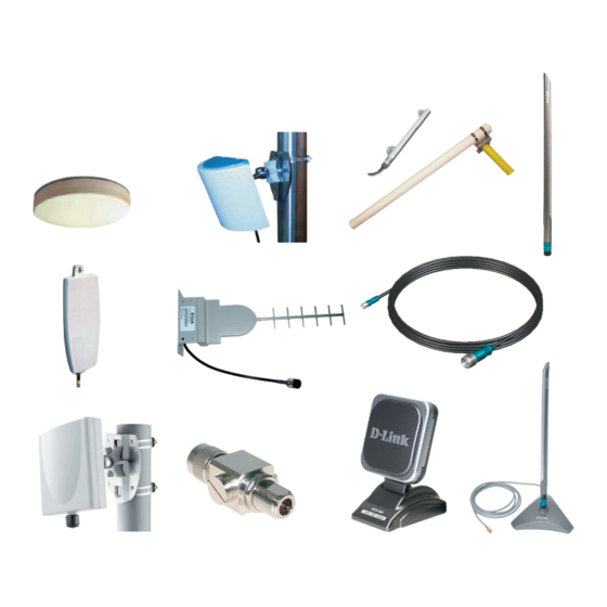
Antenna kits
Hide thumbs
Also See for ANT70-1800 - Dualband 2.4GHz & 5GHz Indoor/Outdoor Antenna:
- User manual (34 pages) ,
- User manual (34 pages) ,
- User manual (34 pages)

Related Manuals for D-Link ANT70-1800 - Dualband 2.4GHz & 5GHz Indoor/Outdoor Antenna


Summary of Contents for D-Link ANT70-1800 - Dualband 2.4GHz & 5GHz Indoor/Outdoor Antenna
- Page 1 DWL-AG700AP Install Guide User’s Guide Version 2.02 ANT24-Series ANT70-Series D-Link Antenna Kits...
- Page 2 System Requirements System Requirements ANT24-0700 Install Guide ANT24-0700 Install Guide Installation Note: /antenna (If needed) Install the surge protector. (You can install with optional ANT24 series low loss cables)
- Page 3 System Requirements System Requirements Installation ANT24-SP Surge protector Installation guide for outdoor antenna-kit Step 1 loosen the screw from the surge protector. Option (1) Option (2) Step 2 get a normal conductive copper wire with 2 sides stripped long enough to be conductive, these wires can lead high voltage surges into the grounding.
-
Page 4: Cable Loss
“ “Outdoor Installations Although D-Link offers a range of quality outdoor antennas, please note these devices are designed only to be installed by a professional as there are EU regulations that need to be considered. Cable lengths and quality will affect the antenna gain dramatically.”... - Page 5 System Requirements System Requirements ANT24-Series Electrical specifi cation 58°~75° 110g without joint Environmental & Mechanical Characteristics Temperature -10°C to 55°C Humidity 100% @ 25 C Lightning protection DC ground Radome color white Radome material Weight 100gw Dimensions 132 x 42 mm...
- Page 6 System Requirements System Requirements ANT24-0700 Install Guide ANT24-0700 Install Guide ANT24-Series Omni-Directional Antenna Version 1 Electrical specifi cation for 2.4 GHz SAA04-050170 Electrical Specification Frequency range 2400 MHz - 2500 MHz Ø19×330mm Gain 5.0 dBi Environmental & Mechanical Characteristics VSWR 2.0 : 1 Max.
-
Page 7: Physical Properties
2400~2500MHz Impedance 50Ω Normal ANT24-0700 / ANT24-0700C VSWR 1.92 Max Return Loss -10 dB Maximum Far-field amplitude of D-link-7dBi-H1-1020.nsi Far-field amplitude of D-link-7dB Antenna Structure Helis antenna Peak Gain ( w/o cable loss) 5dBi Admitted Power Cable loss( 1.5m) 2.1dB@2.45GHz E-Plane 36 deg. - Page 8 System Requirements System Requirements ANT24-0700 Install Guide ANT24-0700 Install Guide ANT24-Series Electrical specifi cation Frequency Range 2400~2500MHz Impedance 50Ω Normal VSWR 1.92 Max Peak Gain 5dBi Admitted Power E-Plane 36 deg. H-Plane 360 deg. Physical Properties Connector Reverse SMA plug Antenna Material ABS, ABS+PC Operating Temp...
- Page 9 System Requirements System Requirements ANT24-Series Electrical specifi cation 5.0dBi Typical 2.0:1 Max. 360° 30 degree nominal 197 mm(length) 29.5gw 30° Far-field amplitude of C147-510017-A-V.nsi Far-field amplitude of C147-510017-A-V.nsi 2.4GHz 2.45GHz 2.5GHz 2.4GHz 2.45GHz 2.5GHz Far-field amplitude of C147-510017-A-H.nsi Far-field amplitude of C147-510017-A-H.nsi 2.4GHz 2.45GHz 2.5GHz...
- Page 10 System Requirements System Requirements ANT24-0700 Install Guide ANT24-0700 Install Guide ANT24-Series Electrical specifi cation 6.0dBi Typical 2.0:1 Max. nominal 80x85x12.8 mm 75gw 85°...
- Page 11 System Requirements System Requirements ANT24-Series Electrical specifi cation Frequency Range 2400~2500MHz Impedance 50Ω Normal VSWR 1.92 Max Return Loss -10 dB Maximum Antenna Structure Pateh antenna Peak Gain ( w/o cable loss) 6.0 dBi @ 2.45GHz ( typical) Admitted Power Cable loss( 1.5m) 2.1dB@2.45GHz E-Plane...
- Page 12 Operating Temp -20°C ~ +65°C Storage Temp -30°C ~ +75°C Color Antenna: Metallic gray and silver Base: Metallic gray Package Contents -D-Link ANT24-0700 2.4GHz Omni-Directional Indoor Antenna -SMA to TNC Adapter -Magnetic Base with 1.5m Extension Cable -Mounting Kit -Installation Guide...
- Page 13 System Requirements System Requirements ANT24-Series Electrical specifi cation Frequency Range 2400~2500MHz Impedance 50Ω Normal VSWR 1.92 Max Return Loss 10 dB Maximum Antenna Structure Helis antenna Peak Gain ( w/o cable loss) 7dBi Admitted Power Cable loss( 1.5m) 2.1dB@2.45GHz E-Plane 24 deg.
- Page 14 Omni-Directional Antenna for 2.4 GHz System Requirements System Requirements ANT24-0700 Install Guide ANT24-0700 Install Guide ANT24-Series ANT24-0800A2 Electrical specifi cation Electrical Specification Frequency range 2400 MHz - 2500 MHz Gain 8.0 dBi VSWR 2.0 : 1 Max. Polarization Linear, vertical HPBW / horizontal Ø19×520mm 340g without joint...
- Page 15 System Requirements System Requirements ANT24-Series Electrical specifi cation Frequency 2400~2500MHz Gain 8.5 dBi VSWR 1.5 : 1 Max Polarization Linear, vertical HPBW / horizontal HPBW / vertical Front to back ratio 15 dB Power handling 50 W (cm) Impedance 50 Ohms Connector N - female Environmental &...
- Page 16 System Requirements System Requirements ANT24-0700 Install Guide ANT24-0700 Install Guide ANT24-Series Electrical specifi cation Frequency range 2400 MHz - 2500 MHz Gain 12 dBi VSWR 1.5 : 1 Max Polarization Linear, vertical HPBW / horizontal HPBW / vertical Front to back ratio 15 dB Downtilt Power handling...
- Page 17 System Requirements System Requirements ANT24-Series Electrical specifi cation Frequency range 2400 MHz - 2500 MHz Gain 12 dBi VSWR 1.5 : 1 Max Polarization Linear, vertical HPBW / horizontal HPBW / vertical Front to back ratio 15 dB Downtilt Power handling 10 W (cm) Impedance 50 Ohms...
- Page 18 System Requirements System Requirements ANT24-0700 Install Guide ANT24-0700 Install Guide ANT24-Series Electrical specifi cation Frequency range 2400 MHz - 2500 MHz Gain 14 dBi VSWR 1.5 : 1 Max Polarization Linear, vertical HPBW / horizontal HPBW / vertical Front to back ratio 15 dB Downtilt Power handling...
- Page 19 System Requirements System Requirements ANT24-Series Pole mounting method 1. Pole mounting method 2.
-
Page 20: Mechanical Properties
System Requirements System Requirements ANT24-0700 Install Guide ANT24-0700 Install Guide ANT24-Series Electrical specifi cation Frequency Range 2400~2500 MHz Impedance 50 OHMS ±5Ω 1=1.3 Max Gain 15 dBi Radiation Omni directional Polarization Vertical Mechanical Properties Connector N ( FEMALE) Weight 1050 g Radiator Copper Radome... - Page 21 System Requirements System Requirements ANT24-Series Electrical specifi cation Frequency range 2400 MHz - 2500 MHz Gain 18 dBi VSWR 1.5 : 1 Max Polarization Linear, vertical HPBW / horizontal HPBW / vertical Front to back ratio 26 dB Downtilt Power handling 50 W (cm) Impedance 50 Ohms...
- Page 22 System Requirements System Requirements ANT24-0700 Install Guide ANT24-0700 Install Guide ANT24-Series Electrical specifi cation Frequency range 2400 MHz - 2700 MHz Gain 18 dBi VSWR 1.5 : 1 Max Polarization Linear, vertical HPBW / horizontal HPBW / vertical Front to back ratio 25 dB Power handling 10 W (cm)
-
Page 23: Technical Data
System Requirements System Requirements ANT24-Series 2.4 GHz Antenna 2.4 GHz Antenna 1CO-24002 EVERTIME Communications Co., Ltd. 1CO-24002 EVERTIME Communications Co., Ltd. Return Loss Return Loss Electrical specifi cation Frequency Range 2400~2500 MHz Impedance 50 OHMS ±5Ω VSWR 1=1.5 Max Gain 21 dBi Radiation Directional... - Page 24 Please always install the antenna Picture (2) vertically to the horizontal surface, not recommended to mount it perpendicular to the wall. Package Contents 2.4 GHz: 5 GHz: -D-Link ANT70-0800 Antenna -Extension Cable(50cm) -Surge Protector -Mounting Kit Picture (3) -Water-proof tape Wall -Quick Installation Guide...
- Page 25 Please always install the antenna Picture (2) vertically to the horizontal surface, not 2.4 GHz: 5 GHz: recommended to mount it perpendicular to the wall. Package Contents -D-Link ANT70-0801 Antenna -Extension Cable(50cm) -Surge Protector -Mounting Kit -Water-proof tape Picture (3) -Quick Installation Guide Wall...
- Page 26 Radome material ABS, UV resistant Weight 150 g 5 GHz: Dimensions 114 x124 x 40 mm 2.4 GHz: 5 GHz: 2.4 GHz: 5 GHz: Package Contents -D-Link ANT70-1000 Antenna -Extension Cable(50cm) -Surge Protector -Mounting Kit -Water-proof tape -Quick Installation Guide...
- Page 27 ABS, UV resistant Assembly Drawing Weight 400 g ANT70-1800 Dimensions 200 x218 x 50 mm Assembly Drawing 2.4 GHz: 5 GHz: 2.4 GHz: 5 GHz: Package Contents -D-Link ANT70-1800 Antenna -Extension Cable(50cm) -Surge Protector -Mounting Kit -Water-proof tape -Quick Installation Guide...
-
Page 28: Line-Of-Sight (Los)
System Requirements System Requirements ANT24-0700 Install Guide ANT24-0700 Install Guide Fresnel Zone Line-of-Sight (LOS) Visual and RF Line-of-Sight ( LOS ) between the sending and receiving antennas is essential in achieving long range in wireless communication systems. There are two types of LOS that are generally used to describe an environment: Visual LOS is the ability to see from one site to the other. -
Page 29: Fresnel Zone
System Requirements System Requirements Fresnel Zone How far above the ground and other obstacles the antennas need to be is determined by the radius of the Fresnel zone. The radius of the Fresnal Zone depends upon the frequency and distance between the two radios. The following table provides approximate Fresnel zone radius: In order to have LOS clearance, the combined antenna height should be equal to or at least 70% of the radius of the Fresnel zone. -
Page 30: System Requirements
System Requirements ANT24-0700 Install Guide ANT24-Series... - Page 31 System Requirements...
- Page 32 System Requirements ANT24-0700 Install Guide...
- Page 33 System Requirements...
- Page 34 System Requirements ANT24-0700 Install Guide...
Need help?
Do you have a question about the ANT70-1800 - Dualband 2.4GHz & 5GHz Indoor/Outdoor Antenna and is the answer not in the manual?
Questions and answers