D-Link EasySmart DGS-1100-08P Manual
Easysmart series switch
Hide thumbs
Also See for EasySmart DGS-1100-08P:
- Manual (44 pages) ,
- Getting started manual (48 pages) ,
- User manual (55 pages)
Table of Contents
Advertisement
Advertisement
Table of Contents

Related Manuals for D-Link EasySmart DGS-1100-08P


Summary of Contents for D-Link EasySmart DGS-1100-08P
-
Page 2: Table Of Contents
Rear Panel ..............................5 Hardware Installation ..........................6 Step 1: Unpacking ............................6 Packing contents of DGS-1100-05/08 ......................6 Packing contents of DGS-1100-08P ......................6 Packing contents of DGS-1100-16/24 ......................6 Step 2: Switch Installation ..........................6 Desktop or Shelf Installation ........................6 Rack Installation ............................ - Page 3 Security > MAC Address Table > Static MAC ..................35 Security > MAC Address Table > Dynamic Forwarding Table ..............36 PoE > PoE Global Settings (DGS-1100-08P only) .................. 37 PoE > PoE Port Settings (DGS-1100-08P only) ..................38 Appendix A - Ethernet Technology ......................40 Gigabit Ethernet Technology ........................
- Page 4 D-Link Web Smart Switch User Manual L2 Features .............................. 41 VLAN ................................ 41 QoS (Quality of Service) ........................... 41 Management ............................. 41 Power Saving ............................41 Appendix C – Rack mount Instructions ..................... 42...
-
Page 5: About This Guide
Reproduction in any manner whatsoever without the written permission of D-Link Corporation is strictly forbidden. Trademarks used in this text: D-Link and the D-LINK logo are trademarks of D-Link Corporation; Microsoft and Windows are registered trademarks of Microsoft Corporation. Other trademarks and trade names may be used in this document to refer to either the entities claiming the marks and names or their products. -
Page 6: Product Introduction
Once if a packet is received, the switch wakes and works immediately. Connecting to EEE compliant devices, such as PCs and servers, the network can save energy without compromising any performance. While connecting to legacy devices which do not support IEEE 802.3az, D-Link Green Technologies can reduce power consumption by detecting short cable and link-down devices. -
Page 7: Front Panel
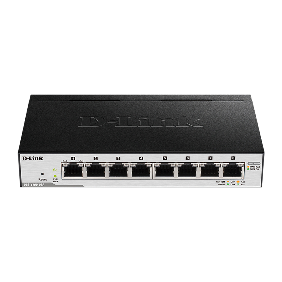
DGS-1100-08P 8-Port 10/100/1000Mpbs PoE EasySmart Switch Front Panel Figure 5 – DGS-1100-08P Front Panel Power LED: The Power LED lights up when the Switch is connected to a power source. PoE MAX. LED: Light up: Indicates the power output to PDs is over 57W. No additional PDs can be powered for safety consideration. -
Page 8: Rear Panel
Reset: By pressing the Reset button for 5 seconds the Switch will change back to the default configuration and all changes will be lost. Rear Panel Figure 6 – DGS-1100-08P Rear Panel 48V/1.57A Desktop adapter: The port is where to connect the 48V/1.57A Desktop adapter. DGS-1100-16... -
Page 9: Rear Panel
D-Link EasySmart Switch User Manual Rear Panel Figure 8– DGS-1100-16 Rear Panel Power: The power port is where to connect the AC power cord. DGS-1100-24 24-Port 10/100/1000Mpbs EasySmart Switch Front Panel Figure 9 – DGS-1100-24 Front Panel Power LED: The Power LED lights up when the Switch is connected to a power source. -
Page 10: Hardware Installation
D-Link EasySmart Switch User Manual Hardware Installation This chapter provides unpacking and installation information for the D-Link EasySmart Switch. Step 1: Unpacking Open the shipping carton and carefully unpack its contents. Please consult the packing list located in the User Manual to make sure all items are present and undamaged. If any item is missing or damaged, please contact your local D-Link reseller for replacement. -
Page 11: Rack Installation
D-Link EasySmart Switch User Manual Figure 11 – Attach the adhesive rubber pads to the bottom Rack Installation The switch can be mounted in an EIA standard size 11-inch rack, which can be placed in a wiring closet with other equipment. To install, attach the mounting brackets to the switch’s side panels (one on each side) and secure them with the screws provided (please note that these brackets are not designed for palm size switches). -
Page 12: Wall-Mount
D-Link EasySmart Switch User Manual B) Reduced Air Flow - Installation of the equipment in a rack should be such that the amount of air flow required for safe operation of the equipment is not compromised. C) Mechanical Loading - Mounting of the equipment in the rack should be such that a hazardous condition is not achieved due to uneven mechanical loading. -
Page 13: Power Failure
D-Link EasySmart Switch User Manual Figure 15 –Plugging the switch into an outlet Power Failure As a precaution, the switch should be unplugged in case of power failure. When power is resumed, plug the switch back in. Grounding the Switch This section describes how to connect the EasySmart Switch to ground. -
Page 14: Getting Started
This chapter introduces the management interface of D-Link EasySmart Switch. Management Options The D-Link EasySmart Switch can be managed through any port on the device by using the Web-based Management or through any PC using the SmartConsole Utility. Each switch must be assigned its own IP Address, which is used for communication with Web-Based Management. -
Page 15: Login Web-Based Management
Figure 19 – Logon Dialog Box SmartConsole Utility The SmartConsole Utility included in the installation CD is a program for discovering D-Link Smart Switches and EasySmart Switches within the same L2 network segment connected to your PC. This tool is only for computers running Windows 2000, Windows XP, Windows Vista x64/32 or Windows 7 x64/32 operating systems. - Page 16 Select SmartConsole Utility and double click on the .exe file. Follow the on-screen instructions to install the utility. Upon completion, go to Start > Programs > D-Link SmartConsole Utility and open the SmartConsole Utility. Connect the Smart Switch to the same L2 network segment of your PC and use the SmartConsole Utility to discover the Smart Switches.
-
Page 17: Smartconsole Utility
D-Link EasySmart Switch User Manual SmartConsole Utility The D-Link SmartConsole Utility allows the administrator to quickly discover all D-Link Smart Switches and EasySmart Switches which are in the same domain of the PC, collect traps and log messages, and quick access to basic configurations of the switch. -
Page 18: Log
D-Link EasySmart Switch User Manual NOTE: If the Group Interval is set to 0, IGMP Snooping must be disabled in the Switch or the switches will not be discovered. Click this icon to launch the Log window. Click View Log to show the events of the SmartConsole Utility and the device. -
Page 19: Monitor List
D-Link EasySmart Switch User Manual Monitor List By clicking on this icon you will see below options: Figure 24– SmartConsole Monitor List Monitor Save: Records the setting of the Device List as default for the next time the SmartConsole Utility is used. - Page 20 D-Link EasySmart Switch User Manual To apply the configuration, insert the correct device password in the Confirm Password box and then click Figure 26 – SmartConsole Device Settings NOTE: The EasySmart Switch automatically sends out discovery packets to maintain the...
-
Page 21: Add (+), Delete (-) And Discover The Device
D-Link EasySmart Switch User Manual Figure 28 –Firmware Upgrade DHCP Refresh: If a DHCP-client enabled switch in the Device List shows the default IP is still used, it means the device did not receive an IP address from the DHCP server successfully. Select that switch and click the DHCP refresh icon. -
Page 22: Device List
D-Link EasySmart Switch User Manual Figure 6– SmartConsole Delete device Device List This list displays all discovered Web Smart and EasySmart switches on the network. Figure 32– SmartConsole Device List Definitions of the Device List features: Monitor: The in the monitor means the device was discovered by SmartConsole. Click the icon to have the device keep updating the information, The icon will become . -
Page 23: Configuration
D-Link EasySmart Switch User Manual Configuration The features and functions of the D-Link EasySmart Switch can be configured for optimum use through the Web-based Management Utility. Web-based Management After a successful login you will see the screen below: Tool bar... -
Page 24: Tool Bar > Save Menu
D-Link EasySmart Switch User Manual Finally, by clicking on the D-Link logo at the upper-left corner of the screen you will be redirected to the local D-Link website. Tool Bar > Save Menu The Save Menu provides Save Configuration. Figure 34 – Save Menu Save Configuration Select to save the entire configuration changes you have made to the device to switch’s non-volatile RAM. -
Page 25: Configuration Backup & Restore
D-Link EasySmart Switch User Manual Click Browse to browse your inventories for a saved firmware file. Click Upgrade after selecting the firmware file you want to restore. Figure 89 – Tool Menu > Firmware backup & upgrade CAUTION: Do not disconnect the PC or remove the power cord from device until upgrade is complete. -
Page 26: Function Tree
D-Link EasySmart Switch User Manual Function Tree All configuration options on the switch are accessed through the Setup menu on the left side of the screen. Click on the setup item that you want to configure. The following sections provide more detailed description of each feature and function. -
Page 27: System > System Settings
D-Link EasySmart Switch User Manual Figure 92– Device Information System > System Settings The System Setting allows the user to configure the IP address and the basic system information of the Switch. IP Information: There are two ways for the switch to obtain an IP address: Static and DHCP (Dynamic Host Configuration Protocol). -
Page 28: System > Port Settings
D-Link EasySmart Switch User Manual System > Port Settings In the Port Setting page, the status of all ports can be monitored and adjusted for optimum configuration. By selecting a range of ports (From Port and To Port), the Speed can be set for all selected ports, effective by clicking Apply. -
Page 29: System > Password Access Control
D-Link EasySmart Switch User Manual Select the event message(s) to be sent out to the managing station. System Event: The system level messages contain: Device Bootup - System boot-up information Illegal Login - Events of incorrect password logins and records the IP of the source PC... -
Page 30: L2 Features > Igmp Snooping
D-Link EasySmart Switch User Manual Figure 158- L2 Features > Port Trunking Settings L2 Features > IGMP Snooping With Internet Group Management Protocol (IGMP) snooping, the EasySmart Switch can make intelligent multicast forwarding decisions by examining the contents of each frame’s Layer 2 MAC header. -
Page 31: L2 Features > Loopback Detection
D-Link EasySmart Switch User Manual TX (transmit) mode: Duplicates the data transmitted from the source port and forwards it to the Target Port. Click “all” to include all ports into port mirroring. RX (receive) mode: Duplicates the data that received from the source port and forwards it to the Target Port. -
Page 32: L2 Features > Cable Diagnostics
D-Link EasySmart Switch User Manual Figure 172– L2 Features > Statistics menu Refresh All: Renews the details collected and displayed. Clear All Counters: To reset the details displayed. TxOK: Number of packets transmitted successfully. RxOK: Number of packets received successfully. -
Page 33: Vlan > 802.1Q Vlan
D-Link EasySmart Switch User Manual NOTE: Cable length detection is effective at every speed of 10Mbps, 100Mbps and 1Gbps. VLAN > 802.1Q VLAN A VLAN is a group of ports that can be anywhere in the network, but communicate as though they were in the same area. -
Page 34: Vlan > 802.1Q Management Vlan
D-Link EasySmart Switch User Manual Figure 205– VLAN > 802.1Q VLAN > Add VID Figure 216– VLAN > 802.1Q VLAN > Assign PVID Rename: Click to rename the VLAN group. Delete VID: Click to delete the VLAN group. Figure 227– VLAN > 802.1Q VLAN > VLAN Table NOTE: When 802.1Q VLAN is enabled, the Port-... -
Page 35: Vlan > Port-Base Vlan
By default, all ports are untagged. VLAN > Surveillance VLAN Surveillance VLAN is a feature that allows you to automatically place the video traffic from D-Link IP cameras to an assigned VLAN to enhance the IP surveillance service. With a higher priority and individual VLAN, the quality and the security of surveillance traffic are guaranteed. - Page 36 2. Select a VLAN ID to become a surveillance VLAN and set the priority (By default, the priority is high) 3. D-Link Cameras can be recognized and placed into the VLAN dynamically. For other brands of camera or storages/servers, manual settings are required in “User-Defined MAC Settings” with a maximum entry number of 2: •Component Type: Surveillance VLAN will automatically detect D-Link Surveillance Devices by default.
-
Page 37: Vlan > Voice Vlan
VLAN > Voice VLAN Voice VLAN is a feature that allows you to automatically place the voice traffic from D-Link IP phones to an assigned VLAN to enhance the IP voice service. With a higher priority and individual VLAN, the quality and the security of voice traffic are guaranteed. -
Page 38: Qos > 802.1P Default Priority
D-Link EasySmart Switch system’s weight of priority levels are: 8 (Highest), 4 (High), 2 (Medium) and 1 (Low) packet. By default, the queuing mechanism is Strict Priority. -
Page 39: Qos > Bandwidth Control
D-Link EasySmart Switch User Manual Click Apply for the settings to take effect. QoS > Bandwidth Control The Bandwidth Control page allows network managers to define the bandwidth settings for a specified port’s transmitting and receiving data rates. Figure 296– QoS > Bandwidth Control From Port / To Port: A consecutive group of ports may be configured starting with the selected port. -
Page 40: Security > Mac Address Table > Dynamic Forwarding Table
D-Link EasySmart Switch User Manual Figure 307 – Security > Static Mac Address NOTE: DGS-1100-16/24 support 128 Static MAC Address entries, DGS-1100-05/08/08P only support 32 entries. To initiate the removal of auto-learning for any of the uplink ports, click On to enable this feature, and then select the port(s) for auto learning to be disabled. -
Page 41: Poe > Poe Global Settings (Dgs-1100-08P Only)
D-Link EasySmart Switch User Manual Figure 318 – Security >Dynamic Forwarding Table PoE > PoE Global Settings (DGS-1100-08P only) This page allows user to configure the global PoE settings of the device and also displays current PoE status including Total PoE Power Budget, Power Used, Power Left and The percentage of system power supplied. -
Page 42: Poe > Poe Port Settings (Dgs-1100-08P Only)
802.3af capable D-Link AP, IP Cam and IP phone equipment via the PoE splitter DWL-P50. DGS-1100-08P reserves 7 Watts for guard band in order to ensure the connection of the lowest priority PD. The maximum power used by power devices is defined by the following classification... - Page 43 D-Link EasySmart Switch User Manual Click Apply to make the configurations take effects or click Refresh to redisplay the table. NOTE: For the PoE Port Settings table, if the classification was shown as “Legacy PD”, it will be classified to non-AF PD or Legacy PD.
-
Page 44: Appendix A - Ethernet Technology
D-Link EasySmart Switch User Manual Appendix A - Ethernet Technology This chapter will describe the features of the D-Link EasySmart Switch and provide some background information about Ethernet/Fast Ethernet/Gigabit Ethernet switching technology. Gigabit Ethernet Technology Gigabit Ethernet is an extension of IEEE 802.3 Ethernet utilizing the same packet structure, format, and support for CSMA/CD protocol, full duplex, and management objects, but with a tenfold increase in theoretical throughput of over 100-Mbps Fast Ethernet and a hundredfold increase over 10-Mbps Ethernet. -
Page 45: Appendix B - Technical Specifications
D-Link EasySmart Switch User Manual Appendix B - Technical Specifications Hardware Specifications Emission (EMI) Certifications Key Components / Performance FCC class A Switching Capacity: CE Class A - DGS-1100-05 :10Gbps VCCI Class A - DGS-1100-08/08P: 16Gbps BSMI Class A(DGS-1100-08P only) -
Page 46: Appendix C – Rack Mount Instructions
D-Link EasySmart Switch User Manual Appendix C – Rack mount Instructions Safety Instructions - Rack Mount Instructions - The following or similar rack-mount instructions are included with the installation instructions: A) Elevated Operating Ambient - If installed in a closed or multi-unit rack assembly, the operating ambient temperature of the rack environment may be greater than room ambient.