Kyocera TASKalfa 4820w Hardware Operation Manual
Taskalfa 4820w operation guide
Hide thumbs
Also See for TASKalfa 4820w:
- Service manual (783 pages) ,
- Quick manual (24 pages) ,
- Safety manual (2 pages)
Table of Contents
Advertisement
Advertisement
Chapters
Table of Contents

Related Manuals for Kyocera TASKalfa 4820w


Summary of Contents for Kyocera TASKalfa 4820w
- Page 1 4820 / 9148 / 8148 Hardware Operation Guide...
- Page 2 Thank you for purchasing the Multi-Function Printer this machine. This Hardware Operation Guide contains functional and operational explanations for this machine. Please read this Hardware Operation Guide carefully before using the printer. Please keep this Hardware Operation Guide for future reference. 1.
-
Page 3: Safety Warnings
Safety Warnings The following warnings are very important in order to safely use this product. These notes are important in preventing danger to the operator or operation of the printer. The following symbols are found throughout the USER’S Manual and have the following meaning: WARNING This WARNING mark means that there is a possibility of death or serious injury if you ignore or do not follow the said instruction. - Page 4 WARNING Ground the product with a correct ground source or you may be electrically shocked. 1. The Power source should be as follows: 120 V Specification Model: 120V plus/minus10%, 50/60Hz, 15A or higher 230 V Specification Model: 220-240V plus6% or minus10%, 50/60Hz, 10A or higher 2.
- Page 5 CAUTION Do not install the printer in a humidified room or a dusty room. Also, do not install the printer on an unstable floor as injuries may occur. 1. Unplug the printer before you move it. The power cord may be damaged and it may result in a fire or electric shock.
-
Page 6: Table Of Contents
Chapter 1 Before Use page 1. 1 Installation Requirements 1- 2 1. 2 Originals Prohibited from Duplication 1- 3 1. 3 Features 1- 4 1. 4 Specifications 1- 5 1. 4. 1 General 1- 5 1. 4. 2 Printer part 1- 6 1. -
Page 7: Installation Requirements
1. 1 Installation Requirements The following conditions are required for installation of the equipment. 1. POWER SOURCE should be rated as follows. 120 V Specification Model: 120V plus/minus 10%, 50/60Hz, 15A or higher 230 V Specification Model: 220-240V plus 6% or minus10%, 50/60Hz, 10A or higher 2. -
Page 8: Originals Prohibited From Duplication
1. 2 Originals Prohibited from Duplication It is not necessarily allowed to copy every kind of original. You may be punished by the law if only you possess the copy of some kind of original. We recommend you to consider enough before you copy such original. [Originals prohibited from copying by the law] 1. -
Page 9: Features
1. 3 Features (1) This machine is a single footprint Multi-Function Printer which can copy, scan and print. Advanced drivers and comprehensive print utilities make this machine an advanced, easy to use system. (some functions may be optional) (2) HDP technology generates no waste toner. (3) The combination of the HDP Plus imaging system with mono-component minute toner produces high definition lines, distinctive greyscale and consistent blacks. -
Page 10: Specifications
1. 4 Specifications 1. 4. 1 General Subject Specification Model 4820/9148/8148 Configuration Console Power consumption 1,440W (120 V Specification Model ) (Maximum) 1,680W (230 V Specification Model ) (scanner / controller included) Power consumption 30W or less (Low power mode) Acoustic noise Idling Max. -
Page 11: Printer Part
1. 4. 2 Printer part Subject Specification Printing method LED Array Electro photography Photoreceptor Organic Photoconductive Drum Print speed 80mm per second (Inch) 3.4ppm/E 5.8ppm/D Landscape (Metric) 3.3ppm/A0 5.6ppm/A1 Landscape Print head LED Array Resolution of print head 600dpi x 600dpi Print width Maximum 914mm / 36”... - Page 12 Subject Specification Media source 2 Roll Decks Manual Feeder (single cut sheet) Paper Tray (multiple cut sheet, option) Media (Recommended Media) US model: Bond 64g/m to 80g/m , US Bond (PB-20) Vellum US Vellum (XV-20) Film 4MIL (PF-4DDME) Europe/Asia model: Plain Paper 64g/m to 80g/m...
-
Page 13: Scanner Part
1. 4. 3 Scanner part Subject Specification Scanning method Contact Image Sensor (CIS) (5 pieces of A4 sized CIS) Light source LED (R/G/B) Setting of original Face up Starting point of scan Center Scan width Max: 914.4mm / 36” Min : 210mm Scan length Max:... -
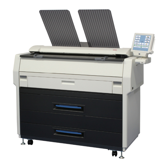
Page 14: Appearance
1. 5 Appearance 1. 5. 1 Front view 13 (OPTION) Name Function Main Switch You can turn on/off this machine. Original Guides Feed the original under the Scanner Unit along the Original Guides. User Interface This is a Touch Screen, and many kinds of user operation are available. -
Page 15: Rear View
1. 5. 2 Rear view Name Function Exit Cover Open the Exit Cover when you remove the paper misfed inside the Fuser Unit. LAN Port Connect the LAN Cable to connect this machine to the network. (Do not connect a telephone line) Dehumidify Heater Switch Turn on the Dehumidify Heater with this switch when you (Optional in the US) -
Page 16: Specifications For The Scan Original
1. 6 Specifications for the Scan Original A scan original must satisfy the following specifications. Thickness 0.05mm to 1.6mm Width 210mm to 914.4mm Length 210mm to 6,000mm (If an original is thicker than 0.65mm, its image quality may vary.) Do not scan the following kinds of originals. The original or the scanner may damage. Sticked with paste Paste Torn... - Page 17 Not square Metal or fabric material Metal Fabric Rough surface Rough surface (Carbon paper for example) Clipped or stapled Clipped Stapled 1-12 Chapter 1 Before Use...
- Page 18 The following kinds of originals can be read with using a carrier sheet. Image quality or the reliability of paper feeding for them is not guaranteed. Patched Punched 1-13 Chapter 1 Before Use...
-
Page 19: Specifications For The Printing Paper
1. 7 Specifications for the Printing Paper 1. 7. 1 Papers not available to use Do not use the following kinds of printing paper. Doing so may damage the print engine. Excessively curled (a diameter of 50 mm or less) Folded Creased Torn... -
Page 20: Keeping The Paper In The Custody
Pre-printed Extremely slippery Extremely sticky Extremely thin and soft OHP Film CAUTION Do not use the paper with staple, or do not use such conductive paper as aluminium foil and carbon paper. The above may result in a danger of fire NOTE (1) Print image may become light if printed on a rough surface of the paper. -
Page 21: Treatment Against Environmental Condition
1. 7. 3 Treatment against environmental condition Take a necessary treatment according to the environmental condition as shown below. Humidity(%) Possible problem Necessary treatment “Void of image”, “crease of paper” and 1. Install the humidifier in the room, and other problems occurs when you print humidify the room air. - Page 22 Chapter 2 Basic Operation page 2. 1 Turning on the Machine 2- 2 2. 2 Turning off the Machine 2- 4 2. 3 Replacing Roll Media 2- 5 2. 4 Replacing Toner Cartridge 2-11 2. 5 Cut Sheet Media 2-15 2.
-
Page 23: Turning On The Machine
2. 1 Turning on the Machine 1. Ensure that the machine is plugged into a dedicated wall outlet. WARNING (1) Do not handle the Power Plug with wet hands, or you may receive an electrical shock. (2) Make sure to earth the machine for safety. (3) Do not plug the printer into a multi-wiring connector in which other devices are plugged. - Page 24 3. The User Interface (UI) starts operating, and displays the following Copy Mode Screen in one minute. The Ready Indicator on Copy Mode Screen will flash during warming up. Ready Indicator The UI screen may vary depending on your system configuration. (Shown with available options) 4.
-
Page 25: Turning Off The Machine
2. 2 Turning off the Machine 1. There is a Power Switch on the right side of the machine. Press its “ ” side to turn off the machine. Power Switch Press “ ” side. CAUTION This machine print engine and UI appear to be shut down when you turn off the machine. However, the controller PC embedded inside this machine is still operating and will shutdown in approximately two minutes after Power Switch operation. -
Page 26: Replacing Roll Media
2. 3 Replacing Roll Media NOTE (1) A paper mis-feed tends to occur just before out of a roll paper. (2) A tracing roll paper is recommended to be loaded to Roll Deck 1 (front). Reference This section describes how to install a roll media to Roll Deck 1. The same procedure is applied to Roll Deck 2, unless otherwise noted. - Page 27 3. Raise the green lever (4) on Flange (2). Remove both Flanges (4) from the roll core (3). 4. Move a right Slide Guide (5) to match your roll media’s width. The right and left Side Guides will automatically move together. 5: for Roll 2 Size markings Chapter 2 Basic Operation...
- Page 28 5. Insert each Flange (2) into both ends of the roll media core to be installed. NOTE (1) Fully insert Flange into the roll media core so that the inside rim of Flange evenly touches the side face of the roll media. Inside Rim Inside Rim Correct: Fully inserted...
- Page 29 7. Lift the roll media by holding both Flanges. Lower Flanges onto Slide Guides (5) in Roll Deck. NOTE (1) Be careful of the winding direction of the roll media. Rear: Deck back Rear: Deck back Front: to media path Front: to media path Correct: Edge comes from bottom Wrong: Edge comes from top...
- Page 30 8. Insert the leading edge of the roll media under Guide Plate (8) until it touches the feeding roller. Rotate Feed Knob (9) clockwise so that the feeding rollers catch the leading edge. NOTE Use the rear Feed Knob (10) for Roll Deck 2. 9.
- Page 31 10. Slide the green Cutter Knob (12) fully from one side to the other to make a new straight edge. Remove the cut portion. NOTE Completely slide Cutter Knob (12) until it stops at either end. Not doing so may cause a paper jam. Correct Wrong 11.
-
Page 32: Replacing Toner Cartridge
2. 4 Replacing Toner Cartridge When the UI screen shows “Adding Toner”, follow the instruction to install a genuine Toner Cartridge. 1. Open the Toner Hatch (1). 2. Slide the green Lever (2) to the right to unlock the Toner Cartridge. (Lever (2) is held automatically.) NOTE Be sure to unlock the Toner Cartridge by releasing the green Lever (2). - Page 33 3. Pressing down the Cartridge Lock Lever (3), turn the body (4) of cartridge to the arrow direction until it stops. (You can close the toner supply hole of the cartridge firmly by this) NOTE The toner may drop from the toner supply hole, and it may scattered into the machine or on the floor if you remove the Toner Cartridge without closing the toner supply hole (5).
- Page 34 5. Shake the new Toner Cartridge left and right 5 times or more to make the toner smooth. After shaking, tilt the Toner Cartridge to the cap side. 6. Keep pressing down the Cartridge Lock Lever (3). Direct the toner supply hole to the floor, fit the pin (6) on the left side of the cartridge to the groove (7) on the machine side.
- Page 35 7. Turn the body (4) of the cartridge in one revolution to the arrow direction to open the toner supply hole. Confirm that the projection (8) if fitted into the notch (9). NOTE It is not necessary to lock the cartridge with the Lever (2).
-
Page 36: Cut Sheet Media
2. 5 Cut Sheet Media 1. Open the Bypass Feeder (1). Bypass Feeder 2. There are several size markings on the table of Bypass Feeder which indicate possible feed positions. Place the cut sheet paper on the table between its concerning size markings then insert it into the Bypass Feeder. -
Page 37: Copying
2. 6 Copying 1. There are several size markings on Original Table which indicate possible feed positions. Line up Original Guides with the proper markings according to the original width. Original Guide Original Guide 2. Place the original on the Original Table with face up. Then insert it under the Scanner Unit along with Original Guides. - Page 38 The machine has 2 print delivery system, the print tray (front, standard) / rear stacking equipment (back, option). NOTE For the front stacking, gently lift up the prints on the print tray to the arrow direction to avoid rubbing the print surface. A large number of prints should be removed in several sheets. Correct: Wrong: Gently lift up and remove...
-
Page 39: Emergency Stop Of Scan Or Copy
2. 7 Emergency Stop of Scan or Copy 1. If necessary, press the Emergency Stop Button (1) on the Scanner Unit to immediately stop the original while making a copy or scan. Pressing the button stops the current reading a document immediately. The current printing is stopped as well and is ejected. -
Page 40: Canceling Sleep Mode
2. 8 Canceling Sleep Mode This machine has two Sleep Modes to reduce the power consumption. This machine will enter Sleep Mode after a certain period of inactivity. In the default setting; Warm Sleep Mode will start after a 15 minute of inactivity in order to reduce the power supply for Fuser Unit. -
Page 41: Dehumidifying Roll Media
2. 9 Dehumidifying Roll Media If the roll paper is extremely humidified, it may cause several kinds of defective print. Defective prints you will experience most will be “crease of paper” and “loss of image”. Normal Print Crease of paper If the media is humidified;... - Page 42 Chapter 3 Error Correction page 3. 1 Mis-feed Error 3- 2 3. 1. 1 Deck Jam / Feeding Jam 3- 2 3. 1. 2 Manual Jam 3- 5 3. 1. 3 Reg. Jam / Internal Jam 3- 6 3. 1. 4 Fuser Jam 3- 7 3.
-
Page 43: Mis-Feed Error
3. 1 Mis-feed Error NOTE (1) Be careful not to get paper cuts on your hand. (2) It is recommended to take off your ring, bracelet or watch when removing a mis-feed media. (3) Gently remove a jammed paper. When it does not reach Fuser Unit, toner on it may spill off. - Page 44 3. Insert the leading edge of the roll media under Guide Plate (2) until it touches the feeding roller. Rotate Feed Knob (3) clockwise so that the feeding rollers catch the leading edge. NOTE (1) The leading edge should be trimmed with a cutter in case of an extreme crease.
- Page 45 5. Slide the green Cutter Knob (6) fully from one side to the other to make a new straight edge. Remove the cut portion. NOTE Completely slide Cutter Knob (6) until it stops at either end. Not doing so may cause a paper jam. Correct Wrong 6.
-
Page 46: Manual Jam
3. 1. 2 Manual Jam 1. Remove all Print Trays (1). 2. Pull up the Engine Unit Open Levers (2) to open the Engine Unit. 3. Remove the mis-fed paper pulling frontward. mis-fed media 4. Gently close the Engine Unit. NOTE (1) Be sure to close the Engine Unit firmly until it locks at the correct position. -
Page 47: Reg. Jam / Internal Jam
3. 1. 3 Reg. Jam / Internal Jam 1. Remove all Print Trays (1). 2. Pull up the Engine Unit Open Levers (2) to open the Engine Unit. 3. Remove the mis-fed paper. mis-fed media 4. Gently close the Engine Unit. NOTE Be sure to close the Engine Unit firmly until it locks at the correct position. -
Page 48: Fuser Jam
3. 1. 4 Fuser Jam 1. Remove all Print Trays (1). 2. Pull up the Engine Unit Open Levers (2) to open the Engine Unit. 3. Remove the mis-fed paper. If the mis-fed paper cannot be seen or removed, leave the media and go to the next step. If the paper (including any torn part) can be removed, go to step 8. - Page 49 5. Pull and remove the jammed print to the rear. If you remove the print at this time, just close the Exit Cover. If the print cannot be removed, go to the next step. If the print (including any torn part) can be removed, go to step 8.
- Page 50 7. Close Fuser Door (5) and Exit Cover (3). 8. Gently close the Engine Unit. NOTE Be sure to close the Engine Unit firmly until it locks at the correct position. 9. Replace Print Trays in the original position. Chapter 3 Error Correction...
-
Page 51: Stack Jam
3. 1. 5 Stack Jam 1. Remove print(s) on Print Trays. 2. Remove all Print Trays (1). 3. Pull up the Engine Unit Open Levers (2) to open the Engine Unit. 4. Pull and remove the jammed print to the top. If the print cannot be removed, see [3.1.4 Fuser Jam] for the later procedure of clearing the jammed print. -
Page 52: Original Jam
3. 1. 6 Original Jam 1. Open the Scanner Unit pulling up the Levers (1), and then remove the original. 2. Gently press Scanner Unit down and firmly close it. NOTE Press down Scanner Unit on both the sides to close it. Do not close it by pressing only one side down. -
Page 53: Other Operator Call Error
3. 2 Other Operator Call Error 3. 2. 1 Roll Replacement When the printer is running out of an loaded roll media, the UI Screen will display “Roll Replacement” sign. If there is no suitable roll media required for the current print job, the UI Screen will display “Roll Replacement”... -
Page 54: Service Call Errors
3. 3 Service Call Errors In case the following Error Codes for a serious failure appear in the UI screen; PLEASE CALL YOUR TRAINED SERVICE PERSONNEL TO RESOLVE THE ERRORS. No operation should be done by the customer. Error Code E - 000 E - 001 E - 002... - Page 55 Chapter 4 Maintenance page 4. 1 Cleaning 4- 2 4. 1. 1 Scanner Unit 4- 2 4. 1. 2 Touch Screen 4- 4 Chapter 4 Maintenance...
- Page 56 4. 1 Cleaning 4. 1. 1 Scanner Unit It is recommended to clean each Scan Glass, Feeding Rollers and Guide Plates as the scan/copy image may become defective if these parts are dirty. 1. Turn off the Machine. 2. Press the levers (1) up to unlock the Scanner Unit. Open the Scanner Unit. 3.
- Page 57 4. Wipe the Feed Rollers (4), Press Rollers (5) and the inside surface with a soft dry cloth. 5. Gently press Scanner Unit down and firmly close it. NOTE Press down Scanner Unit on both side to close it. Do not close it by pressing only one side down. Chapter 4 Maintenance...
- Page 58 4. 1. 2 Touch Screen 1. Wipe the Touch Screen with a dry cloth. NOTE Do not use water, alcohol, organic solvent and glass cleaner for the cleaning. Chapter 4 Maintenance...
- Page 59 Rev.1.0 2011.5 5JZKMEN001...
Need help?
Do you have a question about the TASKalfa 4820w and is the answer not in the manual?
Questions and answers