Table of Contents
Advertisement
GA-965P-DS3
Intel
Core
2 Extreme / Core
®
TM
Intel
Pentium
®
®
Intel
Pentium
®
®
User's Manual
Rev. 1002
12ME-965PDS3-1002R
* The WEEE marking on the product indicates this product must not be disposed of with user's other household waste
and must be handed over to a designated collection point for the recycling of waste electrical and electronic equipment!!
* The WEEE marking applies only in European Union's member states.
TM
Processor Extreme Edition
D / Pentium
4 LGA775 Processor Motherboard
®
2 Duo
Advertisement
Table of Contents

Related Manuals for Gigabyte GA-965P-DS3


Summary of Contents for Gigabyte GA-965P-DS3
- Page 1 GA-965P-DS3 Intel Core 2 Extreme / Core 2 Duo ® Intel Pentium Processor Extreme Edition ® ® Intel Pentium D / Pentium 4 LGA775 Processor Motherboard ® ® ® User's Manual Rev. 1002 12ME-965PDS3-1002R * The WEEE marking on the product indicates this product must not be disposed of with user's other household waste and must be handed over to a designated collection point for the recycling of waste electrical and electronic equipment!! * The WEEE marking applies only in European Union's member states.
- Page 3 Gigabyte's prior written permission. Specifications and features are subject to change without prior notice. Product Manual Classification In order to assist in the use of this product, Gigabyte has categorized the user manual in the following: For quick installation, please refer to the "Hardware Installation Guide" included with the product.
-
Page 4: Table Of Contents
Table of Contents Item Checklist ......................... 6 Optional Accessories ...................... 6 GA-965P-DS3 Motherboard Layout ................7 Block Diagram ........................ 8 Chapter 1 Hardware Installation ..................9 Considerations Prior to Installation ..............9 Feature Summary ..................10 Installation of the CPU and CPU Cooler ............12 1-3-1 Installation of the CPU .................. - Page 5 Xpress Recovery2 Introduction ................. 54 4-1-3 Flash BIOS Method Introduction ................ 56 4-1-4 Configuring SATA Hard Drive(s) (Controller: GIGABYTE SATA2) ....65 4-1-5 2- / 4- / 6- / 8- Channel Audio Function Introduction ........78 Troubleshooting ....................83 - 5 -...
-
Page 6: Item Checklist
Item Checklist IDE Cable x 1 and FDD Cable x 1 SATA 3Gb/s Cable x 4 I/O Shield * The items listed above are for reference only, and are subject to change without notice. Optional Accessories 2 Ports USB2.0 Cable (Part Number: 12CR1-1UB030-51/R) 4 Ports USB2.0 Cable (Part Number: 12CR1-1UB030-21/R) - 6 -... -
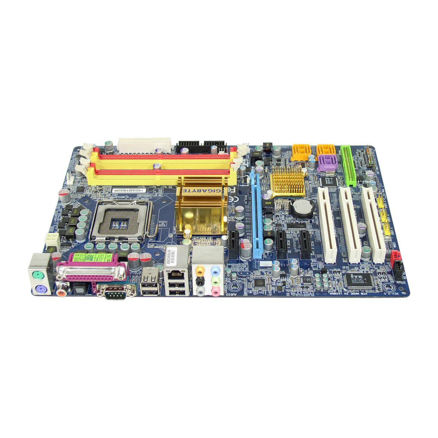
Page 7: Ga-965P-Ds3 Motherboard Layout
GA-965P-DS3 Motherboard Layout CPU_FAN ATX_12V KB_MS COAXIAL LGA775 OPTICAL Intel P965 ® AUDIO PCIE_3 M a r v e l l PCIE_16 88E8053 PCIE_1 CLR_CMOS PCIE_2 Intel ICH8 ® BATTERY SATAII0 CODEC PCI1 SATAII1 GSATAII0 GSATAII1 SATAII2 GIGABYTE PCI2 SATA2... -
Page 8: Block Diagram
DDRII 800/667/533MHz DIMM (Note) PCI Express x16 Dual Channel Memory Intel ® P965 MCHCLK (266/200/133MHz) 2 SATA 3Gb/s ATA33/66/100/133 RJ45 IDE Channel GIGABYTE Marvell SATA2 88E8053 PCI Express Bus BIOS 4 SATA 3Gb/s Intel ® PCI-E CLK ICH8 (100MHz) 3 PCI Express x1... -
Page 9: Chapter 1 Hardware Installation
2. Damage as a result of violating the conditions recommended in the user manual. 3. Damage due to improper installation. 4. Damage due to use of uncertified components. 5. Damage due to use exceeding the permitted parameters. 6. Product determined to be an unofficial Gigabyte product. - 9 - Hardware Installation... -
Page 10: Feature Summary
1 FDD connector, allowing connection of 1 FDD device 4 SATA 3Gb/s connectors (SATAII0,1, 2, 3), allowing connection of 4 SATA 3Gb/s devices Onboard GIGABYTE SATA2 chip 1 IDE connector (UDMA 33/ATA 66/ATA 100/ATA 133), allowing con- nection of 2 IDE devices... - Page 11 Rear Panel I/O 1 PS/2 keyboard port 1 PS/2 mouse port 1 SPDIF Out connection (coaxial+optical) 1 parallel port 4 USB 2.0/1.1 ports 1 serial port (COMA) 1 RJ-45 port 6 audio jacks (Line In / Line Out / MIC In/Surround Speaker Out (Rear Speaker Out)/Center/Subwoofer Speaker Out/Side Speaker Out) I/O Control IT8718 chip...
-
Page 12: Installation Of The Cpu And Cpu Cooler
(Grasping the CPU firmly between your thumb and forefinger, carefully place it into the socket in a straight and downwards motion. Avoid twisting or bending motions that might cause damage to the CPU during installation.) GA-965P-DS3 Motherboard - 12 -... -
Page 13: Installation Of The Cpu Cooler
1-3-2 Installation of the CPU Cooler Male Push Pin The top of Female Push Pin Female Push Pin Fig.1 Fig. 2 Please apply an even layer of heat paste on the (Turning the push pin along the direction of arrow is to surface of the installed CPU. -
Page 14: Installation Of Memory
DIMM socket. Then push it down. Fig.2 Close the plastic clip at both edges of the DIMM sockets to lock the DIMM module. Reverse the installation steps when you wish to remove the DIMM module. GA-965P-DS3 Motherboard - 14 -... - Page 15 The GA-965P-DS3 supports the Dual Channel Technology. After operating the Dual Channel Technology, the bandwidth of memory bus will double. The GA-965P-DS3 includes 4 DIMM sockets, and each Channel has two DIMM sockets as following: Channel 0 : DDRII1, DDRII2...
-
Page 16: Installation Of Expansion Cards
PCI Express x16 slot. When you try uninstall the VGA card, please gently press the latch as the picture to the left shows to release the card. GA-965P-DS3 Motherboard - 16 -... -
Page 17: I/O Back Panel Introduction
I/O Back Panel Introduction PS/2 Keyboard and PS/2 Mouse Connector To install a PS/2 port keyboard and mouse, plug the mouse to the upper port (green) and the keyboard to the lower port (purple). LPT (Parallel Port) The parallel port allows connection of a printer, scanner and other peripheral devices. COAXIAL (SPDIF Out) The SPDIF coaxial output port is capable of providing digital audio to external speakers or compressed AC3 data to an external Dolby Digital Decoder via a coaxial cable. -
Page 18: Connectors Introduction
) . Please refer to the 2-/4-/6-/8- channel audio setup steps for detailed software configuration information. Connectors Introduction ATX_12V F_PANEL ATX (Power Connector) F_AUDIO CPU_FAN CD_IN SYS_FAN SPDIF_I F_USB1 / F_USB2 / F_USB3 IDE1 SATAII0/1/2/3 CLR_CMOS GSATAII0/1 BATTERY PWR_LED GA-965P-DS3 Motherboard - 18 -... - Page 19 1/2) ATX_12V/ATX (Power Connector) With the use of the power connector, the power supply can supply enough stable power to all the components on the motherboard. Before connecting the power connector, please make sure that all components and devices are properly installed. Align the power connector with its proper location on the motherboard and connect tightly.
- Page 20 The FDD connector is used to connect the FDD cable while the other end of the cable connects to the FDD drive. The types of FDD drives supported are: 360KB, 720KB, 1.2MB, 1.44MB and 2.88MB. Before attaching the FDD cable, please take note of the foolproof groove in the FDD connector. GA-965P-DS3 Motherboard - 20 -...
- Page 21 6) IDE1 (IDE Connector) An IDE device connects to the computer via an IDE connector. One IDE connector can connect to one IDE cable, and the single IDE cable can then connect to two IDE devices (hard drive or optical drive).
- Page 22 8) GSATAII0/1 (SATA 3Gb/s Connector, Controlled by GIGABYTE SATA2) SATA 3Gb/s can provide up to 300MB/s transfer rate. Please refer to the BIOS setting for the Serial ATA and install the proper driver in order to work properly. Pin No.
- Page 23 10) F_PANEL (Front Panel Jumper) Please connect the power LED, PC speaker, reset switch and power switch etc. of your chassis front panel to the F_PANEL connector according to the pin assignment below. Speaker Connector Message LED/ Power Power/ Switch Sleep LED Reset Switch IDE Hard Disk Active LED...
-
Page 24: Front Audio Connector
FSENSE2 By default, the audio driver is configured to support HD Audio. To connect an AC97 front panel audio module to this connector, please refer to the instructions on Page 82 about the software settings. GA-965P-DS3 Motherboard - 24 -... - Page 25 12) CD_IN (CD IN) Connect CD-ROM or DVD-ROM audio out to the connector. Pin No. Definition CD-L CD-R 13) SPDIF_I (SPDIF In) Use SPDIF IN feature only when your device has digital output function. Be careful with the polarity of the SPDIF_I connector. Check the pin assignment carefully while you connect the SPDIF cable, incorrect connection between the cable and connector will make the device unable to work or even damage it.
- Page 26 No Pin 15) CI (Chassis Intrusion, Case Open) This 2-pin connector allows your system to detect if the chassis cover is removed. You can check the "Case Opened" status in BIOS Setup. Pin No. Definition Signal GA-965P-DS3 Motherboard - 26 -...
- Page 27 16) CLR_CMOS (Clear CMOS) You may clear the CMOS data to its default values by this header. To clear CMOS, temporarily short the two pins. Default doesn't include the jumper to avoid improper use of this header. Open: Normal Short: Clear CMOS 17) BATTERY Danger of explosion if battery is incorrectly replaced.
- Page 28 GA-965P-DS3 Motherboard - 28 -...
-
Page 29: Chapter 2 Bios Setup
CMOS SETUP screen. You can enter the BIOS setup screen by pressing "Ctrl + F1". If you wish to upgrade to a new BIOS, either Gigabyte's Q-Flash or @BIOS utility can be used. Q-Flash allows the user to quickly and easily update or backup BIOS without entering the operating system. -
Page 30: The Main Menu (For Example: Bios Ver. : F1B)
If you can't find the setting you want, please press "Ctrl+F1" to search the advanced option hidden. Please Load Optimized Defaults in the BIOS when somehow the system works not stable as usual. This action makes the system reset to the default for stability. GA-965P-DS3 Motherboard - 30 -... - Page 31 Standard CMOS Features This setup page includes all the items in standard compatible BIOS. Advanced BIOS Features This setup page includes all the items of Award special enhanced features. Integrated Peripherals This setup page includes all onboard peripherals. Power Management Setup This setup page includes all the items of Green function features.
-
Page 32: Standard Cmos Features
Auto Allows BIOS to automatically detect IDE/SATA devices during POST(default) None Select this if no IDE/SATA devices are used and the system will skip the automatic detection step and allow for faster system start up. GA-965P-DS3 Motherboard - 32 -... - Page 33 Access Mode Use this to set the access mode for the hard drive. The two options are: Large/Auto(default:Auto) Capacity Capacity of currently installed hard disk. Cylinder Number of cylinders Head Number of heads Precomp Write precomp Landing Zone Landing zone Sector Number of sectors Drive A...
-
Page 34: Advanced Bios Features
If you want to cancel the setting of password, please just press ENTER to make [SETUP] empty. (Note) This item will show up when you install a processor that supports this function. GA-965P-DS3 Motherboard - 34 -... - Page 35 CPU Hyper-Threading (Note) Enabled Enable CPU Hyper Threading Feature. Please note that this feature is only working for operating system with multi processors mode supported. (Default value) Disabled Disables CPU Hyper Threading. Limit CPUID Max. to 3 (Note) Enabled Limit CPUID Maximum value to 3 when use older OS like NT4. Disabled Disable CPUID Limit for windows XP.
-
Page 36: Integrated Peripherals
Disabled Disable this function. Azalia Codec Auto Auto detect Azalia audio function. (Default value) Disabled Disable Azalia audio function. Onboard H/W LAN Enabled Enable Onboard H/W LAN function. (Default value) Disabled Disable this function. GA-965P-DS3 Motherboard - 36 -... - Page 37 SMART LAN (LAN Cable Diagnostic Function) CMOS Setup Utility-Copyright (C) 1984-2006 Award Software SMART LAN Start detecting at Port..Item Help Pair1-2 Status = Normal / Length Menu Level Pair3-6 Status = Normal / Length Pair4-5 Status = Normal / Length Pair7-8 Status = Normal / Length...
- Page 38 This function decide whether to invoke the boot ROM of the onboard LAN chip. Enabled Enable this function. Disabled Disable this function. (Default value) Onboard SATA/IDE Device This function allows users to enable or disable the SATA/IDE ports controlled by the GIGABYTE SATA2 controller. Enabled Enable this function.(Default value) Disabled Disable this function.
-
Page 39: Power Management Setup
Power Management Setup CMOS Setup Utility-Copyright (C) 1984-2006 Award Software Power Management Setup ACPI Suspend Type [S1(POS)] Item Help Soft-Off by PWR-BTTN [Instant-Off] Menu Level PME Event Wake Up [Enabled] Power On by Ring [Enabled] Resume by Alarm [Disabled] x Date (of Month) Alarm Everyday x Time (hh:mm:ss) Alarm 0 : 0 : 0... -
Page 40: Pnp/Pci Configurations
Auto Auto assign IRQ to PCI 2. (Default value) 3,4,5,7,9,10,11,12,14,15 Set IRQ 3,4,5,7,9,10,11,12,14,15 to PCI 2. PCI3 IRQ Assignment Auto Auto assign IRQ to PCI 3. (Default value) 3,4,5,7,9,10,11,12,14,15 Set IRQ 3,4,5,7,9,10,11,12,14,15 to PCI 3. GA-965P-DS3 Motherboard - 40 -... -
Page 41: Pc Health Status
PC Health Status CMOS Setup Utility-Copyright (C) 1984-2006 Award Software PC Health Status Reset Case Open Status [Disabled] Item Help Case Opened Menu Level Vcore DDR18V +3.3V +12V Current System Temperature Current CPU Temperature Current CPU FAN Speed 3375 RPM Current SYSTEM FAN Speed CPU Warning Temperature [Disabled]... - Page 42 (Note) Before setting this item to Intel(R) QST, make sure at least DDRII1 or DDRII2 socket in Channel 0 is populated. A small portion of system memory will be shared when Intel QST is enabled. ® GA-965P-DS3 Motherboard - 42 -...
-
Page 43: Mb Intelligent Tweaker(M.i.t.)
MB Intelligent Tweaker(M.I.T.) CMOS Setup Utility-Copyright (C) 1984-2006 Award Software MB Intelligent Tweaker(M.I.T.) CPU Clock Ratio [16X] Item Help (Note) C.A.M (Note) [High] Menu Level CPU Host Clock Control [Disabled] x CPU Host Frequency (Mhz) PCI Express Frequency (Mhz) Auto C.I.A. - Page 44 Memory Frequency = Host clock X 3.33. 4.0+ Memory Frequency = Host clock X 4.0+. Auto Set Memory frequency by DRAM SPD data. (Default value) Memory Frequency (Mhz) The values depend on CPU Host Frequency (Mhz) and System Memory Multiplier setting. GA-965P-DS3 Motherboard - 44 -...
- Page 45 DIMM OverVoltage Control Please note that by overclocking your system through the increase of the DIMM voltage, damage to the memory may occur. Normal Set DIMM OverVoltage Control to Normal. (Default value) +0.1V Set DIMM OverVoltage Control to +0.1V. +0.2V Set DIMM OverVoltage Control to +0.2V.
-
Page 46: Load Fail-Safe Defaults
MB Intelligent Tweaker(M.I.T.) ESC: Quit : Select Item F8: Q-Flash F10: Save & Exit Setup Load Optimized Defaults Selecting this field loads the factory defaults for BIOS and Chipset Features which the system automatically detects. GA-965P-DS3 Motherboard - 46 -... -
Page 47: Set Supervisor/User Password
2-10 Set Supervisor/User Password CMOS Setup Utility-Copyright (C) 1984-2006 Award Software Standard CMOS Features Load Fail-Safe Defaults Advanced BIOS Features Load Optimized Defaults Integrated Peripherals Set Supervisor Password Power Management Setup Set User Password PnP/PCI Configurations Save & Exit Setup Enter Password: PC Health Status Exit Without Saving... -
Page 48: Save & Exit Setup
MB Intelligent Tweaker(M.I.T.) ESC: Quit : Select Item F8: Q-Flash F10: Save & Exit Setup Abandon all Data Type "Y" will quit the Setup Utility without saving to RTC CMOS. Type "N" will return to Setup Utility. GA-965P-DS3 Motherboard - 48 -... -
Page 49: Chapter 3 Install Drivers
Chapter 3 Install Drivers Pictures below are shown in Windows XP. Insert the driver CD-title that came with your motherboard into your CD-ROM drive, the driver CD-title will auto start and show the installation guide. If not, please double click the CD-ROM device icon in "My computer", and execute the Run.exe. -
Page 50: Software Applications
Software Applications This page displays all the tools that Gigabyte developed and some free software, you can choose anyone you want and press "install" to install them. Driver CD Information This page lists the contents of software and drivers in this CD-title. -
Page 51: Hardware Information
Hardware Information This page lists all device you have for this motherboard. Contact Us Please see the last page for details. - 51 - Install Drivers... - Page 52 GA-965P-DS3 Motherboard - 52 -...
-
Page 53: Chapter 4 Appendix
Toggles between Easy and Advance Mode Display screen Display panel of CPU frequency Function display LEDs Shows the current functions status GIGABYTE Logo Log on to GIGABYTE website Help button Display EasyTune 5 Help file Exit or Minimize button Quit or Minimize EasyTune... -
Page 54: Xpress Recovery2 Introduction
2. System storage capacity and the reading/writing speed of the hard disk will affect the data backup speed. 3. It is recommended that Xpress Recovery2 be immediately installed once you com- plete installations of OS and all required drivers as well as software. GA-965P-DS3 Motherboard - 54 -... - Page 55 The Main Screen of Xpress Recovery2 1. RESTORE: Restore the backed-up data to your hard disk. (This button will not appear if there is no backup file.) 2. BACKUP: Back up data from hard disk. 3. REMOVE: Remove previously-created backup files to release disk space.
-
Page 56: Flash Bios Method Introduction
Updating BIOS with Q-Flash Utility on Dual BIOS Motherboards. Some of Gigabyte motherboards are equipped with dual BIOS. In the BIOS menu of the motherboards supporting Q-Flash and Dual BIOS, the Q-Flash utility and Dual BIOS utility are combined in the same screen. - Page 57 Entering the Q-Flash utility: Step1: To use Q-Flash utility, you must press Del in the boot screen to enter BIOS menu. CMOS Setup Utility-Copyright (C) 1984-2004 Award Software Standard CMOS Features Select Language Advanced BIOS Features Load Fail-Safe Defaults Integrated Peripherals Load Optimized Defaults Power Management Setup Set Supervisor Password...
- Page 58 Save Main BIOS to Floppy Save Backup BIOS to Floppy Enter : Run :Move ESC:Reset F10:Power Off After BIOS file is read, you'll see a confirmation dialog box asking you "Are you sure to update BIOS?" GA-965P-DS3 Motherboard - 58 -...
- Page 59 3. Press Y button on your keyboard after you are sure to update BIOS. Then it will begin to update BIOS. The progress of updating BIOS will be displayed. Please do not take out the floppy disk when it begins flashing BIOS. 4.
-
Page 60: Updating Bios With Q-Flash Utility On Single-Bios Motherboards
PnP/PCI Configurations Set User Password PC Health Status Save & Exit Setup MB Intelligent Tweaker(M.I.T.) Exit Without Saving ESC: Quit F3: Change Language F8: Q-Flash F10: Save & Exit Setup Time, Date, Hard Disk Type... GA-965P-DS3 Motherboard - 60 -... - Page 61 Exploring the Q-Flash utility screen The Q-FlashBIOS utility screen consists of the following key components. Q-Flash utility bar Q-Flash Utility V1.30 Flash Type/Size.........SST 49LF003A 256K Keep DMI Data Enable Task menu for Update BIOS from Floppy Q-Flash utility Save BIOS to Floppy Action bar Enter : Run :Move...
- Page 62 6. Press Del to enter BIOS menu after system reboots and "Load BIOS Optimized Defaults". See how to Load BIOS Optimized Defaults, please kindly refer to Step 6 to 7 in Part One. Congratulation!! You have updated BIOS successfully!! GA-965P-DS3 Motherboard - 62 -...
- Page 63 BIOS. Fig 1. Installing the @BIOS utility Fig 2. Installation Complete and Run @BIOS Click Start/ Programs/ Gigabyte/ BIOS/ @BIOS Select @BIOS item than click Install Fig 3. The @BIOS Utility Fig 4. Select the desired @BIOS server Click "Update New BIOS"...
- Page 64 III. In method I, if the BIOS file you need cannot be found in @BIOS server, please go onto Gigabyte's web site for downloading and updating it according to method II. IV. Please note that any interruption during updating will cause system unbooted.
-
Page 65: Configuring Sata Hard Drive(S) (Controller: Gigabyte Sata2)
SATA controller for the connector. For example, on the GA-965P-DS3 motherboard, the GSATAII0 and GSATAII1 connectors are supported by the GIGABYTE SATA2 controller. Then connect the power connector from your power supply to the hard drive. - Page 66 The BIOS Setup menus described in this section may not show the exact settings for your motherboard. The actual BIOS Setup menu options you will see shall depend on the motherboard you have and the BIOS version. GA-965P-DS3 Motherboard - 66 -...
- Page 67 Init Display First [PCI] : Move Enter: Select +/-/PU/PD: Value F10: Save ESC: Exit F1: General Help F5: Previous Values F6: Fail-Safe Defaults F7: Optimized Defaults Figure 2 Step 3: Save and exit BIOS Setup. GA-965P-DS3 Motherboard - 67 -...
- Page 68 Press <Ctrl-G> to enter RAID Setup Utility ... Figure 3 In the main screen of the GIGABYTE RAID BIOS utility (Figure 4), use the UP or DOWN ARROW key to highlight through choices. Highlight the item that you wish to execute and press ENTER.
- Page 69 [ RAID Disk Drive List ] Select RAID Level RAID 0 Data striped for performance RAID 1 Data mirrored for redundancy JBOD Data concatenated for huge temporarily disk required ]-Switch RAID Level [ENTER]-Next [ESC]-Abort Figure 6 GA-965P-DS3 Motherboard - 69 -...
- Page 70 3. Assign Array Disks: After RAID mode is selected, RAID BIOS automatically assigns the two hard disks installed as the RAID disks. 4. Set Block Size (only for RAID 0): Under the Block item, use the UP or DOWN ARROW key to select the block size (Figure 7), ranging from 4K to 128K.
- Page 71 Rebuild Mirror Drive Save And Exit Setup Exit Without Saving [ RAID Disk Drive List ] Model Name RAID Level Capacity Status Members(HDDx) RDD0: GRAID 0-Stripe 240 GB Normal TAB]-Switch Window ]-Select RAID [ENTER]-Action [ESC]-Exit Figure 10 GA-965P-DS3 Motherboard - 71 -...
- Page 72 To check more detailed information about the array, use the TAB key while in the Main Menu block to move the selection bar to the RAID Disk Drive List block. Select the array and press ENTER. A small window displaying the array information will appear in the center of the screen (Figure 11). GIGA-BYTE Technology Corp.
- Page 73 B. Delete Array: To delete the array, select Delete RAID Disk Drive in the main menu and press ENTER. The selection bar will move to the RAID Disk Drive List block. Press the SPACEBAR on the array to be deleted; a small triangle will appear to mark the selected array (Figure 13).
- Page 74 Select the controller driver by pressing the corresponding letter from the menu. For example, from the menu in Figure 16, press E to select (E) GIGABYTE SATA-RAID Driver. Your system will then automatically zip and transfer this driver file to the floppy disk. Press 0 to exit when finished.
- Page 75 (5) Installing SATA controller driver during OS installation (Required for AHCI and RAID Mode) Now that you have prepared the SATA driver disk and configured BIOS settings, you are ready to install Windows 2000/XP onto your SATA hard drive with the SATA driver. The following is an example of Windows XP installation.
- Page 76 Use the ARROW keys to select one of the items displayed depending on the operating system to be installed. For example, select GIGABYTE GBB36X Controller (Windows 2K/XP/2003) if you wish to install Windows XP (32-Bit). Then press ENTER.
- Page 77 After the SATA controller driver installation is completed, you can proceed with the Windows 2000/XP installation. WindowsXP Professional Setup Welcome to Setup. This port of the Setup program prepares Microsoft(R) Windows (R) XP to run on your computer. To set up Windows XP now, press ENTER. To repair a Windows XP installation using Recovery Console, press R.
-
Page 78: 4- / 6- / 8- Channel Audio Function Introduction
After installation of the audio driver, you should find an Audio Manager icon in your system tray (you can also find the icon in Control Panel). Double- click the icon to open the Audio Control Panel. GA-965P-DS3 Motherboard - 78 -... - Page 79 STEP 2: In the Audio Control Panel, click the Audio I/O tab. In the upper left list, click 2CH Speaker. STEP 3: After a speaker or headphone is plugged into the rear Line Out jack, a small window will pop up and ask you what type of equipment is connected.
- Page 80 Choose a device depending on the type of speaker connected (6-channel audio consists of Front Speaker Out (Line Out), Rear Speaker Out, and Center/Subwoofer Speaker Out) then click OK. The 6-channel audio setup is completed. GA-965P-DS3 Motherboard - 80 -...
- Page 81 8 Channel Audio Setup STEP 1 : After installation of the audio driver, you should find an Audio Manager icon in your system tray (you can also find the icon in Control Panel). Double- click the icon to open the Audio Control Panel. STEP 2: In the Audio Control Panel, click the Audio I/O tab.
- Page 82 AC97 Audio mode, go to the Audio Control Panel and click the Audio I/O tab. In the ANA- LOG area, click the Tool icon and then select the Disable front panel jack detection check box. This action completes the AC'97 Audio configuration. GA-965P-DS3 Motherboard - 82 -...
-
Page 83: Troubleshooting
Below is a collection of general asked questions. To check general asked questions based on a specific motherboard model, please log on to GIGABYTE's website. Question 1: I cannot see some options that were included in previous BIOS after updating BIOS. Why? Answer: Some advanced options are hidden in new BIOS version. - Page 84 GA-965P-DS3 Motherboard - 84 -...
- Page 85 - 85 - Appendix...
- Page 86 GA-965P-DS3 Motherboard - 86 -...
- Page 87 Contact Us Taiwan (Headquarters) China GIGA-BYTE TECHNOLOGY CO., LTD. NINGBO G.B.T. TECH. TRADING CO., LTD. Address: No.6, Bau Chiang Road, Hsin-Tien, WEB address : http://www.gigabyte.cn Taipei 231, Taiwan Shanghai TEL: +886-2-8912-4888 TEL: +86-21-63410999 FAX: +886-2-8912-4003 FAX: +86-21-63410100 Tech. and Non-Tech. Support (Sales/Marketing) : Beijing http://ggts.gigabyte.com.tw...
- Page 88 Germany Russia G.B.T. TECHNOLOGY TRADING GMBH Moscow Representative Office Of GIGA-BYTE Technology WEB address : http://www.gigabyte.de Co., Ltd. U.K. WEB address : http://www.gigabyte.ru G.B.T. TECH. CO., LTD. Latvia WEB address : http://www.giga-byte.co.uk GIGA-BYTE Latvia The Netherlands WEB address : http://www.gigabyte.com.lv GIGA-BYTE TECHNOLOGY B.V.
Need help?
Do you have a question about the GA-965P-DS3 and is the answer not in the manual?
Questions and answers