Table of Contents
Advertisement
Quick Links
Advertisement
Table of Contents

Related Manuals for SSD Drives 637f

Summary of Contents for SSD Drives 637f
- Page 1 Servo drive Product Manual 07-02-10-01-E-V0505.doc...
- Page 2 Product Manual Bus Interface DP for 635 / 637 / 637+ / 637f UL:07-05-05-02 Product Manual Bus Interface Interbus S for 635 / 637 / 637+ / 637f UL:07-05-07-02 Product Manual I/O Interface for 635 / 637 / 637+ / 637f...
- Page 3 Additional Supporting Documentation UL:07-09-04-02 Product Manual Suppression Aids EH UL:10-06-03 Product Manual Serial Transfer Protocol 635 / 637 / 637+ / 637f EASY- Serial UL: CD ® EASYRIDER Windows - Software UL:10-06-05 ® Product Manual Software BIAS UL: 12-01 Product Manual Accessories - Plugs...
-
Page 4: Table Of Contents
Dimensions for Compact Device and Plug-In Module..............21 1.4.2 EMC-Clip (optional) ........................22 Connector Assignments and Functions ..........23 General View of Connections for Compact Device 637f/ K D6R 02 – 10 ........23 2.1.1 637f/K D6R 02...10 Width 14 HP ....................23 2.1.2 637f/K D6R 16...30 Width 20 HP .................... - Page 5 Digital communication see: Chapter 13..................60 Commissioning..................61 Preparation ........................... 61 Commissioning in steps........................ 62 Diagnose und Fehlersuche..............65 7-segment display......................... 65 Reset of a regulator trouble ......................69 Trouble shooting ........................... 70 Block circuit diagram ................71 ________________________________________________________________________________________________________________________________________________________________________________________________________________________ 07-02-10-01-E-V0505.doc Product Manaul Type: 637f...
- Page 6 11.10 Thermal data..........................75 11.11 Mechanical data..........................75 Disposal....................76 Software....................77 ® 13.1 EASYRIDER Windows - Software ....................77 13.2 SSD Drives programming language BIAS..................78 Certificates ....................81 Index ......................86 Modification Record ................88 ________________________________________________________________________________________________________________________________________________________________________________________________________________________ Product Manual Type: 637f 07-02-10-01-E-V0505.doc...
-
Page 7: The Most Important Thing First
Depending on the kind of application, additional regulations e.g. UL, DIN are subject to be observed. If our products are operated in connection with components from other manufacturers, their operating instructions are also subject to be observed strictly. ________________________________________________________________________________________________________________________________________________________________________________________________________________________ 07-02-10-01-E-V0505.doc Product Manaul Type: 637f... -
Page 8: Safety Precation
Expert configuration and professional installation, as described by this document, are the best way to insure for the problem-free operation Caution ! of the SSD Drives servo drive! ________________________________________________________________________________________________________________________________________________________________________________________________________________________ Product Manual Type: 637f 07-02-10-01-E-V0505.doc... -
Page 9: Safety Precautions
With measurements at the servo drive it is absolutely necessary to observe the potential separation SSD Drives GmbH is not liable for damages which may occur when the instructions and/or the applicable regulations are not explicitly observed! Stop ! ________________________________________________________________________________________________________________________________________________________________________________________________________________________ 07-02-10-01-E-V0505.doc Product Manaul Type: 637f... -
Page 10: General Information
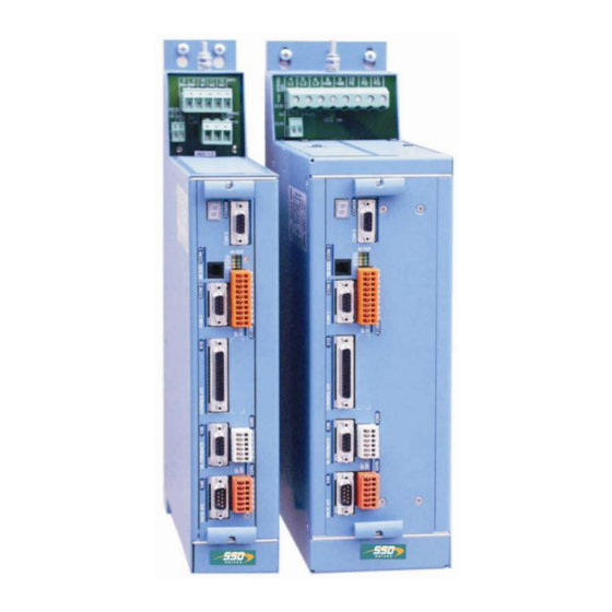
AC servo motors, (standard: with resolver) All control circuits and functions are realized digitally. System variants Rack - version: 637f/D6R..Compact - version: 637f/K D6R..Su pply volta ge: 637f/ K D6R Su pply volta ge: 637f/ K D6R 1* oder 3 *230 V AC/50..60 Hz... -
Page 11: Digital Communication
There are opportunities ranging from simple current and speed control to programmable position control processes (PLC), supported by the 1500 BIAS command blocks. "BIAS" User shell for intelligent drive controls see: chapter 3 Operating modes chapter 13.2 BIAS commands chapter 13.3 Extended BIAS commands ________________________________________________________________________________________________________________________________________________________________________________________________________________________ 07-02-10-01-E-V0505.doc Product Manaul Type: 637f... -
Page 12: Compatibility With 637 Servo Drives (Not Required For New Projects)
The 637f series servo drives are essentially pin- and functionally compatible with the servo drives 637. However, when a servo drive 637 is replaced with a 637f drive, the existing application must be checked and carefully tested to determine compliance under the corresponding safety precautions. - Page 13 -XXX -XXX -XXx -XXX type: 637f/ marking description 637f ≅ SSD Drives-fast-design XXXX/ 1-axis-compact digital-servo drive system design plug-in device Digital 6U drive Rated current: 2 amps 4 amps 6 amps 10 amps 16 amps 22 amps...
-
Page 14: Type Code
[C] Interface you can used 1 x CAN * Example: 637f/xD6Rxx.S5-x-x-232-EAE-RD2 … -232 = on slot A … -EAE = on slot C … -RD2 = on slot D (Motor - Feedbacksystem) ________________________________________________________________________________________________________________________________________________________________________________________________________________________ Product Manual Type: 637f 07-02-10-01-E-V0505.doc... -
Page 15: Layout Module Slots
JP102 1/ 3/ 2 JP100 2/ 3/ 1 JP1 1/ 3/ 2 JP2 2/ 3/ 1 JP3 1/ 3/ 2 JP4 2/ 3/ 1 JP209. 1/ 2/ 3 Solder jumper function see: Chapter 7.1 ________________________________________________________________________________________________________________________________________________________________________________________________________________________ 07-02-10-01-E-V0505.doc Product Manaul Type: 637f... -
Page 16: Range Data
Condition for Testing Frequency Range 10...57Hz 57...150Hz Amplitude 0,075 mm Acceleration Test Time per Axis 10 sweep cycle Frequency Sweep Speed 1 octave/min Use only fan-cooled devices. For reduced operating conditions, no UL approval is available. ________________________________________________________________________________________________________________________________________________________________________________________________________________________ Product Manual Type: 637f 07-02-10-01-E-V0505.doc... -
Page 17: Compact Units 637F/K D6R
General Information Range Data 1.3.3 Compact Units 637f/K D6R Compact Units 637f / K D6R 02 K D6R 04 K D6R 06 K D6R 10 K D6R 16 K D6R 22 K D6R 30 Input Supply Voltage min. 50..60 Hz... -
Page 18: Plug-In Modules 637F/D6R
General Information Range Data 1.3.4 Plug-In Modules 637f/D6R Plug-In Modules 637f/ D6R 02 D6R 04 D6R 06 D6R 10 D6R 16 D6R 22 D6R 30 Input DC-BUS Rated min. max. + 10% olerance Control Voltage 24V DC +20% -10%, attention: insulation-concept chapter 1.3.1 Control Current Continuous: max 0,8A Power-On-Peak: nom. -
Page 19: Single- And Three-Phase Supply
The unloaded output voltage will be reduced to approx. 90%, maximally 85 Single-phase supply: 50 – 60 Hz only servo drive 637f / ..02 up to 06 see the following diagram: Derating of servo drive output voltage in case of single-phase operationen... -
Page 20: Output Power
1.3.6 Output Power In case of continuous operation in the full-load range, the limits as shown in the following diagram need to be respected. Typical servo applications are not affected by this restriction. (S3 operation: Start/Stop). ________________________________________________________________________________________________________________________________________________________________________________________________________________________ Product Manual Type: 637f 07-02-10-01-E-V0505.doc... -
Page 21: Dimensions
71,0 mm 14,5 mm 14,5 mm 40,2 mm 8 HP 80,4 mm 16 HP Important Note: You will need additional space on the front side, of approx. 70 mm, for the signal mating plugs! ________________________________________________________________________________________________________________________________________________________________________________________________________________________ 07-02-10-01-E-V0505.doc Product Manaul Type: 637f... -
Page 22: Emc-Clip (Optional)
1.4.2.1 For 8 HP Drive side view front view 1.4.2.2 For 16 HP Drive side view front view EMC - Clip for Feedback cable (e.g. Resolver) Mains cable Motor cable Meaning: 1,2,3 = cage clamp terminals ________________________________________________________________________________________________________________________________________________________________________________________________________________________ Product Manual Type: 637f 07-02-10-01-E-V0505.doc... -
Page 23: Connector Assignments And Functions
Connector Assignments and Functions Connector Assignments and Functions General View of Connections for Compact Device 637f/ K D6R 02 – 10 2.1.1 637f/K D6R 02...10 Width 14 HP ________________________________________________________________________________________________________________________________________________________________________________________________________________________ 07-02-10-01-E-V0505.doc Product Manaul Type: 637f... -
Page 24: 637F/K D6R 16
Connector Assignments and Functions General View of Connections for Compact Device 637f/ K D6R 02 – 10 2.1.2 637f/K D6R 16...30 Width 20 HP ________________________________________________________________________________________________________________________________________________________________________________________________________________________ Product Manual Type: 637f 07-02-10-01-E-V0505.doc... -
Page 25: Connector Pin Assignments And Contact Functions
Connector Assignments and Functions Connector Pin Assignments and Contact Functions 2.2.1 Power Connections for Plug-In Module 637f/D6R (at the rear of the rack) (H15 multiple pin strip according to DIN 41612) ________________________________________________________________________________________________________________________________________________________________________________________________________________________ 07-02-10-01-E-V0505.doc Product Manaul Type: 637f... -
Page 26: Signal Connections
2.3.1 Control Signal Plug X10 - SUB D25 Socket Complete Representation X10 Reference to pin 22 & pin 23: With controllers with option module SBT, kindly note the extended functions of these signals (see documentation 07-02-10-02-E-Vxxxx). ________________________________________________________________________________________________________________________________________________________________________________________________________________________ Product Manual Type: 637f 07-02-10-01-E-V0505.doc... -
Page 27: Control Signal Plug X
1) Security- and supervising logic, to be programmed by user ! 2) IMPORTANT: The power-supply for the motor-brake has to be adapted to the type of brake. Voltage-Drops caused by long cables also may effect malfunctions of the brake. ________________________________________________________________________________________________________________________________________________________________________________________________________________________ 07-02-10-01-E-V0505.doc Product Manaul Type: 637f... - Page 28 Data of the digital inputs and outputs see chapter 11 General technical data Reference to Pin 22 & Pin 23: With controllers with option module SBT, kindly note the extended functions of these signals (see documentation 07-02-10-02-E-Vxxxx). ________________________________________________________________________________________________________________________________________________________________________________________________________________________ Product Manual Type: 637f 07-02-10-01-E-V0505.doc...
-
Page 29: Feedback Sensor X30
The connector X30 is directly related to the function module X300. This plug-in module (see chapter 1.4.3.1) determines the type of usable Feedback system. Thus the 637f drive system gets flexibility and is adaptable to future requirements. Types X300 Description... -
Page 30: Feedback Sensor Connection X30 (Sub D 09 Socket)
+ data - ref cos ref sin data + Sinus / Cosinus - Module X300_SC2 Module: X300_SC2 Function 5,5 V cos + sin + zero pulse + ref cos ref sin zero pulse - ________________________________________________________________________________________________________________________________________________________________________________________________________________________ Product Manual Type: 637f 07-02-10-01-E-V0505.doc... -
Page 31: Multi-Function X40
= 0,2V nominal signal difference: 1,0V current consumption: 1...4 mA (depending on frequency) Notice: Master / Slave operation 1 Master, maximum 8 Slaves Condition: Devices directly side by side ! ________________________________________________________________________________________________________________________________________________________________________________________________________________________ 07-02-10-01-E-V0505.doc Product Manaul Type: 637f... -
Page 32: Incremental Output
Parameter range of the input signals: 10...1000000 increments Figure: Note: The operation of incremental encoders via long cables may cause a voltage drop of the encoder power supply. We recommend the use of a separate voltage supply if necessary. ________________________________________________________________________________________________________________________________________________________________________________________________________________________ Product Manual Type: 637f 07-02-10-01-E-V0505.doc... -
Page 33: Stepper Motor Input
Supply voltage output max. 150 mA +5 VDC 2.5.4 Stepper Motor Input pulse positive / negative ® EASYRIDER Windows - Software X40 Mode = 3 Figure: Puls / Richtung Figure: Puls positiv / negativ ________________________________________________________________________________________________________________________________________________________________________________________________________________________ 07-02-10-01-E-V0505.doc Product Manaul Type: 637f... -
Page 34: Ssi Encoder Interface
DATA and /DATA twisted pair Cable screened, screen grounded at both sides, max. cable length: 200m Note: For further information about SSI (Synchronous Serial Interface), please refer to the documentations of appropriate suppliers. (e.g.: Comp. Sick or Hengstler) ________________________________________________________________________________________________________________________________________________________________________________________________________________________ Product Manual Type: 637f 07-02-10-01-E-V0505.doc... -
Page 35: Digital Interfaces
Transmit serial data do not connect Type Code Länge Beschreibung Kn PC 637f / 631-03.0 PC-side, Sub D 09-plug Kn PC 637f / 631-05.0 Drive side, 4-pin RJ 10-plug Note: The service interface RS232 is not galvanically isolated and should not be planned for this reason as an operating interface ("hard-wiring")! -
Page 36: Fieldbus Interface - Com2
The solder ring jumpers JP2.8, 2.3, 2.7, 2.2 must be switched dependent on the option module. See chapter 7.1 (factory-adjusted) 2.6.2.2 Additional CAN-BUS2 Interface (Use in combination with other Fieldbus) modul designation interface galvanic isolation design slot RP 2CA CAN2 RP 2C8 CAN2 additional plug COM 3 (B) ________________________________________________________________________________________________________________________________________________________________________________________________________________________ Product Manual Type: 637f 07-02-10-01-E-V0505.doc... - Page 37 RP 422, without galvanic isolation with option module RP 485, with galvanic isolation assignment as RS422/485 Data In Data In invertierted Data Out invertierted Data Out Parallel wiring up to 16 devices ________________________________________________________________________________________________________________________________________________________________________________________________________________________ 07-02-10-01-E-V0505.doc Product Manaul Type: 637f...
- Page 38 Request to send Ground Potential +5V Line A 2.6.2.8 Pin assignment for SUCOnet K with option module RP SUC, with galvanic isolation description designation Data line + TA/RA Signal ground SGND Data line - TB/RB ________________________________________________________________________________________________________________________________________________________________________________________________________________________ Product Manual Type: 637f 07-02-10-01-E-V0505.doc...
- Page 39 Data line OUT backward (error voltage A) Reference potential GND I Data line IN forward /DO1 (error voltage B) Data line OUT backward /DI1 (error voltage B) Attention: specific front panel is required ! ________________________________________________________________________________________________________________________________________________________________________________________________________________________ 07-02-10-01-E-V0505.doc Product Manaul Type: 637f...
- Page 40 The inputs with the internal number 107 and 108 must be connected to the pins with number 3 and 4. The outputs with the internal number 109 and 110 must be connected to the pins with number 7 and 8 ________________________________________________________________________________________________________________________________________________________________________________________________________________________ Product Manual Type: 637f 07-02-10-01-E-V0505.doc...
- Page 41 Bias output 221 standard output Bias output 222 standard output Bias output 223 standard Bias output 224 standard output +24 V SPS Ext. +24 V feed-in 0 V SPS Ground reference 0 V SPS ________________________________________________________________________________________________________________________________________________________________________________________________________________________ 07-02-10-01-E-V0505.doc Product Manaul Type: 637f...
- Page 42 Signal statuses of the I/O are indicated in each case by a 2mm LED at the front plate. Connector COM3 B – see chapter 2.6.2.6 LED lighten I/O = high LED off I/O = low X120 ________________________________________________________________________________________________________________________________________________________________________________________________________________________ Product Manual Type: 637f 07-02-10-01-E-V0505.doc...
- Page 43 I 0 0 250 kBaud I 0 I 500 kBaud I I 0 800 kBaud I I I 1000 kBaud (1MBaud) Example: node number 5; 1MBaud DIL – switch position bus termination COM2 COM3 Default COM2/COM3 ________________________________________________________________________________________________________________________________________________________________________________________________________________________ 07-02-10-01-E-V0505.doc Product Manaul Type: 637f...
-
Page 44: Option Module Rp Sbt
EN 292; EN 954 and EN 1050) the machine manufacturer must project the safety circuit of its machine types for the entire machine including all integrated components (also the electric drives). Block diagram: ________________________________________________________________________________________________________________________________________________________________________________________________________________________ Product Manual Type: 637f 07-02-10-01-E-V0505.doc... -
Page 45: Brake Control And Ptc Evaluation
I.e. also PTC thermistors (which correspond to the basis isolation) can be evaluated, without waiving the safe separation to the control electronics. Block diagram / Connector assignment Circuit diagram Further details see product manual 07-02-10-02-E-V.. ________________________________________________________________________________________________________________________________________________________________________________________________________________________ 07-02-10-01-E-V0505.doc Product Manaul Type: 637f... -
Page 46: Operating Modes
BIAS to programming or via (up to 1500 command blocks) digital communication PLC - functions (e.g. fieldbus) for further information: see chapter 13.1 and 13.2 ________________________________________________________________________________________________________________________________________________________________________________________________________________________ Product Manual Type: 637f 07-02-10-01-E-V0505.doc... -
Page 47: Operating Modes And Pin Functions
F0, F2, F5 F0, F2, F5 F0, F2, F5 F0, F1,F3, F5 F0, F1,F3, F0, F1, F2, F3, X10.23 F4, F5 The assignment of the functions F0..F5 is listed in the following table ________________________________________________________________________________________________________________________________________________________________________________________________________________________ 07-02-10-01-E-V0505.doc Product Manaul Type: 637f... -
Page 48: Configurable Pin-Functions (Depending On The Operating Mode)
RP-CAN. 3) Is the Option RP 2C8 (chapter. 2.6.2.12) insertion, are the contact function as the same definition on X10- plug invalid (the inputs can freely programmable and use in BIAS program) ________________________________________________________________________________________________________________________________________________________________________________________________________________________ Product Manual Type: 637f 07-02-10-01-E-V0505.doc... -
Page 49: Function Diagrams From Inputs And Outputs
AK TIVE -O K (F0) X 10.23 (holdin g br ake ) Hint: With the assembly of the option module SBT you kindly note the extended functions of the signals (see documentation 07-02-10-02-E..) ________________________________________________________________________________________________________________________________________________________________________________________________________________________ 07-02-10-01-E-V0505.doc Product Manaul Type: 637f... -
Page 50: Mechanical Installation
If the device becomes operated in a not ventilated device, the case volume of the specified control cabinet must be calculated in accordance with the following table ! Units Volume of cabinet 637f/0D6R02...D6R10 0,12 m³ 637f/0D6R16...D6R30 0,25 m³ For more exact information, please, address to the control-cabinet manufacture ________________________________________________________________________________________________________________________________________________________________________________________________________________________ Product Manual Type: 637f 07-02-10-01-E-V0505.doc... -
Page 51: Electrical Installation
Due to the working-principle of servo drives there may discharge currents to PE exceeding DC 10mA resp. AC 3,5mA. Suitable for use on a circuit capable of delivery not more than 5000 RMS symmetrical amperes 505V maximum. (Note according to UL508C) ________________________________________________________________________________________________________________________________________________________________________________________________________________________ 07-02-10-01-E-V0505.doc Product Manaul Type: 637f... -
Page 52: Fuses, Contactors, Filters
LNF B 3*480/018; LNF B 3*480/033 + ferrite core FR max motor cable 20m other types upon request (EN55011 B) (according to ref.measurements with 3 units, supplied by common line) Plug-in modules 637f / D6R 02 D6R 04 D6R 06 D6R 10 D6R 16 D6R 22... -
Page 53: Correction Of Supply Current
In other cases, the value has to be corrected using the following diagram. Example: Drive type 637f/KD6R16.S5-7 is supplied by AC 230V 3-ph. Output-power: Pout = 200V x 16A x 1,73 = 5,54 kW This output-power must be generated by:... -
Page 54: Brake Resistor
Pmax = (1,8 * Pkin) - Pvmot [W] used units: total inertia [kgm²] speed at Brake-Start [RPM] tb1 braking time [Sec] cykle time [Sec] brake-current [A] Rph resistance of motor (between terminals) [Ω] RL line resistance of motor cable [Ω] ________________________________________________________________________________________________________________________________________________________________________________________________________________________ Product Manual Type: 637f 07-02-10-01-E-V0505.doc... -
Page 55: Configuration Of The Brake Resistor
Possible ballast circuit configurations at digital devices Compact design The plug-in modules of servo-control series 635/637/637+/637f are provided with an on board ballast electronics. It is intended for application as compact unit KDER resp. KD6R. These compact units contain the necessary ballast resistor incl. fuse for the ballast circuit. - Page 56 Set up rated power = 130 Watt Caution ! Placing of external brake resistors Brake-resistor are dissipating heat ! Make sure, that there will be no fire-danger in case of operating the resistor in nominal- or fail-conditions ________________________________________________________________________________________________________________________________________________________________________________________________________________________ Product Manual Type: 637f 07-02-10-01-E-V0505.doc...
-
Page 57: Wiring Instructions
The measurements made are valid under the use of SSD Drives - cables, suppression aids and line filters and by application of the following wiring instructions: ________________________________________________________________________________________________________________________________________________________________________________________________________________________ 07-02-10-01-E-V0505.doc Product Manaul Type: 637f... -
Page 58: Hints For Mounting
Take care for good general grounding of the complete system. Interconnect several mounting-plates with copper-rails or copperband. Take care for ground connection between control-cubicle and machine ! ________________________________________________________________________________________________________________________________________________________________________________________________________________________ Product Manual Type: 637f 07-02-10-01-E-V0505.doc... -
Page 59: Example For Mounting
≥ 15 dB cores cable or by air attenuation Residential EN50081-1/ LNF S/E chapter EN55011 Klasse chapter 5.6 LNF B Interference Industrial EN50082-2 immunity: (≅ radiation) transmitted by cable or by air Residential ________________________________________________________________________________________________________________________________________________________________________________________________________________________ 07-02-10-01-E-V0505.doc Product Manaul Type: 637f... -
Page 60: Setting And Programming
RP 232, RP 422, RP 485, RP IBS, RP EA5, RP SUC JP209 2-3 JP209 1-3 close Default RP SBT Further connecting configuration see: Product Manualo 07-02-10-02-E-Vxxxx RP_SBT Digital communication see: Chapter 13 ________________________________________________________________________________________________________________________________________________________________________________________________________________________ Product Manual Type: 637f 07-02-10-01-E-V0505.doc... -
Page 61: Commissioning
To activate the power-stage of the drive, the "ACTIVE"-signal (X10.22 against X10.9) has to be exited. Hint: With the assembly of the option module SBT you kindly note the extended functions of the signals (see documentation 07-02-10-02-E..) ________________________________________________________________________________________________________________________________________________________________________________________________________________________ 07-02-10-01-E-V0505.doc Product Manaul Type: 637f... -
Page 62: Commissioning In Steps
Connect PC by RS232 link to the drive service port COM1 ® and start EASYRIDER 7-segment- Set up state dispay NOT ACTIVE 635/ 637/ 637+/ 637f X10.22 against X10.9 X10.7 against X10.4 Power on Switch on control voltage 7-segment- dispay... - Page 63 Further functions (Interfaces, fieldbus functions, synchronizing and so on may be done adapted to selected equipments Select the menu “File” store parameters” and store the data save data in the regulator, protect against lost, with F7-key ________________________________________________________________________________________________________________________________________________________________________________________________________________________ 07-02-10-01-E-V0505.doc Product Manaul Type: 637f...
- Page 64 Sometimes it is recommended to make further manual tuning. Rated value can be soured either digital by the internal generator or analogue by P- gain too high or I-time constant too 635/ 637/ 637+/ 637f small +/- 10V at X10.5/18 +/- 10V at X10.1/2 Motor noise...
-
Page 65: Diagnose Und Fehlersuche
With configuration corresponding chapter : Operating modes and pin functions Only warning respect. status indicator The error signals are shown as long as there is control voltage (Us), also when the power (DC-Bus) is switched off for safety reasons. ________________________________________________________________________________________________________________________________________________________________________________________________________________________ 07-02-10-01-E-V0505.doc Product Manaul Type: 637f... - Page 66 With configuration corresponding chapter : Operating modes and pin functions Only warning respect. status indicator The error signals are shown as long as there is control voltage (Us), also when the power (DC-Bus) is switched off for safety reasons. ________________________________________________________________________________________________________________________________________________________________________________________________________________________ Product Manual Type: 637f 07-02-10-01-E-V0505.doc...
- Page 67 With configuration corresponding chapter : Operating modes and pin functions Only warning respect. status indicator The error signals are shown as long as there is control voltage (Us), also when the power (DC-Bus) is switched off for safety reasons. ________________________________________________________________________________________________________________________________________________________________________________________________________________________ 07-02-10-01-E-V0505.doc Product Manaul Type: 637f...
- Page 68 With configuration corresponding chapter : Operating modes and pin functions Only warning respect. status indicator The error signals are shown as long as there is control voltage (Us), also when the power (DC-Bus) is switched off for safety reasons. ________________________________________________________________________________________________________________________________________________________________________________________________________________________ Product Manual Type: 637f 07-02-10-01-E-V0505.doc...
-
Page 69: Reset Of A Regulator Trouble
The error signal (releasing before ready) can be reset by deactivation the drive. Hint: With the assembly of the option module SBT you kindly note the extended functions of the signals (see documentation 07-02-10-02-E..) ________________________________________________________________________________________________________________________________________________________________________________________________________________________ 07-02-10-01-E-V0505.doc Product Manaul Type: 637f... -
Page 70: Trouble Shooting
Encoder incorrectly adjusted? (e.g. Resolver) Motor reaches in idling cycle very different Feedback-Encoder incorrectly adjusted speed when running to the right or to the left (e.g. Resolver) 1) Display mostly short after activating; before warning ________________________________________________________________________________________________________________________________________________________________________________________________________________________ Product Manual Type: 637f 07-02-10-01-E-V0505.doc... -
Page 71: Block Circuit Diagram
Block Circuit Diagram Block circuit diagram ________________________________________________________________________________________________________________________________________________________________________________________________________________________ 07-02-10-01-E-V0505.doc Product Manaul Type: 637f... -
Page 72: General Technical Data
(0-->24V): Interrupt response time for fast input 10µs (X10.4, X10.25) Damping of the transfer from fast input: Damping of the transfer high to low (24-->0V) from 250µs (X10.4, X10.25) high to low (24-->0V) ________________________________________________________________________________________________________________________________________________________________________________________________________________________ Product Manual Type: 637f 07-02-10-01-E-V0505.doc... -
Page 73: Signal Inputs And Outputs, Connection X120B Resp. 120C
U soll = 10 V, can be normed; R i = 10k resolution (including sign) 14 bit digital setpoint input via interfaces position control Loop-Cycle-Time 105 µs ________________________________________________________________________________________________________________________________________________________________________________________________________________________ 07-02-10-01-E-V0505.doc Product Manaul Type: 637f... -
Page 74: Digitale Communication
Data under check, Reality: Quality improved 11.8 Controllersystem system run-up time after switching on max. 6 sec. the control voltage data memory / organization Flash Eprom 256 KB RAM 64 KB; EEPROM 96 kByte ________________________________________________________________________________________________________________________________________________________________________________________________________________________ Product Manual Type: 637f 07-02-10-01-E-V0505.doc... -
Page 75: Analog-Outps
8 bit, independend of norming internal resistance 1,8 kOhm 11.10 Thermal data thermal data see chapter 1.3 11.11 Mechanical data dimensions see chapter 1.4 weight see chapter 1.3 Further data you will find in chapter 1.3 ________________________________________________________________________________________________________________________________________________________________________________________________________________________ 07-02-10-01-E-V0505.doc Product Manaul Type: 637f... -
Page 76: Disposal
The following table shows, which materials can be recycled and which have to be disposed of in a special way. material recycle disposal Metal plastics material printed board assembly Dispose of the appropriate materials in accordance with the valid environmental control laws. ________________________________________________________________________________________________________________________________________________________________________________________________________________________ Product Manual Type: 637f 07-02-10-01-E-V0505.doc... -
Page 77: Software
RAM of the servo drive and active after use of the instruction SEND. Only the instruction SAVE in EEPROM writes data into a not volatile memory. Data are stored there power-fail save. ________________________________________________________________________________________________________________________________________________________________________________________________________________________ 07-02-10-01-E-V0505.doc Product Manaul Type: 637f... -
Page 78: Ssd Drives Programming Language Bias
-Type-conversions long integer <=> double float (Math.task only) -Fundamental operations of arithmetic with double float (Math.task only) -SIN(x),COS(x),SQRT(x) with double float (Math.task only) -Writing and reading of synchronous profile tables. CAN-Bus commands -Communication with other SSD Drives products ________________________________________________________________________________________________________________________________________________________________________________________________________________________ Product Manual Type: 637f 07-02-10-01-E-V0505.doc... - Page 79 The BIAS operation set is listed on the next page. ® You can read the exact function of the individual commands in the help function of the EASYRIDER Windows -Software in the BIAS editor or in the BIAS command description (10-06-05-E-Vxxxx). ________________________________________________________________________________________________________________________________________________________________________________________________________________________ 07-02-10-01-E-V0505.doc Product Manaul Type: 637f...
-
Page 80: Bias Commands
Command group “Program control commands“ Command group “Parameter commands“ Command group “Mathematic commands“ Command group “Variable commands“ Command group “Output commands“ Command group “Flag commands“ Command group “CAN- Commands“ Command group “Conditional jump commands“ Command group “637f commands“ ________________________________________________________________________________________________________________________________________________________________________________________________________________________ Product Manual Type: 637f 07-02-10-01-E-V0505.doc... -
Page 81: Certificates
Certificates Certificates ________________________________________________________________________________________________________________________________________________________________________________________________________________________ 07-02-10-01-E-V0505.doc Product Manaul Type: 637f... - Page 82 Certificates ________________________________________________________________________________________________________________________________________________________________________________________________________________________ Product Manual Type: 637f 07-02-10-01-E-V0505.doc...
- Page 83 Certificates ________________________________________________________________________________________________________________________________________________________________________________________________________________________ 07-02-10-01-E-V0505.doc Product Manaul Type: 637f...
- Page 84 Certificates ________________________________________________________________________________________________________________________________________________________________________________________________________________________ Product Manual Type: 637f 07-02-10-01-E-V0505.doc...
- Page 85 Certificates ________________________________________________________________________________________________________________________________________________________________________________________________________________________ 07-02-10-01-E-V0505.doc Product Manaul Type: 637f...
-
Page 86: Index
Combination possibilities for the various communications / Grounding, safety grounding..........51 I/O - modules ..............14 Commissioning..............61 Commissioning in steps............62 Compact Units 637f/K D6R ..........17 Compatibility with 637+ Servo Drives......12 H15 multiple pin strip ............25 Compatibility with 637 Servo Drives.........12 Hints for mounting .............58 ®... - Page 87 System Description............10 Pin assignment for RS422/485 .......... 37 System variants ..............10 Pin assignment for SUCOnet K......... 38 Plug-In Modules 637f/D6R ..........18 Power cabling ..............57 Power circuit ..............72 Preparation ................ 61 The Most Important Thing First .......... 7 Thermal data..............
-
Page 88: Modification Record
7-segment display 9.1-9.2 new options new BIAS commands 13.3 16.03.04 N. Dreilich V03004 SSD Drives 19.10.2004 N.Dreilich Logos V0405 diverse correction (text, design and photos) 12.05.2005 N. Dreilich V0505 Model code, extended 18.05.2005 N. Dreilich ________________________________________________________________________________________________________________________________________________________________________________________________________________________ Product Manual Type: 637f 07-02-10-01-E-V0505.doc...
Need help?
Do you have a question about the 637f and is the answer not in the manual?
Questions and answers