
Related Manuals for Vaisala HUMICAP MM70

Summary of Contents for Vaisala HUMICAP MM70
- Page 1 USER'S GUIDE Vaisala HUMICAP® Hand-Held Moisture and Temperature in Oil Meter MM70 M210498EN-C...
- Page 2 The contents are subject to change without prior notice. Please observe that this manual does not create any legally binding obligations for Vaisala towards the customer or end user. All legally binding commitments and agreements are included exclusively in the applicable supply contract or Conditions of...
-
Page 3: Table Of Contents
Trademarks ................6 License Agreement ..............6 Warranty..................7 CHAPTER 2 PRODUCT OVERVIEW AND MECHANICS ..........9 Vaisala´s Hand-held MM70 Device ......... 9 Structure of the MI70 Indicator..........10 Structure of the MMP78 Probe..........11 Tools..................11 Display Parameters ..............12 Options .................. - Page 4 USER'S GUIDE____________________________________________________________________ Rounding ................24 Hold/Save Display ...............25 Graphic History..............25 User Interface Settings............26 Selecting Language.............27 Automatic Power Off............27 Changing the Shorcut Keys..........28 Turning Key Click and Backlight On/Off......28 Setting Date and Time............28 Device Information...............29 Restoring Factory Settings ..........30 PPM-calculation..............30 Calculation Model with Oil Specific Coefficients ....31 Feeding the Coefficients to the MI70 Memory ....31 Other Functions ..............32 Setting the Alarm Levels .............32...
- Page 5 Error Message Types............57 CHAPTER 6 MAINTENANCE ................... 59 Changing the Filter and Sensor..........59 Cleaning the Sensor............... 59 Changing the Battery ............. 60 Vaisala Service Centers............61 CHAPTER 7 TECHNICAL SPECIFICATIONS..............63 Measured Variables..............63 Water Activity a ..............63 Temperature................
- Page 6 USER'S GUIDE____________________________________________________________________ Figure 15 Measurement Setting Menus............32 Figure 16 Alarm Function Menus..............32 Figure 17 Analog Output Menus...............34 Figure 18 Record and View Menu ............36 Figure 19 Adjustment Mode..............43 Figure 20 Installing the Battery Pack ............60 Figure 21 MI70 Indicator ................67 Figure 22 MMP78 Probe................68 List of Tables...
-
Page 7: Chapter 1 General Information
ESD Protection Electrostatic Discharge (ESD) can cause immediate or latent damage to electronic circuits. Vaisala products are adequately protected against ESD for their intended use. However, it is possible to damage the product by delivering electrostatic discharges when touching, removing, or inserting any objects inside the equipment housing. -
Page 8: Recycling
License Agreement All rights to any software are held by Vaisala or third parties. The customer is allowed to use the software only to the extent that is provided by the applicable supply contract or Software License Agreement. -
Page 9: Warranty
Products should Vaisala so require, be sent to the works supplied hereunder, which obligations of Vaisala or to such other place as Vaisala may liabilities are hereby expressly cancelled and indicate in writing, freight and insurance waived. Vaisala's liability... - Page 10 USER'S GUIDE____________________________________________________________________ This page intentionally left blank. 8 ___________________________________________________________________ M210498EN-C...
-
Page 11: Product Overview And Mechanics
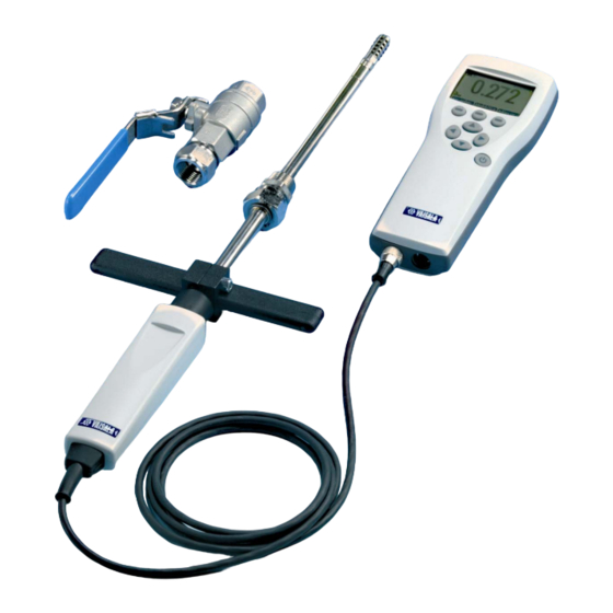
MM70 consists of two main units: MI70 indicator and MMP78 probe. MM70 Hand-held humidity meter incorporates Vaisala's advanced ® HUMICAP technology which enables reliable and high performance moisture in oil measurement. Vaisala MM70 is delivered with a factory calibration certificate. VAISALA ________________________________________________________________________ 9... -
Page 12: Structure Of The Mi70 Indicator
USER'S GUIDE____________________________________________________________________ Structure of the MI70 Indicator 0605-094 Figure 1 MI Indicator The following numbers refer to Figure 1 on page 10. MI70 indicator Recharger connector Power On/Off key Connector port for cable Connector port for probe 10 __________________________________________________________________ M210498EN-C... -
Page 13: Structure Of The Mmp78 Probe
Clasp nut Fitting body Tools 0605-082 Figure 3 Protecting Cap and Plastic Wrench The following numbers refer to Figure 3 on page 11: Protecting cap (including plastic wire for attaching the cap to the probe) Plastic wrench VAISALA _______________________________________________________________________ 11... -
Page 14: Display Parameters
Windows environment on a PC display. The data can even be transferred further to a spreadsheet software (such as Microsoft Excel) for modification. The MI70 Link Software can be ordered from Vaisala. For more information, see section Options and Accessories Available on page 66. - extension cable (10m) -
Page 15: Installation And Mounting Options
Connect the probe to either one of the bottom connectors of the indicator. To ensure durable connection, screw the metal ring clockwise until it tightens up. (Respectively, when disconnecting the cable, first screw the metal ring counterclockwise until it loosens and then pull out the plug.) VAISALA _______________________________________________________________________ 13... -
Page 16: Installing The Probe
USER'S GUIDE____________________________________________________________________ Press the power on/off key. Select the language by using the arrow up/down keys. Confirm by pressing the SELECT key. You can select the language later on, as well. For more information, see Selecting Language on page 27. To change the date, select Date and press the SET key. -
Page 17: Tightening The Clasp Nut
Tighten the clasp nut first manually. Mark the fitting screw and the clasp nut. Tighten the nut a further 30 - 40° (ca.1/12" turn) with a plastic wrench. If you have a suitable torque spanner, tighten the nut to max 35±5 Nm (25±4 ft-lbs). VAISALA _______________________________________________________________________ 15... -
Page 18: Figure 5 Tightening Clasp Nut
USER'S GUIDE____________________________________________________________________ 0605-080 Figure 5 Tightening Clasp Nut The following numbers refer to Figure 5 on page 16 above Probe Clasp nut Fitting screw NOTE Take care not to over tighten the clasp nut to avoid difficulties when opening it. When the probe is used in a pressurized processes the sensor head should preferebly be installed through a ball valve assembly. -
Page 19: Ball Valve Installation
Ball Valve Installation The ball valve installation is preferred when connecting the probe to a pressurized process or pipeline. Use the Vaisala BALLVALVE-1 ball valve set or a 1/2" ball valve assembly with a ball hole of 14 mm or more. -
Page 20: Figure 7 Ball Valve Installation
USER'S GUIDE____________________________________________________________________ Make sure that the temperature at the measurement point is equal to that of the process, otherwise the moisture reading may be incorrect. 0605-085 Figure 7 Ball Valve Installation The following numbes refer to Figure 7 on page 18 above. Probe Clasp nut. -
Page 21: Mounting The Probe For Direct Measurement (No Pressure)
0605-088 Figure 8 Direct Mounting The following numbers refer to Figure 8 on page 19 above: Lift up the clasp nut Pull down to clean the probe VAISALA _______________________________________________________________________ 19... - Page 22 USER'S GUIDE____________________________________________________________________ This page intentionally left blank. 20 __________________________________________________________________ M210498EN-C...
-
Page 23: Menu Operations And Settings
The following numbers refer to Figure 9 on page 21 above: To open the main menu, first press any of the arrow keys (3), then press the middlemost function key (1). Function keys left/middle/right Arrow keys up/down/left/right Power On/Off key VAISALA _______________________________________________________________________ 21... -
Page 24: Basic Display
USER'S GUIDE____________________________________________________________________ - To turn the indicator on or off, press the power On/Off key. - To open the main menu, press any of the arrow keys and then the middlemost function key in sequence. - To move in a menu and select an option, press the up/down arrow keys. -
Page 25: Graphical Display
If this happens, press any of the arrow keys to re-enter main menu. Open a sub-menu with the right arrow key. To return to the previous menu level, press the left arrow key. To return to the basic display, press the EXIT key. VAISALA _______________________________________________________________________ 23... -
Page 26: Settings
USER'S GUIDE____________________________________________________________________ Settings Display Settings 0605-102 Figure 11 Display Setting Menus Quantities and Units Open the MENU: First press an arrow key, and then press the OPEN key. Select Display. Press the right arrow key. Select Quantities and Units. Press the right arrow key. Select the desired quantity with the up/down arrow keys and press the SELECT key. -
Page 27: Hold/Save Display
To return to the basic display, press the EXIT key. Graphic History Graphic history shows the data curve of the last hour. To see longer graphs, use the data recording function to save the data and then view it as a graph. VAISALA _______________________________________________________________________ 25... -
Page 28: User Interface Settings
USER'S GUIDE____________________________________________________________________ Open the MENU. First press the right arrow key, and then press the OPEN key. Select Display. Press the right arrow key. Select Graphic History. To enter a graphical history display, press the SHOW key. To get the statistical info on the graph area (minimum, maximum and mean values), press the INFO key. -
Page 29: Selecting Language
Select User Interface. Press the right arrow key. Select Auto Power off. Press the SET key. Select the desired option. Press the SELECT key. To return to the basic display, press the CANCEL key and the EXIT key. VAISALA _______________________________________________________________________ 27... -
Page 30: Changing The Shorcut Keys
USER'S GUIDE____________________________________________________________________ Changing the Shorcut Keys As a default, the function keys are shortcuts to Graphic, Hold/Save and Record menus. The shortcuts can be changed to other locations to correspond your needs. Open the MENU. First press the right arrow key, and then press the OPEN key. -
Page 31: Device Information
Select Device Information. Press the SHOW key. Information on the MI70 Indicator is displayed. To enter Probe Information, press the MORE key. To return to the basic display, first press the OK key and then the EXIT key. VAISALA _______________________________________________________________________ 29... -
Page 32: Restoring Factory Settings
USER'S GUIDE____________________________________________________________________ 0605-099 Figure 14 Device Information Submenus Restoring Factory Settings Factory settings can be reverted to clear all changed settings and data memory of the indicator. Reverting factory settings does not effect on probe calibration. Open the MENU. First press the right arrow key, and then press the OPEN key. -
Page 33: Calculation Model With Oil Specific Coefficients
The determination of specific coefficients shall be agreed with the Vaisala representative. The determined coefficients of the transformer oil can be programmed to the MM70 by Vaisala or by a user according to the following instructions. Calculation Model with Oil Specific Coefficients is always needed NOTE for silicone based oils. -
Page 34: Other Functions
USER'S GUIDE____________________________________________________________________ Select the B value (B:0.0000) and press the SET key. Set the value B by using the arrow keys up/down/left/right, press the OK key. You may key in coefficients for 4 different oils. Identify the oil by numbering them (1...4). Select the first row (H ) and set the identification number. - Page 35 OK key. To reactivate the alarm function, answer YES. To stop the alarm function completely, answer NO. NOTE The alarm is not in function when the device is turned off. Remember to turn off the automatic power off, see Automatic Power Off on page VAISALA _______________________________________________________________________ 33...
-
Page 36: Selecting And Scaling The Analog Output
USER'S GUIDE____________________________________________________________________ Selecting and Scaling the Analog Output 0605-093 Figure 17 Analog Output Menus To get analog measurement data, you need the analog output signal cable, see section Options and Accessories Available on page 66. One voltage signal channel 0...1.0V can be scaled for the selected quantity. Connect the analog output signal cable connector to the indicator base connector. -
Page 37: Taking Measurements
Measuring Other Parameters Simultaneously The MI70 indicator is a generic indicator that can be used with Vaisala interchangeable humidity (HMP), dewpoint (DMP) and carbon dioxide (GMP) probes. Two different probes can be used simultaneously. -
Page 38: Recording Data
USER'S GUIDE____________________________________________________________________ Connect the DMP70/GMP70/HMP70 probe to the other connector port in the bottom of the indicator. Turn on the device. Check that the pressure settings of the probes (port I and II) are the same, if you are taking measurements from the same condition. -
Page 39: Stopping Recording
Select the measurement interval with the arrow keys. Measurement intervals and maximum recording times are shown in the Table 1 above. You can save individual measurement data points with Hold/Save function. For more information, see section Hold/Save Display on page 25. VAISALA _______________________________________________________________________ 37... -
Page 40: Viewing Recorded Data
USER'S GUIDE____________________________________________________________________ Viewing Recorded Data Open the MENU. First press the right arrow key, and then press the OPEN key. Select Recording/Viewing. Press the right arrow key. Select View recorded data. Press the right arrow key. Select the file that you want to view, press the right arrow key. The files are identified according to the starting date and time of recording. -
Page 41: Transferring Recorded Data To Pc
Transferring Recorded Data to PC The recorded data can be transferred to a PC using the MI70 Link program. The MI70 Link program can be ordered from Vaisala, see section Options and Accessories Available on page 66. You can examine the recorded data easily in the Microsoft Windows®... - Page 42 USER'S GUIDE____________________________________________________________________ This page intentionally left blank. 40 __________________________________________________________________ M210498EN-C...
-
Page 43: Calibration And Adjustment
Adjustment of Transmitters Using MM70 in Checking and Adjusting Vaisala´s HMP228, MMT318 and MMT330 series transmitters can be calibrated and adjusted by using MM70. - In the field: Check and adjust a fixed transmitter´s reading against MM70´s calibrated reference probe. -
Page 44: Calibration And Adjustment Of Hmp228 Series Transmitters
USER'S GUIDE____________________________________________________________________ Calibration and Adjustment of HMP228 Series Transmitters You can check all the parameters a , T and RH, but only RH can be adjusted. You can calibrate your transmitter against a calibrated reference probe of MM70 or against a calibrator's reference humidity by using MI70 indicator in communication. -
Page 45: Relative Humidity Adjustment By Using A Calibrated Reference Probe
EXIT key twice. 1-point Relative Humidity Adjustment by Using a Calibrator You can use Vaisala humidity calibrator HMK15 to achieve the reference humidities. MI70 indicator is working as a communicator in the calibration procedure. When using this adjustment method, start with the steps 1 through 12 on the previous page. -
Page 46: 2-Point Relative Humidity Adjustment By Using A Calibrator
EXIT key twice. 2-point Relative Humidity Adjustment by Using a Calibrator You can use Vaisala humidity calibrator HMK15 in calibration and adjustment. Note that the difference between the two reference humidities should be at least 50%. MI70 indicator is working as a communicator in the calibration procedure. -
Page 47: Calibration And Adjustment Of Mmt318 Transmitters
Field Checking and Adjustment by Using a Calibrated Reference Probe When using this adjustment method, start with the steps 1 through 4 in the section Calibration and Adjustment of MMT318 Transmitters on page 45. Then proceed as follows: VAISALA _______________________________________________________________________ 45... -
Page 48: 1-Point Adjustment By Using A Calibrator
USER'S GUIDE____________________________________________________________________ Select a , RH, T or H O (H O can only be checked, not adjusted). Press the SELECT key. Check that the probes are located in equal conditions and wait until the readings are stabilized (can take 30 minutes or more). If you are near the probes, do not breathe towards them. -
Page 49: 2-Point Adjustment By Using A Calibrator
Note that if the difference between two references is less than 50%, adjustment cannot be done. Adjustment is done. To return to the basic display, first press the BACK key, then the EXIT key. Detach the calibration cable. VAISALA _______________________________________________________________________ 47... -
Page 50: Calibration And Adjustment Of Mmt330 Transmitters
USER'S GUIDE____________________________________________________________________ Calibration and Adjustment of MMT330 Transmitters You can check and adjust MMT330 transmitter reading against a calibrated reference probe of MMP78 or against another reference condition by using MI70 indicator in communication. Follow the first 4 steps and continue according to the chosen calibration method. Connect the 211339-connection cable between the service port of the MMT330 transmitter and the bottom connector of the MI70 indicator. -
Page 51: 1-Point Adjustment By Using A Calibrator
Enter correct reference value by using the arrow keys. Press the OK key. Confirm by pressing the YES key. Adjustment is done. To return to the basic display, first press the BACK key, then the EXIT key. Detach the calibration cable. VAISALA _______________________________________________________________________ 49... -
Page 52: 2-Point Adjustment By Using A Calibrator
USER'S GUIDE____________________________________________________________________ 2-point Adjustment by Using a Calibrator When using this adjustment method, start with the steps 1 through 4 in the section Calibration and Adjustment of MMT330 Transmitters on page 48. Then proceed as follows: Select the quantity and press the SELECT key. Remove the filter from the transmitter´s probe and insert the probe head into the reference condition. -
Page 53: Calibration And Adjustment Of Mm70 Series Probes
The recommended calibration interval is one year. It is recommended to send the device to Vaisala Service Centre for calibration and adjustment, see contact information in section Vaisala Service Centers on page 61. Alternatively, user can calibrate and adjust MM70 by following the instructions below. -
Page 54: 2-Point Adjustment
USER'S GUIDE____________________________________________________________________ have to feed the reference values, the MM70 displays the accurate value based on the measured temperature and the Greenspan table stored into the memory of the MM70. Make the adjustment as instructed in the section below (select LiCl-NaCl autom. on item 8 and follow the display instructions). -
Page 55: 1-Point Adjustment
When pressing the key, indicator turns to adjusting mode. Select T, press the SELECT key. Now the adjustment mode is on, press the ADJUST key to select the adjustment method: 1-point adjustment or 2-point adjustment. VAISALA _______________________________________________________________________ 53... -
Page 56: 1-Point Adjustment
USER'S GUIDE____________________________________________________________________ 1-point Adjustment When using this adjustment method, start with the steps 1 through 4 in the previous section Temperature Adjustment on page 53. Then proceed as follows. Select 1-point adjustment, press the SELECT key. Set the probe to a reference temperature. You can follow the stabilization from the graph display. -
Page 57: Last Adjustment Date
- a temperature test chamber - for example, a conical flask (1L) sealed by PTFE stopper with an inlet for a moisture probe - MMT330 by Vaisala - magnetic stirrer. Procedure: Define the water content of the oil sample with the titration. Use the oil moisture level that is close to real conditions in the process. -
Page 58: Table 2 Example: Measured Water Content 213 Ppm
USER'S GUIDE____________________________________________________________________ NOTE If the oil sample is very dry and the temperatures are close to each other, it may cause inaccuracy to the calculation model. In order to get the best possible performance it is recommended to use oil conditions that represent real conditions in application. -
Page 59: Error Messages
If MM70 displays an error message, first check that the sensor is connected properly and let the probe dry if there is condensed water in the probe. In case of constant error, please contact Vaisala Service Center. For more information, see Vaisala Service Centers on page 61. Error Message Types... - Page 60 USER'S GUIDE____________________________________________________________________ This page intentionally left blank. 58 __________________________________________________________________ M210498EN-C...
-
Page 61: Chapter 6 Maintenance
Immerse the probe head into heptane liquid and rinse out the oil. Dry the probe head with instrument air. In case you are going to calibrate the probe, remove the filter and dry the sensor with instrument air. Check that the sensor looks clean. VAISALA _______________________________________________________________________ 59... -
Page 62: Changing The Battery
USER'S GUIDE____________________________________________________________________ Changing the Battery A new rechargeable battery pack can be ordered from Vaisala. Change the battery pack as follows: Open the back plate of the indicator by opening the screw of the back plate. Remove the old battery pack. Detach the black connector by gently pulling it up from the wires. -
Page 63: Vaisala Service Centers
Chapter 6 ___________________________________________________________ MAINTENANCE Vaisala Service Centers VAISALA _______________________________________________________________________ 61... - Page 64 USER'S GUIDE____________________________________________________________________ This page intentionally left blank. 62 __________________________________________________________________ M210498EN-C...
-
Page 65: Technical Specifications
Temperature Measurement range -40...+100 C (-40 ...+212 F) Typical accuracy at +20 C (+68 C) 0.1 C (0.18 F) Typical temperature dependence of 0.005 C/C (0.003 F/F) electronics Temperature sensor Pt 100 RTD 1/3 Class B IEC VAISALA _______________________________________________________________________ 63... -
Page 66: Mmp78 Probe
USER'S GUIDE____________________________________________________________________ MMP78 Probe Humidity sensor HUMICAP Temperature sensor Pt 100 1/3 Class B IEC 751 Operating temperature range for -40...+60 C, -40...+140 F electronics Operating pressure range 0...20 bar Standard sensor protection Stainless steel grid Housing classification IP65 (NEMA 4) Housing material ABS/PC blend Probe material... -
Page 67: Battery Pack
Temperature Meter Storage temperature -40...+70 C Storage humidity range 0...100% Non-condensing Electromagnetic Compatibility Complies with the following standard: EN 61326-1:1997+Am 1:1998, Electrical equipment for measurement, control and laboratory use - EMC requirements: Portable test and measurement equipment. VAISALA _______________________________________________________________________ 65... -
Page 68: Options And Accessories Available
USER'S GUIDE____________________________________________________________________ Options and Accessories Available Table 3 List of Options and Accessories Description Order code AC-Adapters Euro AC-adapter MI70EUROADAPTER UK AC-adapter MI70UKADAPTER US AC-adapter MI70USADAPTER AUS AC-adapter MI70AUSADAPTER Cables Analog output signal cable 27168ZZ Connection cable for MMT318 DRW216050 Connection cable for HMP228 27159ZZ Connection cable for MMT330... -
Page 69: Dimensions In Mm (Inches)
Chapter 7 ______________________________________________ TECHNICAL SPECIFICATIONS Dimensions in mm (inches) Figure 21 MI70 Indicator VAISALA _______________________________________________________________________ 67... -
Page 70: Figure 22 Mmp78 Probe
USER'S GUIDE____________________________________________________________________ 170 (6.69) Figure 22 MMP78 Probe 68 __________________________________________________________________ M210498EN-C... - Page 71 *M210498EN*...
Need help?
Do you have a question about the HUMICAP MM70 and is the answer not in the manual?
Questions and answers