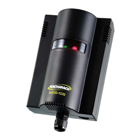
Bacharach MGS-150 Installation And Operation Manual
Gas detector
Hide thumbs
Also See for MGS-150:
- Installation and operation manual (36 pages) ,
- Installation manual (2 pages)

Related Manuals for Bacharach MGS-150


Summary of Contents for Bacharach MGS-150
- Page 1 Gas Detector Installation and Operation Manual Instruction 6309-9000 Revision 2 – February 2013 Product Leadership • Training • Service • Reliability...
- Page 2 WARRANTIES). SHOULD YOUR INSTRUMENT REQUIRE NON-WARRANTY REPAIR, YOU MAY CONTACT THE DISTRIBUTOR FROM WHOM IT WAS PURCHASED OR YOU MAY CONTACT BACHARACH DIRECTLY. IF BACHARACH IS TO DO THE REPAIR WORK, SEND THE INSTRUMENT, PREPAID, TO BACHARACH, INC. AT THE FOLLOWING ADDRESS. BACHARACH, INC.
- Page 3 TO COPYRIGHT PROTECTION. ALL RIGHTS ARE RESERVED. NO PARTY MAY USE OR COPY SUCH SOFTWARE IN ANY MANNER OR FORMAT, EXCEPT TO THE EXTENT THAT BACHARACH GRANTS THEM A LICENSE TO DO SO. IF THIS SOFTWARE IS BEING LOADED ONTO MORE THAN ONE COMPUTER, EXTRA SOFTWARE LICENSES MUST BE PURCHASED.
-
Page 4: Table Of Contents
MGS-150 Manual Table of Contents Section 1. Overview ..................5 1.1. General Information..................5 1.2. Technical Specifications ................6 Section 2. Installation and Wiring..............8 2.1. General Placement Guidelines ..............9 2.2. Components and Access Overview .............. 9 2.3. Machinery Rooms ..................12 2.4. -
Page 5: Overview
Overview 1.1. General Information The MGS-150 is a state-of-the-art fixed gas detector which can detect a wide range of different gases. The gas sensors can be used on a stand- alone basis or integrated into Controls or Building Management Systems (BMS). -
Page 6: Technical Specifications
MGS-150 Manual 1.2. Technical Specifications Specification Description Power Supply 12-24 VDC, 12-24 VAC 50/60 Hz, 2 W max. Power Monitoring Green LED Visual Alarm Red LED Audible Alarm Buzzer, enable/disable Fault Monitoring Red LED (on); Green LED (off) Analog Outputs 4-20 mA;... - Page 7 MGS-150 Manual NOTE: The hazardous area EXd Gas Monitor products are designed with individually certified EXd main housing enclosures and certified EXD remote or attached sensor enclosures. The main housing enclosure and its PCB assembly are also EXd certified, but the final EXd Gas Monitor assemblies (main enclosure and/or sensor assembly) are not currently EXD certified, but are pending additional testing.
-
Page 8: Installation And Wiring
MGS-150 Manual Section 2. Installation and Wiring WARNING: Explosion hazard! Do not mount the MGS in an area that may contain flammable liquids, vapors, or aerosols. Operation of any electrical equipment in such an environment constitutes a safety hazard. CAUTION: The MGS contains sensitive electronic components that can be easily damaged. -
Page 9: General Placement Guidelines
MGS-150 Manual 2.1. General Placement Guidelines NOTE: The MGS-150 should be installed plumb and level and securely fastened to a rigid mounting surface. Sensors must be located within the appropriate wire lengths from the central control unit (if used). In all cases the sensor supplied is designed for maximum sensitivity to a particular gas. - Page 10 MGS-150 Manual Figure 2. EC or IR Sensor Components and Wiring 6309-9000 Rev 2...
- Page 11 MGS-150 Manual Figure 3. SC Sensor Components and Wiring 6309-9000 Rev 2...
-
Page 12: Machinery Rooms
MGS-150 Manual Item Description Enclosure To open the standard sensor enclosure, turn the cable Access clamp 1/2 turn counter-clockwise to loosen the internal nut, depress the clip on top of the enclosure and open. Reverse to close. Power 12-24V AC/DC, connect at positions 0V and +V at connector block CN1. - Page 13 MGS-150 Manual most common leak sources are valves, gauges, flanges, joints (brazed or mechanical), filling or draining connections, etc. • When mechanical or natural ventilation is present, mount a sensor in the airflow. • In machinery rooms where there is no discernable or strong...
-
Page 14: Refrigerated Spaces
MGS-150 Manual 2.4. Refrigerated Spaces In refrigerated spaces, sensors should be located in the return airflow to the evaporators on a sidewall (below head-high is preferred), or on the ceiling, not directly in front of an evaporator. In large rooms with multiple evaporators, sensors should be mounted on the central line between 2 adjacent evaporators, as turbulence will result in airflows mixing. -
Page 15: Air Conditioning (Direct Systems Vrf/Vrv)
MGS-150 Manual 2.6. Air Conditioning (Direct Systems VRF/VRV) For compliance with EN378, at least one detector shall be installed in each occupied space being considered and the location of detectors shall be chosen in relation to the refrigerant and they shall be located where the refrigerant from the leak will collect. -
Page 16: Remote Sensor Head Installation
The MGS and remote sensor must be kept together as they are calibrated together and are a matched pair. To clean, the faceplate should be lightly dusted. IMPORTANT: Do not spray the MGS-150 with cleaning or polishing aerosols. 6309-9000 Rev 2... -
Page 17: Housing Dimensions
MGS-150 Manual Section 3. Housing Dimensions Figure 4. MGS-150 Standard Housing 6309-9000 Rev 2... - Page 18 MGS-150 Manual Figure 5. IP66 Housing with Splashguard 6309-9000 Rev 2...
- Page 19 MGS-150 Manual Figure 6. IP66Airflow Duct Mount Housing Units = mm Figure 7. Exd Housing 6309-9000 Rev 2...
- Page 20 MGS-150 Manual 9.8 feet (3 meters) Typical For Dimensions and Mounting Locations , See Figure 5. Figure 8. IP66 Housing with Remote Sensor Head NOTE: For the Exd Remote Sensor Head and 16.4 ft (5 m) cable, the thread varies based on the model.
-
Page 21: Operation And Stabilization
MGS-150 Manual Section 4. Operation and Stabilization On powering up, the MGS-150 will sense for the presence of gas after an initial warm-up delay of 5 minutes. The green LED will flash at 1 second intervals during the warm-up. In an alarm condition: •... -
Page 22: Configurations
MGS-150 Manual Section 5. Configurations 5.1. Overview Function Description Time Delay Available on the audible alarm and relay to avoid false alarms. This is set with jumpers. The default delay is 0 minutes. You may wish to set to 15 minutes during start up. -
Page 23: Functional Tests And Calibration
In applications where life safety is critical, calibration should be done quarterly (every 3 months) or on a more frequent basis. Bacharach is not responsible for setting safety practices and policies. Safe work procedures including calibration policies are best determined by company policy, industry standards, and local codes. - Page 24 MGS-150 Manual IMPORTANT: Failure to test or calibrate the unit in accordance with applicable instructions and with industry guidelines may result in serious injury or death. manufacturer is not liable for any loss, injury, or damage arising from improper testing, incorrect calibration, or inappropriate use of the unit.
-
Page 25: Bump Testing
MGS-150 Manual Exposing the sensor to a gas and observing its response to the gas. The objective is to establish if the sensor is reacting to the gas and all the sensor outputs are working correctly. There are two types of bump test. - Page 26 MGS-150 Manual NOTE: Prior to carrying out a bump test, check and adjust the zero setting as described in the Calibration section. NOTE: Procedures for bump test and calibration vary depending on the sensor technology used and the gas in question.
- Page 27 MGS-150 Manual Figure 9. Gas Cylinder and Test Hardware Gas ampoules are convenient and inexpensive alternatives to using gas cylinders for bump testing. Step Bump Testing Using Gas Ampoules Make sure that both the ampoules and the calibration beaker are clean and dry.
-
Page 28: Calibration Overview
0V and VS using a 0-5V scale. If the sensor range is 0-1000 ppm, then 5V=1000 ppm. Bacharach offers a calibration kit that consists of a calibration gas cylinder, a flow regulation valve with flexible non-absorbent tubing and vented calibration hood. Tools required: •... -
Page 29: Calculating Calibration Voltage
MGS-150 Manual 6.4. Calculating Calibration Voltage Sensor outputs are linear. As long as you have a gas cylinder of known concentration you can calibrate to any desired range. Example: For a sensor range of 0-1000 ppm and a cylinder of the target ��... -
Page 30: Calibrating Electrochemical (Ec) Sensors
MGS-150 Manual 6.6. Calibrating Electrochemical (EC) Sensors There are two adjustments required: zero and span. They are monitored at 0V and VS using a 0-5V scale. If the sensor range is 0-1000 ppm, then 5V=1000 ppm. Step Calibrating Electrochemical (EC) Sensors Locate Pot VR201 which is used to adjust the zero point. -
Page 31: Troubleshooting
Symptom Possible Cause(s) • Check power supply. Check wiring. Green and Red light • MGS-150 was possibly damaged in transit. Check by installing another MGS-150 to confirm the fault. • Sensor may be disconnected from Red light on, green led printed circuit board. -
Page 32: Ce Declaration Of Conformity
(EMC) Standard IEC61010-1: 2010 Safety Standard EN61010-1: 2010 Signature: Name: Doug Keeports Title: VP of Product Development Date: 7 August 2012 The technical documentation file required by this directive is maintained at the corporate headquarters of Bacharach, Inc. 6309-9000 Rev 2... - Page 33 MGS-150 Manual 6309-9000 Rev 2...
- Page 34 MGS-150 Manual 6309-9000 Rev 2...
- Page 35 MGS-150 Manual 6309-9000 Rev 2...
- Page 36 MGS-150 Manual World Headquarters 621 Hunt Valley Circle, New Kensington, Pennsylvania 15068 Phone: 724-334-5000 • Toll Free: 1-800-736-4666 • Fax: 724-334-5001 Website: www.MyBacharach.com • E-mail: help@MyBacharach.com 6309-9000 Rev 2...
Need help?
Do you have a question about the MGS-150 and is the answer not in the manual?
Questions and answers