Friedrich MC24Y3F Service Manual
Cassette type (60hz)
Hide thumbs
Also See for MC24Y3F:
- Specifications (2 pages) ,
- Specifications (1 page) ,
- Brochure & specs (29 pages)
Table of Contents
Advertisement
Quick Links
SPLIT TYPE
AIR CONDITIONER
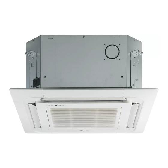
CASSETTE
Models
Indoor unit
MC24Y3F
C ONT E NTS
SPECIFICATIONS . . . . . . . . . . . . . . . . . . . . . . 1
DIMENSIONS . . . . . . . . . . . . . . . . . . . . . . . . . . 2
REFRIGERANT SYSTEM DIAGRAM . . . . . . . 4
CIRCUIT DIAGRAM . . . . . . . . . . . . . . . . . . . . . 5
INDOOR PCB CIRCUIT DIAGRAM . . . . . . . .
ERROR CONTENTS . . . . . . . . . . . . . . . . . . . .
DISASSEMBLY ILLUSTRATION . . . . . . . . . . 13
PARTS LIST . . . . . . . . . . . . . . . . . . . . . . . . . . 21
STANDARD ACCESSORIES . . . . . . . . . . . . . 23
type
(60Hz)
Outdoor unit
MR24UY3F
. . . . . . 8
7
11
Advertisement
Table of Contents

Related Manuals for Friedrich MC24Y3F


Summary of Contents for Friedrich MC24Y3F
-
Page 1: Table Of Contents
CASSETTE Models Indoor unit Outdoor unit MC24Y3F MR24UY3F C ONT E NTS SPECIFICATIONS ..... . 1 DIMENSIONS ......2 REFRIGERANT SYSTEM DIAGRAM . -
Page 2: Specifications
H x W x D WEIGHT INDOOR UNIT Gross / Net OUTDOOR UNIT Gross / Net 2006.05.25 COOLING & HEATING MC24Y3F MR24UY3F 22,200 / 22,200 BTU/h 24,200 / 24,200 BTU/h 230 / 208 V 60Hz 9.2 / 10.1 A 10.4 / 11.4 A 2.10 / 2.10 kW... -
Page 3: Dimensions
D I M E NS I O N S INDOOR UNIT unit : inch (mm) 37" (940) Drain inside Dia. ø1-1/4" (ø32) outside Dia. ø1-1/2" (ø37) 11-3/4" (298.5) 12" (305.5) 9-25/32" (248.5) 2006.05.18 29-17/32" (750) 32-3/4" (830) 11-3/4" (298.5) 12" (305.5) 9-25/32"... -
Page 4: Outdoor Unit
OUTDOOR UNIT unit : inch (mm) 2006.05.18 3"(77) 35-1/2" (900) Air Flow 25-5/8" (650) 1-1/4" 1/2" (31) (12) 13" (330) 15-3/4" (400) 5-3/4" (147) 6-3/4" (170) -
Page 5: Refrigerant System Diagram
R EFR I G E R A N T SYSTEM DIAGRAM OUTDOOR UNIT High Pressure Switch Condenser Strainer : COOL : HEAT 2006.05.18 Pressure Refrigerant Pipe Check Valve 15.88mm (5/8") Charging Valve 4-way Valve Accumulator Compressor Expansion Refrigerant Pipe Valve 9.52mm (3/8") Strainer Charging Valve... -
Page 6: Circuit Diagram
C I RC U I T DIA GRAM INDOOR UNIT TO REMOTE CONTROL UNIT TERMINAL POWER SUPPLY PCB ASSY TO OUTDOOR UNIT 2006.05.18 BROWN ORANGE YELLOW WHITE WHITE BLACK BLACK BLACK BLACK BLACK BLACK WHITE WHITE BLACK BLACK WHITE PURPLE BLUE WHITE WHITE... - Page 7 OUTDOOR UNIT PIPE TEMPERATURE THERMISTOR DISCHARG TEMPERATURE THERMISTOR CONNECTOR WHITE COMPRESSOR BLACK ACTIVE FILTER MODULE TERMINAL BLACK WHITE BLACK BROWN CHOKE COIL 2006.05.18 BLACK BROWN EMI FILTER CN21 CN22 CN23 CN26 CN25 W305 WHITE W304 FUSE F4 T 5A-250V BLACK W303 BROWN CONTROLLER PCB ASSY...
-
Page 8: Indoor Pcb Circuit Diagram
IN D O O R PCB CIR CUIT D IAG R A M CONTROLLER PCB ASSEMBLY Model : MC24Y3F K01AL-050LHSE-C1 2006.05.25... -
Page 9: Outdoor Pcb Circuit Diagram
OUTD O O R P C B CI RCUI T DI AGR AM INVERTER ASSEMBLY EZ-005FHUE Model : MR24UY3F POWER SUPPLY PCB ASSY K04BA-0500HUE-P0 CONTROLLER PCB ASSY K04AW-0502HUE-C1 2006.05.25... - Page 10 Model : MR24UY3F CONTROLLER PCB ASSEMBLY K04AW-0502HUE-C1 600/450V x 4 2006.05.25...
- Page 11 Model : MR24UY3F BLACK VA101 470V <TNR> POWER SOURCE VA102 230V 470V 60Hz <TNR> WHITE BLACK TO INDOOR UNIT WHITE EARTH GREEN BLACK AC VOLT OUT WHITE 2006.05.25 POWER SUPPLY PCB ASSEMBLY K04BA-0500HUE-P0 TM100 N200500K1D7C RCH4730-021PF07 C104 0.033 C101 <YE> C105 <LE>...
-
Page 12: Error Contents
ER RO R C O N TE NTS (indoor unit) (1) Stop the air conditioner operation. (2) Press the master control button and the fan control button simultane- ously for 2 seconds or more to start the test run. (3) Press the start/stop button to stop the test run. - Page 13 E RRO R CO NTEN TS (outdo or u ni t ) 1. Make a TEST RUN in accordance with the in- stallation instruction sheet for the indoor unit. 2. OUTDOOR UNIT LEDS When a malfunction occurs in the outdoor unit, the LED on the circuit board lights to indicate the error.
-
Page 14: Disassembly Illustration
834-2 2006.05.25 876-2 472-4 253-A 481-1 472-5 472-5 D I S A S S E MB L Y I L L U S T R A T IO N INDOOR UNIT 472-2 777-2 472-3 472-5 472-5 472-1 777-1... - Page 15 INDOOR UNIT 460-1 460-2 835 482 2006.05.18 815-1 541-1 476-2 337-1 834-1 337-2 337-1 146-2 146-1...
- Page 16 INDOOR UNIT 815-2 320-1 320-1 381-4 381-4 731-2 2006.05.18...
- Page 17 INDOOR UNIT 184-1 2006.05.18...
- Page 18 OUTDOOR UNIT 2006.05.25...
- Page 19 OUTDOOR UNIT 2006.05.25...
- Page 20 OUTDOOR UNIT 2006.05.24...
- Page 21 OUTDOOR UNIT 33 34 2006.05.18...
-
Page 22: Parts List
Cabinet-B Assy Drain Port M10 Nut-A (Large) M10 Nut-B (Small) 472-1 RFM (Grille)-A 472-2 RFM (Grille)-B 2006.06.13 Part No. Ord. Ref. MC24Y3F Q'ty 67200589 472-3 RFM (Grille)-C 67220259 472-4 RFM (Grille)-D 67200591 472-5 RFM (Grille)-E 67200557 Turbo Fan Assy 67200555... -
Page 23: Outdoor Unit
OUTDOOR UNIT Ref. ---- ---- ---- ---- ---- ---- ---- ---- ---- ---- ---- ---- ---- ---- ---- ---- 2006.05.25 Part No. Description MR24UY3F Top Panel Sub Assy 67201640 Front Panel 67201601 Fan Guard 67201602 Grip Side 67201603 Service Panel Sub Assy 67201688 Right Panel 67201605... -
Page 24: Standard Accessories
2006.05.25 STA N DA R D A C C ESSOR IE S INDOOR UNIT ACCESSORIES Name and Shape Q’ty Coupler heat For indoor side pipe joint insulation Tapping Screw For installing the remote (flush heads) controller Special nut A For installing indoor unit (large flange) Special nut B For installing indoor unit... - Page 25 0605G3089...
Need help?
Do you have a question about the MC24Y3F and is the answer not in the manual?
Questions and answers