Honeywell TB7220U CommercialPRO Installation Instructions Manual
Programmable thermostat
Hide thumbs
Also See for TB7220U CommercialPRO:
- Owner's manual (32 pages) ,
- Installation instructions manual (17 pages)
Table of Contents
Advertisement
TB7220U
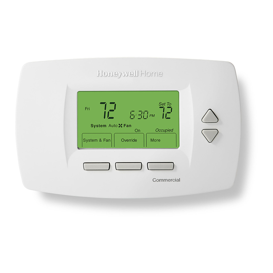
CommercialPRO™
Programmable Thermostat
APPLICATION
The TB7220U Programmable Thermostat provides electronic control of 24 Vac heating and cooling systems.
See Table 1 for a description.
Feature
Powering Methods
System Types
Changeover
System Setting
Fan Setting
MERCURY NOTICE
If this control is replacing a control that contains
mercury in a sealed tube, do not place your old
control in the trash. Dispose of properly.
Contact your local waste management authority
for instructions regarding recycling and the
proper disposal of an old control.
INSTALLATION
When Installing this Product...
1. Read these instructions carefully. Failure to follow
them could damage the product or cause a
hazardous condition.
2. Check ratings given in instructions and on the
product to ensure the product is suitable for your
application.
Table 1. TB7220U Thermostat Description.
• Battery only
• Direct connection to a 24 Vac transformer only
• Direct connection to a 24 Vac transformer with battery backup
• Conventional (up to 2 Heat, 2 Cool stages)
• Heat Pump (up to 3 Heat, 2 Cool stages)
Manual or automatic changeover (selectable)
Heat-Off-Cool-Auto
Auto-On
INSTALLATION INSTRUCTIONS
Description
3. Installer must be a trained, experienced service
technician.
4. After installation is complete, check out product
operation as provided in these instructions.
CAUTION
Electrical Shock or Equipment Damage
Hazard.
Can shock individuals or short equipment
circuitry.
Disconnect power supply before installation.
Select Thermostat Location
Select a location for the thermostat about 5 ft (1.5m)
above the floor in an area with good air circulation at
average temperature. See Fig. 1.
62-0221-05
Advertisement
Table of Contents

Related Manuals for Honeywell TB7220U CommercialPRO


Summary of Contents for Honeywell TB7220U CommercialPRO
-
Page 1: Programmable Thermostat
TB7220U CommercialPRO™ Programmable Thermostat INSTALLATION INSTRUCTIONS APPLICATION The TB7220U Programmable Thermostat provides electronic control of 24 Vac heating and cooling systems. See Table 1 for a description. Table 1. TB7220U Thermostat Description. Feature Description Powering Methods • Battery only • Direct connection to a 24 Vac transformer only •... -
Page 2: Wiring
TB7220U COMMERCIALPRO™ PROGRAMMABLE THERMOSTAT 6. Insert the mounting screws into the wall anchors and tighten. DRILLED HOLES (2) WALL ANCHORS (2) 5 FEET [1.5 METERS] WALLPLATE MOUNTING M22258 SCREWS (2) M22268 Fig. 1. Select thermostat location. Fig. 3. Install wallplate. - Page 3 TB7220U COMMERCIALPRO™ PROGRAMMABLE THERMOSTAT WIRE WALLPLATE WALL OPENING SHADED AREA M22266 Fig. 5. Restrict wires to shaded area of wire hole. Table 2. Terminal Designation Descriptions. Terminal Designation Description RC (see Note 1) Power for cooling—connect to secondary side of cooling system transformer.
-
Page 4: Conventional System Wiring
TB7220U COMMERCIALPRO™ PROGRAMMABLE THERMOSTAT Conventional System Wiring (HOT) 24 VAC (HOT) 24 VAC OUTDOOR/INDOOR HEAT RELAY TEMPERATURE SENSOR HEAT RELAY ECONOMIZER OUTDOOR/INDOOR COMPRESSOR CONTACTOR TEMPERATURE POWER SUPPLY. PROVIDE DISCONNECT MEANS AND OVERLOAD SENSOR FAN RELAY PROTECTION AS REQUIRED. FACTORY INSTALLED JUMPER. - Page 5 TB7220U COMMERCIALPRO™ PROGRAMMABLE THERMOSTAT (HOT) (HOT) 24 VAC 24 VAC COOLING TRANSFORMER OUTDOOR/INDOOR FAN RELAY OUTDOOR/INDOOR TEMPERATURE COOL RELAY 1 COOL RELAY 2 TEMPERATURE SENSOR SENSOR COOL RELAY 1 COOL RELAY 2 HEAT RELAY 2 FAN RELAY (HOT) HEAT RELAY 2...
-
Page 6: Heat Pump System Wiring
TB7220U COMMERCIALPRO™ PROGRAMMABLE THERMOSTAT Heat Pump System Wiring (HOT) 24 VAC (HOT) 24 VAC CHANGEOVER VALVE OUTDOOR/INDOOR TEMPERATURE COMPRESSOR CONTACTOR SENSOR FAN RELAY CHANGEOVER VALVE OUTDOOR/INDOOR TEMPERATURE AUXILIARY HEAT RELAY ECONOMIZER COMPRESSOR CONTACTOR SENSOR FAN RELAY ECONOMIZER POWER SUPPLY. PROVIDE DISCONNECT MEANS AND OVERLOAD PROTECTION AS REQUIRED. -
Page 7: Sensor Wiring For Temperature Averaging
TB7220U COMMERCIALPRO™ PROGRAMMABLE THERMOSTAT Sensor Wiring for Temperature SUBBASE Averaging TR21 SUBBASE TR21 TR21 TR21-A TR21 TR21 TR21 THE TR21-A IS A 10K OHM SENSOR. M27483 Fig. 19. Wiring two TR21 (20K ohm) Sensors and one M27481 TR21-A (10K ohm) sensor to provide a temperature averaging network Fig. -
Page 8: Power The Thermostat
TB7220U COMMERCIALPRO™ PROGRAMMABLE THERMOSTAT POWER THE THERMOSTAT You can choose from three methods to power the thermostat: REMOVE • Batteries only (AA alkaline). • 24 Vac direct connection only. • 24 Vac direct connection with battery backup (AA alkaline). Wiring 24 Vac Common •... -
Page 9: Setting Calendar And Time
TB7220U COMMERCIALPRO™ PROGRAMMABLE THERMOSTAT SETTING CALENDAR AND TIME This thermostat is designed to, under normal use, automatically keep current time and day in memory for up to ten years once the calendar is set. There are two ways to set the calendar and time for this thermostat:... -
Page 10: Installer Setup Numbers, Settings, And Tests (Table 4)
TB7220U COMMERCIALPRO™ PROGRAMMABLE THERMOSTAT INSTALLER SETUP NUMBERS, SETTINGS, AND TESTS (TABLE 4) Configure Installer Setup CAUTION 1. Press and release the System key. 2. Press System and Done keys simultaneously. Equipment Damage Hazard. 3. Hold keys for approximately five seconds, until the Minimum compressor off time is bypassed screen changes. - Page 11 TB7220U COMMERCIALPRO™ PROGRAMMABLE THERMOSTAT Table 4. Installer Setup Menu. (Continued) Installer Setup Installer Setup Default Number Name Setting All Settings Notes 0240 CPH for first stage 1-12 Only shown for conventional system with heat conventional heat stages (ISU 0170). Selection in this stage changes default CPH of second stage heat.
- Page 12 TB7220U COMMERCIALPRO™ PROGRAMMABLE THERMOSTAT Table 4. Installer Setup Menu. (Continued) Installer Setup Installer Setup Default Number Name Setting All Settings Notes 0600 Heat Temperature 40 to 90°F (4 to 32°C) Only shown if system has heat stages (ISU 0170). Range Stops...
-
Page 13: Operation
TB7220U COMMERCIALPRO™ PROGRAMMABLE THERMOSTAT OPERATION System Settings Heat Pump Temperature Lockouts Heat—Thermostat controls the heating system. Off—Both heating and cooling systems are off. Dual Fuel Heat Pump and Outdoor Cool—Thermostat controls the cooling system. Sensor Auto—Thermostat automatically changes between heat and cool operation, depending on indoor temperature. -
Page 14: Troubleshooting (Table 7)
TB7220U COMMERCIALPRO™ PROGRAMMABLE THERMOSTAT TROUBLESHOOTING (TABLE 7) Table 7. Troubleshooting. Symptom Possible Cause Action Display does not come on. Thermostat is not being powered. Check for 24 Vac between C and RC. Check that AA batteries are installed correctly and are good. - Page 15 TB7220U COMMERCIALPRO™ PROGRAMMABLE THERMOSTAT Table 7. Troubleshooting. (Continued) Symptom Possible Cause Action Fan does not turn on in a call Fan Control in Heating is set to Gas or Set Fan Control in Heating to Electric for heat (electric furnace).
-
Page 16: Specifications
TB7220U COMMERCIALPRO™ PROGRAMMABLE THERMOSTAT SPECIFICATIONS Electrical Ratings: Thermostat Dimensions: 3-3/4 in. (95 mm) high x 6 in. (152 mm) wide x 1-3/8 in. (35 mm) deep. Voltage Running Terminal (50/60 Hz) Current Accessories: W (Heating) 20 - 30 Vac 0.02 - 1.0A C7089U Outdoor Sensor: 10K ohm NTC.