Advertisement
Quick Links
MCT-426, MCT-427
Supervised Wireless PowerCode Smoke / Heat and
Smoke Detector
1. DESCRIPTION AND APPLICATIONS
MCT-426 (photoelectric smoke detector) and MCT-427 (heat and
photoelectric smoke detector) are automatic fire detectors with integral
audible signal for open area protection, designed to sense heat or smoke
(not flame) and fitted with a PowerCode type UHF transmitter.
MCT-426 / MCT-427 provides early warning of developing fire by
sounding an alarm with its built-in alarm horn, and by transmitting a
coded alarm signal to a PowerCode receiver or to a compatible
wireless alarm control panel. For UL and ULC approved installation
use PowerMax+ or PowerMax Pro/Complete/Express control panels.
MCT-427 will activate a fire alarm upon either smoke or heat condition.
With two fire sensors (heat and smoke), the MCT-427 detector may
shorten the time to fire alarm activation.
It must be borne in mind, though that effective prewarning of fire
accidents is only possible if the detector is located, installed and
maintained as described here.
In alarm condition, the buzzer sound can be stopped for 12 minutes by
pressing the TEST/MUTE switch. It will not restore the alarm condition,
but will temporarily silence the buzzer while you correct the condition.
After 12 minutes, the detector restarts the alarm buzzer sound.
2. SPECIFICATIONS
Alarm Sound Level: 85 dB at 3 m (10 feet)
TRANSMITTER AND CODING
Operating Frequency (MHz): 315, 433.92, 868.95, 869.2125 or other
frequency, according to local requirements.
Transmitter's ID Code: 24-bit digital word, over 16 million
combinations, pulse width modulation.
Overall Message Length: 36 bits
Supervision: Automatic signaling at 60-minute intervals (315 MHz
version), 15-minute interval (433.92, 868.95, 869.2125 MHz versions)
or according to the local standards.
Tamper Alerts: Tamper event (removal of the unit from its bracket) is
reported once. Tamper restore is reported when the tamper switch is
restored.
Transmission Indicator: Yellow LED lights upon transmission
(visible only when LED function is pre-defined, see par. 3.7).
ALARM REPORT:
Every 20 seconds for the first 3 minutes. Then, every 3 minutes until
30 minutes have elapsed.
Alarm stops reporting after 30 min., or if the detector goes into "alarm
restore".
After 30 minutes, an alarm bit will be sent as part of the supervision
message.
ELECTRICAL DATA
Power Source: 3 Volt CR123A / CR17450 lithium.
Operation Voltage: From 2.7 V to 3 V.
Current Drain: 18 µA standby, 70 mA max. in operation
Smoke Density:
Europe: 0.09 – 0.14 dB/m
USA: 1.44%/ft to 2.74%/ft
Canada: 1.29%/ft to 2.27%/ft obs
Heat Sensor Alarm Threshold: 60° C (±3°) / 140° F (±5°)
Cover Range: 50 – 100 cubic meters (1770 – 3530 cubic ft.)
Battery Supervision: Automatic transmission of battery status data as
part of any transmitted message.
3. INSTALLATION
3.1 Disassembly
Separate the unit from its mounting bracket as shown in Figure 2.
Figure 2. Separating the Detector from Its Bracket
D-302151 MCT-426, MCT-427 Installation Instructions
Installation Instructions
Note: The TEST/MUTE switch functions as TEST switch (in normal
operation) or as MUTE switch (in alarm condition).
The tamper switch actuator (Fig. 3) is pressed against the bracket when
the unit is attached to the bracket. Removal of the unit from the bracket
causes the switch contacts to open, creating a tamper event, which is
reported by the transmitter to the alarm system control panel.
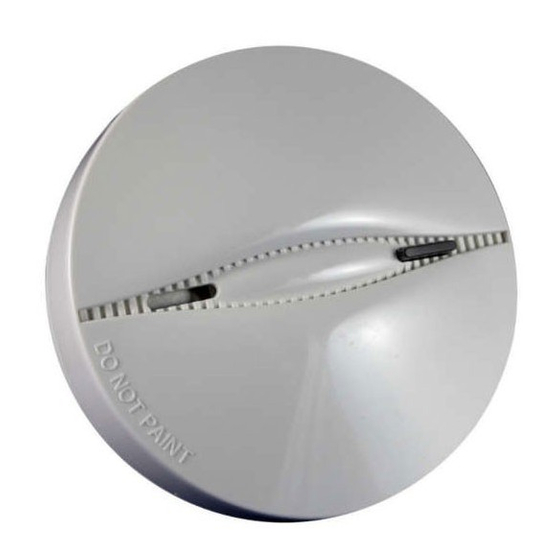
BUZZER
HOLE
Figure 1. General View (MCT-427)
Battery Life Expectancy: Battery life exceeds the minimum life
required by UL 268 and ULC 5531. Visonic warrantees the life of the
battery for 5 years.
Audible and Visual Low Battery Warning: Built-in horn beeps every
30 seconds simultaneously with red LED flashing (for up to 30 days
when the battery voltage drops).
Caution! Risk of explosion if battery is replaced by an incorrect type.
Dispose of used batteries according to the manufacturer's instructions.
Audible and Visual Degraded Chamber Sensitivity Warning: Built-
in horn beeps every 30 seconds in the middle of red LED flashing
intervals – indicates that the detector must be replaced.
Clean Warning Transmission: When the detector's chamber becomes
dirty, a Trouble signal that indicates the need to clean the detector is
sent to the control panel. A dirty chamber can cause the detector to
operate at high sensitivity. If this message persists after cleaning, you
may need to replace the detector.
Note: This transmission applies to the PowerMax+ (version F and higher)
and PowerMax Pro/Complete/Express control panels only.
PHYSICAL DATA
Operating Temperature: -10C to 50C (14F to 122F).
Relative Humidity: 10% to 85%
Dimensions: MCT-426 120 mm (4.7") x 58 mm (2.3")
MCT-427 120 mm (4.7") x 63 mm (2.5")
Weight (including battery): 165 g (5.8 oz)
Compliance with Standard:
MCT-426/427 Europe: (868.95, 433.92 and 869.2125 MHz):
EN54-7 (except for § 4.2), EN 14604. EN 54-5 Class A2-S (except for
§ 4.4), EN 60950, EN 300220, EN 301489, EN 50130-4.
USA: 315MHz (FCC) CFR47 Part 15
Canada: (315 MHz): RSS210
Designed to comply with:
MCT-426/427 USA (315MHz): UL 268
MCT-426/427 CANADA (315MHz): CAN/ULC 5531
BRACKET
1
Hold the
bracket with
one hand
TEST / MUTE
BUTTON
&
LEDS
DETECTOR
2
Rotate the
detector
anticlockwise
and pull it from
the bracket
1
Advertisement

Related Manuals for Visonic MCT-426


Summary of Contents for Visonic MCT-426
-
Page 1: Installation Instructions
2. SPECIFICATIONS Alarm Sound Level: 85 dB at 3 m (10 feet) Battery Life Expectancy: Battery life exceeds the minimum life required by UL 268 and ULC 5531. Visonic warrantees the life of the TRANSMITTER AND CODING battery for 5 years. -
Page 2: Audible And Visual Indications
(see fig. 1) until the built-in horn sounds, or press the tamper switch. Note: It is much easier to carry out this operation while holding the MCT-426 / MCT-427 in your hand, close to the control panel. D-302151 MCT-426, MCT-427 Installation Instructions... - Page 3 If some of your rooms have sloped, peaked, or gabled ceilings, try sleeper if the door is closed. to mount detectors 0.9 meter (3 feet) measured horizontally from the highest point of the ceiling as shown in Figure 9. D-302151 MCT-426, MCT-427 Installation Instructions...
- Page 4 However, due to their low transmitting power and may cause false alarms. Install smoke detectors at least 1.5 meters limited range (required by the regulatory authorities), there are (5 feet) from such lights. some limitations to be considered: D-302151 MCT-426, MCT-427 Installation Instructions...
-
Page 5: Battery Replacement
5.1 Battery Replacement B. Replace battery (see Figure 3a or Figure 3b according to the battery used). The MCT-426 and MCT-427 were designed to be as maintenance-free 5.2 Maintenance as possible. To keep the smoke detector in good working order, you It is necessary to maintain the detector frequently to ensure it working must test it weekly, as instructed in Para. -
Page 6: Statements Of Compliance
WARRANTY Visonic Limited (the “Manufacturer") warrants this product only (the "Product") to the original purchaser only (the However, if the Manufacturer is held liable, whether directly or indirectly, for any loss or damage arising under this “Purchaser”) against defective workmanship and materials under normal use of the Product for a period of twelve limited warranty, THE MANUFACTURER'S MAXIMUM LIABILITY (IF ANY) SHALL NOT IN ANY CASE (12) months from the date of shipment by the Manufacturer.