Table of Contents
Advertisement
Quick Links
Advertisement
Chapters
Table of Contents

Related Manuals for Triumph Adler CX 8036


Summary of Contents for Triumph Adler CX 8036
- Page 1 Instruction Handbook CX 8036 Large Format System...
- Page 2 This USER GUIDE contains functional and operational details of the Multifunction Printer. There are many sections in this guide for Basic Functions and Advanced Operations. Please see the TABLE OF CONTENTS. Please read this USER GUIDE carefully before using the Printer. Please keep this USER GUIDE for future reference.
- Page 3 Safety The following pages are very important in order to safely use this product. These notes are important in preventing harm to the operator or the operation of the printer. The following symbols are found throughout the USER GUIDE: WARNING This WARNING mark means that there is a possibility of death or serious injury if you ignore or do not follow the instructions.
- Page 4 WARNING Ground the product with a proper ground source or you may be electrically shocked. 1. The Power source should be: 120V +6% or -10%, 50/60Hz, 15A or higher 2. Use a circuit with a dedicated breaker. 3. Install the product as close to the wall outlet as possible. 4.
- Page 5 CAUTION Do not install the printer in a humidified room or a dusty room. Also, do not install the printer on an unstable floor as injuries may occur. 1. Unplug the printer before you move it. The power cord may be damaged and it may result in a fire or electric shock.
- Page 6 TABLE OF CONTENTS Section 1 Basic Printer Functions Section 2 Copy Mode Section 3 Scan Mode Section 4 Job Info Mode Section 5 Help – Configuration Section 6 Windows Drivers Section 7 AutoCAD Drivers Section 8 KIP Request Section 9 KIP PrintNet Section 10 Reporting Package - PRP Section 11 Connectivity...
-
Page 7: Table Of Contents
Section 1 Basic Printer Functions Page Before System Use 1- 1 1.1 Installation Requirements 1- 2 1.2 Prohibited Originals 1- 3 1.3 Key Features 1- 4 1.4 Specifications 1- 5 1.5 Exterior Views 1- 8 1.5.1 Front View 1- 8 1.5.3 Rear View 1- 9 1.5.4 Operator Panel... -
Page 8: Installation Requirements
1. 1 Installation Requirements The following conditions are required for the installation of the equipment. 1. Power source should be rated as: 120V +6% or -10%, 50/60Hz, 15A or higher 2. The equipment must be on a dedicated circuit. 3. The outlet must be near the equipment and easily accessible. 1. -
Page 9: Prohibited Originals
1. 2 Prohibited Originals To duplicate or copy any type of document is not permitted! It may be illegal if you possess copies of certain types of documents. We recommend you investigate if you have the legal right to copy / scan a document prior to performing these functions. -
Page 10: Key Features
1. 3 Key Features The system is a single footprint Multi-Function Printer which can copy, scan and print. Advanced drivers and comprehensive print utilities make the system an advanced, easy to use system. (some functions may be optional) The scan and print speeds are up to 60mm/sec or up to 4 landscape “D” prints/minute. KIP HDP technology generates no waste toner. -
Page 11: Specifications
1. 4 Specifications General Subject Specification Model CX8036 Configuration Console Maximum power 1500W (Including Scanner & IPS) consumption Acoustic noise Idling Max. 52db Printing Max. 60db Impulse sound Max. 65db Ozone Max. 0.1ppm (Measurement method under UL Standard) Dimensions 1240mm (W) x 600mm (D) x 1100mm (H) or 49”... - Page 12 Printer Subject Specification Model CX8036 Configuration Console – Single Footprint Printing method LED Array Electro-Photography Photoreceptor Organic Photoconductive Drum Print speed 60mm per second (Metric) 2 A0 / minute (Inch) 2 E or 4 D Landscape / minute Print head LED Array –...
- Page 13 Scanner Subject Specification Scanning method Contact Image Sensor (CIS) (5 – A4) Light source Setting of original Face up Starting point of scan Center Scan width Max. : 914.4mm or 36” Min. : 275.0mm or 11” Transportable original Max. : 932.2mm or 36.7” width Min.
-
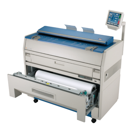
Page 14: Front View
1. 5 Exterior Views 1. 5. 1 Front view Name Function Main Switch Turns on / off. Original Guides Assists the user to feed originals into the scanner. User Interface Operation Panel, with many user operations. Emergency Stop Button Press this button when you would like to stop copying or scanning in an emergency situation. -
Page 15: Rear View
1. 5. 2 Rear view Name Function Exit Cover Open the Exit Cover when you remove the paper mis-fed inside of the Fuser Unit. LAN Port Connect the LAN Cable here to connect the system to the network. (Do not connect a telephone line.) Dehumidify Heater Switch Turn on the Dehumidify Heater with this switch when you (Option) - Page 16 1. 5. 3 Operator Panel – User Interface Basic Screens Copy Mode Name Function Mode Selects the “Mode” of the system. (Copy Mode for this screen shown) Media Displays Media type and quantity installed. Includes Cut Sheet Functions and Media Selection Original Type User Selects the type of original to copy.
-
Page 17: Scan Mode
Scan Mode Name Function Mode Selects the “Mode” of the system. (Scan Mode for this screen shown) Original Size Use automatic settings or manually set width, length and rotation of the images. Original Type User Selects the type of original to copy. Also select Eng/Arch Mode selected here. - Page 18 Job Info Screen Name Function Mode Selects the “Mode” of the system. (Job Mode for this screen shown) User Name – Job # Display the User and any user info of the job ID. A job can be selected for other functions noted below. Status Shows the current status of a job and media selection.
-
Page 19: Information / Help Screen
Information / Help Screen Name Function Mode Selects the “Mode” of the system. (Info/Help Mode for this screen shown) Meter – Versions Display the current meter counts as well as all Software/Firmware versions, IPS number, Host Name/IP Contact Shows the contact information for the Service and Supplies provider. - Page 20 1. 6 Options - Accessories Please contact your Authorized Reseller for the following options available: 1) Network Printing Adds the functions of network printing (TCP/IP) from Windows and CAD applications. Includes Windows/PS drivers, AutoDesk Drivers, “Request” job submission utility and “KIP PrintNet” for web based submissions.
-
Page 21: Turning On
2. 1 Turning on 1. Ensure the system is plugged into a dedicated wall outlet. WARNING (1) Do not handle the Power Plug with wet hands, or you may receive an electrical shock. (2) Make sure to ground the machine for your safety. (3) Do not plug the printer into a multi-plug connector in which other devices are plugged into. -
Page 22: Turning Off
2. 2 Turning off 1. There is a Power Switch on the right side of system. Switch to the “ O ” position to turn off the system. Power Switch 2. 3 Roll Media Replacement 1. Open the Roll Deck (1). Remove the Spool (2) with the roll core from the Roll Deck. - Page 23 3. If so required, loosen the knob (4), slide the position of Paper Guide (5) according to the width of media to be installed, and then secure the Paper Guide by tightening the knob. NOTE There are Size Guides (6) on the Spool. The Paper Guide is provided with a triangle mark (7), place the Paper Guide so that the triangle aligns with the line of Size Guide.
- Page 24 5. Place the Spool with new roll into the Roll Deck. 6. Insert the leading edge of the media under the Guide Plate (8) until the edge touches the feeding roller. Then rotate the Feeding Handle (9) clockwise so that the feeding rollers catch the roll paper.
- Page 25 8. Slide the Cutter Handle (12) fully from one side to another side to cut the leading edge. Remove the cut portion and discard. 10. Close the Roll Deck. 11. On the Operator Panel, a screen will automatically appear after the deck is closed to define the media width and type.
-
Page 26: Toner Installation
2. 4 Toner Installation When toner installation is required, the Operator Panel will display a “Toner Required” screen (in the “Copy” and “Job Info” Screens) To replace the toner cartridge, please follow these steps: Please note that the replacement procedure can also be displayed on the Operator Panel for easier access, by pressing “User Guide : Changing Toner”... - Page 27 3. Pressing down on the Cartridge Lock Lever (3), rotate the body of cartridge (4) in the arrow direction several revolutions until it stops turning. The cartridge is resealed by this procedure! NOTE If you remove the Toner Cartridge without resealing the toner outlet (5) the toner will drop from the toner outlet and it will scatter into the machine or onto the floor!
- Page 28 6. Locate the pin (6) of the left side of cartridge. While pressing down the Cartridge Lock Lever (3), fit the pin to the groove (7) 7. Rotate the body of the cartridge (4) to the arrow’s direction, several revolutions to open the toner outlet.
- Page 29 8. Close the Toner Cover. 9. Press “OK” on the Operator Panel to continue copying or printing. 1-23 Section 1 Basic Printer Functions...
-
Page 30: Cut Sheet Media Placement
2. 5 Cut Sheet Media Placement 1. Select Cut Sheet Bypass Button on the Operator Panel. (Copy Mode) 2. Select the size of the sheet, and the media type (not shown) 3. Or use “Custom” to select a width. 1-24 Section 1 Basic Printer Functions... - Page 31 4. Select a standard length or use a “Custom Length”. 5. Confirm the cut sheet size by pressing enter. 6. Open the Cut Sheet Feeder (1). 1-25 Section 1 Basic Printer Functions...
-
Page 32: Emergency Stop Of A Copy Or Scan
6. There are size markings on the table. Insert the cut sheet paper on the table along with the associated size mark, and then insert it into the Feeder referencing the size marks. When the paper is inserted far enough, the machine automatically sets the paper at the proper position. -
Page 33: Dehumidifying The Roll Media
2. 7 Dehumidifying the Roll Media If the printer is located in an environment where the humidity may effect the image quality, please turn on the dehumidifiers. 1. Select Switch to “ I “ position Dehumidifier switch NOTE Dehumidifiers are an option for the system. Please contact you local dealer for details. -
Page 34: Operational Errors
3. 1 Operational Errors 3. 1. 1 Paper mis-feed Errors In case of a paper jam, a message will be displayed on the Operator Panel as well as the Technical LCD. One of the following messages will be displayed if an error does occur. Roll Deck / Feeding Jam Cut Sheet / Manual Jam Internal Jam Resist Jam... - Page 35 NOTE In case of Roll 2, rotate the Feeding Knob of Roll 2 (4). 3. When the feeding rollers catch the paper, move the Lever (5) forward and rotate the Feeding Knob (3) until the leading edge comes out from the guides. Leading edge of roll paper 4.
- Page 36 3. 1. 1. 2 Cut Sheet / Manual Paper Jam 1. Carefully remove the paper by pulling as noted. 3. 1. 1. 3 Resist Jam / Internal Jam 1. Pull up the Engine Levers (1) to open the printer. 2. Remove any mi-fed paper. 1-30 Section 1 Basic Printer Functions...
-
Page 37: Fuser Jam
3. 1. 1. 4 Fuser Jam 1. Open the Fuser Cover (1). 2. Remove the jam paper, by carefully pulling out the back. WARNING There are extremely hot parts inside of the Heater Area. Do not touch any parts in the Heater Unit, or you will be burnt! Also note that the paper may be very hot as well. -
Page 38: Deck Is Open
3. 1. 2 Others 3. 1. 2. 1 Deck is open This message is displayed when the Roll Deck is opened. Reopen and then close it firmly. Roll Deck 3. 1. 2. 2 Optional Finisher Jam The media is mis-fed in the optional finishing device such as a Stacker or Folder. Remove the mis-fed paper referencing the User Guide of optional device. -
Page 39: Toner Empty
3. 1. 2. 5 Toner Empty This message is indicated when the Toner Cartridge is empty with the toner. Replace the Toner Cartridge referencing [2. 4 Replacement of Toner Cartridge] Toner Cartridge 3. 1. 2. 6 Paper Empty This message is indicated when the roll paper is empty. Roll paper Replace media referencing [2. -
Page 40: Call Service Errors
3. 2 Call Service Errors If the machine has the fatal error you will note one of the following Error Codes on the Technical LCD panel. It is impossible for the user to resolve these errors. PLEASE CONTACT YOUR AUTHERIZED SERVICE PERSONNEL TO RESOLVE THESE ERRORS. - Page 41 Section 2 Copy Mode 1. 0 Copy Mode..........................3 Main Screen - General ....................3 Simple Copying ....................... 4 1.2.1 Select Copy Mode ....................... 4 1.2.2 Select Size Mode ......................4 1.2.3 Select Original Image Type ..................5 1.2.4 Copy Count ........................5 1.2.5 Media ..........................
- Page 42 1.10.4 Auto Zoom ......................25 1.10.5 Clear ........................26 1.11 Start ..........................26 1.12 View Last........................26 1.13 Recall Job ........................26 1.14 Stop / Reset ........................26 1.15 Interrupt ........................26 1.16 Rescan ........................... 27 1.17 Log Off ........................... 27 Section 2 Copy Mode...
-
Page 43: Copy Mode
1. 0 Copy Mode 1.1 Main Screen - General Name Function Mode Selects the “Mode” of the system. (Copy Mode for this screen shown) Media Displays Media type and quantity installed. Includes Cut Sheet Functions and Media Selection Original Type User Selects the type of original to copy. -
Page 44: Simple Copying
1.2 Simple Copying To copy, please follow these basic steps. The following chapters have details on adjustments and parameters that the user can change to modify the copies as required. 1.2.1 Select Copy Mode On the lower region of the Operator Panel select “COPY”. 1.2.2 Select Size Mode Select whether the document is an engineering or architectural size document. -
Page 45: Select Original Image Type
1.2.3 Select Original Image Type Set the original image type you will copy. The selections are: Line - used for simple line documents Line / Photo - used for a combination of lines & photos documents Greyscale - used for a combination of lines & areas of shade (CAD) originals Photo - used for photographic originals This will allow automatic image quality adjustments for the scan. -
Page 46: Media
1.2.5 Media Selects automatic (for best possible fit) or manual roll selection. 1.2.6 Length Select Auto for automatic cut length (to the length of the original) or Standard Cut for a manual length. (a number pad will request the desired length to be entered) Section 2 Copy Mode... -
Page 47: Size
1.2.7 Size Select a) AutoZoom to automatically zoom to the width of paper or b) press the arrow keys to scroll through presets ratios or c) press on the Zoom number to enter a ratio on the key pad 1.2.8 Insert Original Using the guides on the feed table, center the original face up and insert the document. -
Page 48: Operation Details
2. 0 Operation Details 1.3 Main Screen The main Copy screen is selected with the Copy Button. It contains all user functions for copying. The following pages details the functions and settings of each button and sub screens that can be used to adjust the copy mode parameters to achieve the required result. -
Page 49: Original Type
1.4.2 Original Type There is a selection of four different predetermined original types. The selections are: a) Line - used for simple line documents b) Line / Photo - used for a combination of lines & photos documents c) Greyscale - used for a combination of lines &... -
Page 50: Threshold
1.5.2 Threshold To override the “Automatic” setting, “Threshold” can be adjusted. Deselect “Auto” to enable “Threshold”. When the arrows are pressed the threshold will be set to a desired level. This will suppress or enhance the lines and images on the original. -
Page 51: Arrows - Count Increase / Decrease
1.6.1 Arrows - Count Increase / Decrease Use the arrows to increase or decrease the total numbers of copies desired by one with each press of the button. In this example the arrow was press seven times to reach “8 copies”. 1.6.2 Number Pad - Count Increase / Decrease Press the ”number of copies”... -
Page 52: Clear
c) Copying will not commence until the set is closed. To close a set, press the start button. The set with the total number of copies will be printed. An example of Set Copy: 3 originals with 3 sets or copies Originals Copies 1.6.4 Clear... -
Page 53: Advanced Settings
1.7 Advanced Settings The Advanced Setting button contains the additional parameters on a sub screen: a) Mirror b) Invert c) Fold (if optional device connected) d) Stamp (Water Mark) e) Lead Edge Adjustment f) Trail Edge Adjustment When any of the adjustments / selections are selected, the selections will now be displayed on the main Copy screen 1.7.1 Mirror Select this button to “mirror”... -
Page 54: Stamp
b) The fold selected will be displayed in the button. c) Select OK NOTE The list of “Folds” are loaded into Copy Mode by the system administrator or key operator. They can not be altered or modified in any manner on the system Operator Panel. -
Page 55: Leading Edge Adjustment
NOTE The list of “Stamps” are loaded into Copy Mode by the system administrator or key operator. They can not be altered or modified in any manner on the system Operator Panel. Please contact these persons for any additional stamps that may be required. Please see “KIP Request”... -
Page 56: Trailing Edge Adjustment
1.7.6 Trailing Edge Adjustment The trailing edge of each copy can be altered. ( +/- 4” ) c) additional void area can be placed on the bottom of a copy or d) image can be removed (such as a binding strip or a file hanger) Trail edge + Trail Edge - Image... -
Page 57: Auto
1.8.1 Auto This default setting allows the copier to automatically select the best media roll width to print the image onto. It selects the roll noting the amount of image area to prevent surplus media consumption. (applies to the option - two roll model) Example: 22”... -
Page 58: Enabling Cutsheet
1.8.3 Enabling Cutsheet The system is equipped with a cut sheet feeder that can be enabled in the configuration menu of the user interface. This can be accomplished by following these steps 1. Select the (?) button in the bottom left corner of the user interface. -
Page 59: Copying To Multiple Cutsheets
c) Open the Cut Sheet Feeder (1) and WAIT until prompted by the UI to insert the Cut Sheet media. d) There are size markings on the table. Line up the original cut sheet on the feed table with the associated size marks. When the paper is inserted far enough, the machine automatically sets the paper at the proper position. -
Page 60: Media Remaining
1.8.6 Media Remaining The installed roll information is displayed in the button of the particular roll deck. Beside each deck is a volume of media that currently is left on the roll of media. Indicators will display full, 3/4 ,1/2, 1/4 or empty 1.8.7 Installing Roll Media When media is replaced or installed, a screen will automatically appear. -
Page 61: Length
1.9 Length Two methods determine the length of the copy. These two methods are Auto (may also be known as Syncro Cut or Automatic Cut ) and Standard Cut. 1.9.1 Auto This mode allows the media length to be determined by the original length. - Page 62 - If a roll is already selected in Media, then the following screen appears now only requesting the length. b) Once the roll is determined (if so required) the length can now be set. - Standard Length - Auto Length - Custom Length c) Standard Length –...
-
Page 63: Size - Zoom
e) Custom Length – set the custom length in the key pad and press enter f) the cut length will now be displayed in the main Copy screen in the Standard Cut button. 1.10 Size – Zoom Image size / Zoom can be altered in this region of the operator panel. This includes automatic zooming, predetermined percentages, or ratio calculations to page size, and simply percentage increments. -
Page 64: Percentage Key Pad
The pre-programmed percentages are: 50 - 66.7 - 70.7 - 100 - 141 - 150 - 200 1.10.2 Percentage Key Pad To enter a percentage directly into the system, a) press on the Percentage value displayed (the number is a button). b) This will show a keypad to enter the value. -
Page 65: Auto Zoom
b) Select Standard button. c) Select the original page size by pressing onto the original page size button. d) Please note either Engineering or Architectural mode can be utilized by pressing on the button below the original page size. e) Select the desired Copy page size. Again please note either Engineering or Architectural mode can be utilized. -
Page 66: Start
b) If a roll is not selected (Auto is currently selected), roll selection is requested prior to the function of Auto Zoom. If cut sheet is used then it will use the values set in the Cut Sheet button in Media. 1.10.5 Clear To reset the percentage value to default, press the “C”... -
Page 67: Rescan
1.16 Rescan This button only appears when “Set Copy” mode in enabled. It allows a user to rescan an original in a set as required. This may be due to skew or incorrect image quality settings of the previous scan. 1.17 Log Off This button only appears when “Accounting”... - Page 68 2-28 Section 2 Copy Mode...
- Page 69 Section 3 Scan Mode 1. 0 Scan Mode ..........................2 Main Screen ........................2 Simple Scanning ......................3 1.2.1 Select Scan Mode....................3 1.2.2 Select Size Mode ..................... 3 1.2.3 Select Original Image Type ..................4 1.2.4 Select Format......................4 1.2.5 Select Destination ....................
-
Page 70: Scan Mode
1. 0 Scan Mode 1.1 Main Screen Name Function Mode Selects the “Mode” of the system. (Scan Mode for this screen shown) Original Size Use automatic settings or manually set width, length and rotation of the images. Original Type User Selects the type of original to scan. Also select either Eng/Arch Mode here. -
Page 71: Simple Scanning
1.2 Simple Scanning To scan to file please follow these basic steps. The following chapters have details on adjustments and parameters that the user can change to modify the scans. 1.2.1 Select Scan Mode On the lower region of the Operator Panel select “SCAN”. 1.2.2 Select Size Mode Select whether your document is an engineering or architectural size document. -
Page 72: Select Original Image Type
1.2.3 Select Original Image Type Set which Original Image type you will scan. The selections are: Line - used for simple line documents Line / Photo - used for a combination of lines & photos documents Greyscale - used for a combination of lines & areas of shade (CAD) originals Photo - used for photographic originals This will allow automatic image quality adjustments for the scan. -
Page 73: Select Destination
1.2.5 Select Destination Select the location to where the file will be saved. Use the “Page Arrows” as required to view other choices currently available. NOTE The choice of destinations are predetermined by the system administrator or key operator. Please contact these persons for any additional locations that you may require. -
Page 74: Operation Details
2. 0 Operation Details 2.1 Main Screen The main SCAN screen is selected with the Scan Button. It contains all user functions for scanning to file. The following pages details the functions and settings of each button and sub screens that can be used to adjust the scan parameters to achieve the required result. -
Page 75: Original Type
This will allow the automatic width detection system to determine the image width when an original is placed in the scanner. (Eng) Engineering widths = 34, 22, 17, 11, and 8.5 inches (Arch) Architecture widths = 36, 30, 24, 18, 12, and 9 inches 2.2.2 Original Type There is a selection of four different predetermined original types. -
Page 76: Manual Size
2.3.2 Manual Size To override the “Automatic” settings, “Manual” can be selected. When this button is pressed, sub screens will appear: Select the size of the sheet Or use “Custom” to select a width. c) Set a standard size width. Section 3 Scan Mode... -
Page 77: Hard Drive Space Monitor
d) Select a standard size length or e) a custom length with the key pad. f) press, “Reset” to begin again, “Enter” to accept the settings or Cancel” to cancel “Manual” image size. 2.3.3 Hard Drive Space Monitor Located on the main screen of the system scan menu, the hard drive monitor provides a real- time display of remaining disk space. -
Page 78: Rotation
The main Scan screen will now display the custom or manual size settings for the next image. 2.3.4 Rotation The file can be saved rotated, differ than the actual feed direction. This can be used to reduce the scan time on certain orientation of originals, when they are archived. Press the “Rotation”... -
Page 79: Density
2.4.2 Density To override the “Automatic” setting, “Density” can be adjusted. Deselect “Auto” to enable “Density”. When the arrows are pressed the background density will be set to a desired level. This will suppress or enhance the background of the original. -
Page 80: Format
2.6 Format Press the “Format” button to scroll through the file formats available. TIF-G4 - tif format Group 4 level compressed - format compressed CAL-G4 - Cals Group 4 level - PDF Level 3 Select the file type required to save the image into this format. Cals 2.7 Advanced Settings The Advanced Setting button contains the additional parameters on a sub screen:... -
Page 81: Mirror
Make any of the required adjustments / selections and press “OK” to accept. The selections will now be displayed on the main Scan screen 2.7.1 Mirror Select this button to “mirror” a scan. This can be utilized on originals that may have the actual image on the reverse side such as older “sepia”... -
Page 82: Leading Edge Adjustment
b) The Stamp button will now display the stamp selected. NOTE The list of “Stamps” are loaded into Scan Mode by the system administrator or key operator. They can not be altered or modified in any manner on the Operator Panel. Please contact these persons for any additional stamps that may be required. -
Page 83: Trailing Edge Adjustment
2.7.5 Trailing Edge Adjustment The trailing edge of a scan can be altered. ( +/- 4” ) c) additional void area can be placed on the bottom of a scan or d) image can be removed (such as a binding strip or a file hanger) Trail edge + Trail Edge - Image... -
Page 84: Destination
2.8 Destination This region of the Scan screen allow the user to select where the files will be placed. 2.8.1 Selecting a Destination a) Use the arrow keys to scroll through the list as needed. b) Select the location by pressing on it 2.8.2 Setting a New Destination a) Press the Destination Button... -
Page 85: Removing A Destination
c) Enter the new location using standard protocols of networking for scans to the: IPS Mailbox Set the a simple name for the location Examples: Dsmith B_Project Team_XYZ Michele Access to these folders and the scanned images is preformed from the KIP Request application. -
Page 86: Start
c) and then press “Remove” 2.9 Start No function at this time in Scan Mode. All scans in Scan Mode are “Auto Start”. 2.10 Reset / Stop This button has two functions. 1) Press the Stop button on the Operator Panel to stop the current scan. After the original has been stopped, press the Stop button again to eject the document from the scanner or open the scanner lid to remove the original. - Page 87 Section 4 Job Info Screen Page 1. 0 Job Info Screen 4- 2 1.1 Main Screen – Summary 4- 2 2. 0 Operation Details 4- 3 2.1 Job List - Main Screen 4- 3 2.2 User Name 4- 4 2.3 Job – Number 4- 4 2.4 Status 4- 4...
- Page 88 1. 0 Job Info Screen 1.1 Main Screen Name Function Mode Selects the “Mode” of the system. (Job Mode for this screen shown) User Name – Job # Display the User and any user info of the job ID. A job can be selected for other functions noted below.
- Page 89 2. 0 Operation Details The Job Info screen is used to view or manage the current copy or prints jobs. 2.1 Job List - Main Screen All jobs which are currently printing or are waiting to print are displayed in this area. You may make a job large for viewing (or for other functions described further in this manual) by selecting the job from the list Section 4...
-
Page 90: User Name
User Name Displays the “Name” or the “owner” of the job. This information is known from a field from within a) KIP Request b) KIP Windows Driver c) KIP AutoCAD Driver d) or from the Accounting Fields as a copier when accounted is enabled Please see respective User Guides for detailed information An example screen from Request:... - Page 91 Type Displays the source of the job. Jobs can be sent from the network or as a copier. If from the network the following symbol is displayed: If from a copy job the following symbol is displayed: Total Displays the number of prints. This includes a) the quantity in each job b) the amount remaining , when a job is printing.
- Page 92 b) Press the “To Top” button c) The list will be updated with urgent job to be printed next. Pause To pause all print jobs ( to replace paper or another task that may require the printer to pause) press the pause button. Delete To remove a job from the Job list: a) Select the job to remove...
- Page 93 b) Press the Delete button c) The job will be removed from the list. 2.10 Page Scroll Arrows may appear in the lower right corner of the screen to scroll through the pages of jobs. Please note that the total number of pages will also be displayed as well as the current page.
- Page 94 Section 4 Job Info Screen...
- Page 95 Section 5 Help-Configuration Screen 1.0 Help – Configuration Screen................... 2 1.1 Overview ....................... 2 “?” Screen – General ..................3 2.0 Main Screen - Details ....................4 2.1 Information Region....................4 2.1.1 Meter A ......................4 2.1.2 Total Run ......................5 2.1.3 Meter B......................
-
Page 96: Help - Configuration Screen
1.0 Help – Configuration Screen 1.1 Overview The CX 8036 has the ability to display information about the system and allow detailed configuration or settings for Copy and Scan modes. It also has visual user guides which can also assist the user to perform the functions of the system. -
Page 97: Screen - General
1.2 “?” Screen – General No. Name Function Mode Selects the “Mode” of the system. (Help Mode shown) Information Region Displays meter counts and version number of the system. Support / Supplies Displays the contact information for technical support and printer supplies. User Guide Enters the Graphical Users Guides. -
Page 98: Main Screen - Details
2.0 Main Screen - Details 2.1 Information Region This area of the Screen includes meter counts and software versions 2.1.1 Meter A Displays the total number of units run on the printer. This counter should match the hard counter on the right mid- front section on the printer. This unit is in square feet in North America and in Square Meters in all other countries. -
Page 99: Total Run
2.1.2 Total Run This meter counts the total number of linear meters run on the printer in all countries. One count = one linear meter NOTE The units of this counter are from the internal processor of the printer and cannot be “reset”... -
Page 100: Machine Serial Number
2.1.9 Machine Serial Number Displays the hardware serial number. This is also located on the lower rear of the printer. NOTE If this serial number differs from the “hard coded” number on the lower rear of the printer contact your local service company! The hard code serial number is to be taken as correct in case of any discrepancies 2.2 Supplier / Technical Support The region is supplies the contact information for supplies and... -
Page 101: User Guides
3.0 User Guides Press the User Guides button to gain access to the User Guides. The User guides cover the most basic functions of the system operations including media / toner replacement. For comprehensive details please consult this User Manual. a) select the function assistance is required with... -
Page 102: Configuration
4.0 Configuration 4.1 Inch or Metric Units Set the system from “Inch Mode” to “Metric Mode” by pressing the Inch or Metric button. This will effect the entire System, including Scan, Print and Copy. Please note that the printer must be set to the correct size mode for proper print function. -
Page 103: Reset Timer
User Configuration Service Configuration a) Set the timers by pressing on the hour, minutes and AM/PM as needed. b) If the printer is required during the “sleep” period, it will simply awake, produce the prints and then “fall asleep“ again, 15 minutes later. -
Page 104: Default Mode
4.7 Default Mode Sets which Screen will be the default Mode, Scan or Copy Mode dependent of the installation environment requirements. 4.8 Default Original Size – STF Either Engineering or Architectural sizes can be set as the default width detection in Scan Mode. This will allow automatic width detection of either one of the two formats. -
Page 105: Test Pattern
4.11 Test pattern A variety of test patterns may be printed from the operator panel on an on-demand basis. The following four predefined test patterns are available to assist in pen table selection and overall quality verification. 36” x 60” tif – Used to test long printing and calibrate scan/copy operations 17”... -
Page 106: Cut Sheet
4.17 Cut Sheet Enables / Disables the cut sheet function, which may not be required in certain installation. 4.18 Interrupt Allows the Interrupt button to function in the Copy Mode. Enabled = allows the user to pause all network print jobs to allow copies to be printed first Disabled = all copy jobs will be placed in the queue as the order they are received within any network print jobs. -
Page 107: Appendix
Appendix 5.0 Print Queue Management Configuration Menu The first selection displayed underneath the print queue, the configuration button will call up a dialog box with five selections, which are: Set monitor paths Allows the user to set up to different paths for the Powerprint Unattend software... - Page 108 Configure Monitored Directory Any files (raster, vector) or the Job ticket can be sent to C:\Monpath1\Request folder. Individual files sent to this folder will use the data folder that is user configurable. ‘C:\Monpath1\Request’ is a fixed path and CANNOT be changed. The ‘Configure’...
- Page 109 Creating Custom LPR Paths to be used with Unattend 1. Set up new printer object on KIP IPS a. Add a printer wizard b. Select local Printer c. Use the KIP0 Port (already installed) 5-15 Section 5 Help-Configuration...
- Page 110 d. Select Printer Driver from List e. Choose Keep existing Driver 5-16 Section 5 Help-Configuration...
- Page 111 f. Setup Queue name (all Caps in English) g. It is not necessary to Share driver 5-17 Section 5 Help-Configuration...
- Page 112 h. It is not necessary to print test page 2. Configure new queue (Printer Object) in the KIP Unattend software a. Launch the Unattend Software on the IPS Controller b. Select Configuration 5-18 Section 5 Help-Configuration...
- Page 113 c. Select Set Monitor Paths d. Select the Right Arrow Button to Change the path to the Next available path. e. Set the new LPD Directory Path f. Set the new LPD Printer Name 5-19 Section 5 Help-Configuration...
- Page 114 3. Configure the LPD Queue Directory (instructions for the Queue) a. Choose the settings or instructions that you desire for this Queue. 4. Save Changes (click Ok) 5. Send Test files with LPR command a. LPR –SK3K -PVELLUM File.plt (in this example “VELLUM” is the queue name you created and “File,plt”...
- Page 115 Miscellaneous Setup Allows the user to set up custom configurations of media defaults, copy density, password protection, etc. Variables within the miscellaneous configuration include: English / Metric Allows the user to set the controller to read either English or Metric standards of measurement.
- Page 116 Print Configs Allows the user to print all configuration files (.INI files) with the touch of a button. sleep when there’s no apparent printing that’s needed, or can set up time for the printer to wake up. By default, the printer will start warming back up anytime a Job / file arrives at a monitored path for printing.
- Page 117 Section 6 Windows Driver Page 1. 0 Introduction 6- 2 1.1 Introduction 6- 2 1.2 Option Screen – Overview 6- 3 2. 0 Function / Feature Details 6- 4 2.1 Output Format 6- 5 2.2 Orientation 6- 5 2.3 Scaling 6- 5 2.4 Copies 6- 5...
- Page 118 1. 0 Introduction 1.1 Introduction The KIP Unified Windows Printer Driver (KUWPD) allows windows printing from Microsoft Windows NT4 / 2000 / XP Operating systems as well as 2003 Server based applications. The KIP Unified Windows Printer Driver is available for download from your local website and is also supplied with your Printer on the software CD.
- Page 119 1.2 Option Screen - Overview Commencing from the top of the layout above, these are the main features on the KUWPD Name Feature / Function Output Format Selects the type of “language” for driver output Orientation Rotation of the page Scaling Allows scaling of an image to the page size if not supported in the application.
-
Page 120: Output Format
2. 0 Function Details 2.1 Output Format The KUWPD improves support for many Windows applications by providing dual output printer language capabilities. Selecting the Output Format in “Printing Preferences” or “Document Defaults” (NT4), before entering an application will select the proper output method. -
Page 121: Media Type
2.2 Orientation There are two types or Orientation in the driver: Landscape and Portrait. Examples: Landscape Portrait Selection of the orientation should take into account the design or layout from within the application. If an incorrect orientation is selected the page size can be “rotated” incorrectly and image may be lost in the final printed output. - Page 122 This is a feature that is very important in wide format printing from CAD applications and MS Excel. This is a feature that is required in CAD applications where the image size may vary from one image to the next such as: 36” x 60” for the first document then 24” x 80” for the next.
- Page 123 2.10 Header To easily recognize printed documents, text can be placed on the top of bottom of the print. The text header includes all the “Management” information as well as the file name. Text here Text here 2.11 Folder If an optional folding device is installed onto the printer, select fold to allow the printer to determine which fold table to apply to the document.
- Page 124 Installation 3.1 Prerequisites Requirements at the Network Server or User Workstations a) The KIP Unified Windows Printer Driver (KUWPD) allows windows printing from Microsoft Windows NT4 / 2000 / XP Operating systems as well as 2003 Server based applications. (Windows 9x is not supported) b) Please ensure that your applications are as up-to-date as possible, in terms of version, available service packs, and hot fixes.
- Page 125 3.2 Installation Process - Automatic KIP Unified Windows Printer Driver (KUWPD) can be installed on Microsoft Windows NT4, 2000, XP, 2003 platforms (Windows 9x platforms not supported) by using the provided printman.exe utility or by manually adding a port monitor (monitor.inf) and printer driver (plotter.inf).
- Page 126 e) Do not change Port Name f) Choose Server/Workstation from Installation Location g) Do not change Destination Directory h) Provide the IP address OR hostname of your KIP printer for Controller Name / IP Address. It is important to add EITHER the hostname OR the IP address. Do not add both.
- Page 127 3.3 Installation Process - Manual The printman.exe utility is designed to automate the installation of the KIP Port Monitor (KIP0) and the KIP Unified Windows Printer Driver (KUWPD). It is possible to install both components manually. Manual installation techniques may be necessary to satisfy IT and/or corporate requirements.
- Page 128 d) Select Add Port. Printer Ports dialog is displayed. Select New Port Type. e) Browse to the appropriate operating system folder from the KUWPD distribution, and select monitor.inf. Select OK. KIP Port Monitor is added to Available Port Types. f) Select KIP Port Monitor and click New Port. g) Configure KIP Port: f) Do not change Port Name unless required* * For multiple KIP printers, create an additional KIP Port per printer named KIP1,...
- Page 129 3.4 LPR / LPD Port The Microsoft provided TCP/IP Port Monitor can be used as an LPR/LPD type of port instead of the KIP0 port. During configuration of TCP/IP Port Monitor, LPR must be used, with LPR Byte Counting enabled. LPR/LPD implementation requires a Queue Name to be defined.
- Page 130 c) From the Control Panel, Printers menu select “Add Printer”. When the Printer Wizard dialog is displayed* select Local printer attached to this computer. Click Next * Microsoft Windows NT4 screens will vary slightly from those shown d) Select Using the Following Port, and assign KIP0, or use KIP1, KIP2 depending on the installation.
- Page 131 e) Install Printer Software dialog is displayed. Click Have Disk. f) Depending on your operating system, locate the appropriate folder that contains the plotter.inf for your system platform. KUWPD / WINNT4 = Microsoft Windows NT 4 Workstation / Server KUWPD / WIN2000 = Microsoft Windows 2000 Workstation / Server KUWPD / WINXP = Microsoft Windows XP, Microsoft Windows 2003 Server g) Select the appropriate Printer from the list displayed.
- Page 132 h) Provide a Printer Name when prompted. Select Next. i) Assign a shared name (if applicable)*. Select Next * If replacing a previously shared driver, it is possible to use the same share name. 6-16 Section 6 Windows Driver...
- Page 133 j) Determine if you would like to print a Test Page when prompted. Select Next. k) Completing the Add Printer Wizard dialog is displayed. Click Finish. Printer Driver is added to system. l) Installed printer can now be accessed from the Microsoft Printer Control Panel* * If printer is not seen, press F5 to refresh the printer list 6-17 Section 6...
- Page 134 m) Right-Click printer and select Printing Preferences*. User Interface is displayed. * For Microsoft Windows NT4, select Document Defaults n) The following settings will determine the initial defaults for the printer driver. These defaults will be acquired by client workstations connecting to the shared printer driver.
- Page 135 Appendix 4.1 File Structure Overview When the printer driver is unzipped and copied to the Hard Disk of the system it will be installed on, the directory and file structure is as follows: C:\KUWPD C:\KUWPD\WINNT4 C:\KUWPD\WIN2000 C:\KUWPD\WINXP KUWPD • Printman.exe- Installation utility for Microsoft Windows NT4 / 2000 / XP / 2003. Provides a GUI for Printer Port Monitor and Printer Driver installation.
- Page 136 WINXP • Kaw2kppm.dll- Printer Port Monitor for Microsoft Windows 2000 / XP / 2003 • Kipgs24.ppd- Postscript Printer Definition File • Kipgs400.ppd- Postscript Printer Definition File • Kipgs600.ppd- Postscript Printer Definition File • Kipgs1020.ppd- Postscript Printer Definition File • Kuwxppd.dll- Printer Driver DLL for Microsoft Windows 2000 / XP / 2003 •...
-
Page 137: Printing Hints
4.2 Printing Hints • Issue: Adobe Acrobat 6.X products, when printing with KIP GL output language and large size (E-Size or larger) documents has potential to miss or clip off data prematurely. Solution: Adobe Acrobat 7.X products correct this issue. Acrobat 6.x requires the use of KIP Script output to solve this issue (choose KIP Script in the drivers Printing Preferences prior to opening Acrobat 6) •... - Page 138 6-22 Section 6 Windows Driver...
- Page 139 Section 7 KIP AutoCAD HDI Driver Page Overview and Features 7- 2 Connection 7- 4 2.1 Options 7- 4 2.2 KIP Request Link – Advanced Features 7- 4 Installation 7- 5 Configuration 7- 8 4.1 Media 7- 8 4.2 Graphics 7- 9 4.3 Custom Properties 7- 9...
- Page 140 1.0 Overview and Features The KIP AutoCAD HDI has been designed to quickly and effectively print to the KIP printer directly from the AutoCAD application under the Microsoft Windows operating system. The KIP driver functions under these versions of AutoCAD from AutoDesk: 2000 / 2000i / 2002 / 2004 / 2005 / 2006 The following two screens are general to AutoCAD and may not be detailed within this User Guide.
- Page 141 Advanced features and functionality of this driver can work in tandem with KIP Request software for added power and flexibility, or as a stand-alone entity. Features when linked to KIP Request include stamping, folding, headers, advanced raster image controls, media type selections, real time printer status and job accounting right from within the AutoCAD application.
- Page 142 2.0 Connection 2.1 Options There are two methods to print from the KIP HDI driver to the CX8036: 1) Windows Printer Port The Windows driver must be installed on the PC. This method spools images directly to the printer via the printer port. This is a very simple connection method with all available features and functions of the KIP HDI driver.
- Page 143 3.0 Installation 1) Within AutoCAD, click on File, and then select Plotter Manager. 2) Under Plotter Manager double Click the Add-A-Plotter Wizard Icon. 3) The Wizard screen may start noting that AutoDesk has changed from the PCP and PC2 file formats to a PC3 file format and will offer another screen during the installation process to migrate your PCP and PC2 to PC3 files for use in the newer versions of AutoCAD.
- Page 144 5) Identify your plotter / printer model. a)If KIP is in the list, simply select KIP from your list of manufacturers and click “Next.” b) If KIP is not in the list, click the “Have Disk” button and you will be able to browse for the plotter driver from your Software CD.
- Page 145 9) Specifying the printer’s name. Since all the printers use the same driver, the user could set up a name for each device. We recommend you use the nomenclature of your machine to identify the printer’s name. Example: CX8036 10) To complete the installation, click the Finish button.
- Page 146 4.0 Configuration 1) Click on File, and then Plotter Manager 2) Double-click on the .PC3 file of the printer to open the Plotter Configuration Editor. 3) Navigate to the “Device and Document Settings” tab 4.1 Media 1) Click the “+” sign next to “Media”. This will open up the Media Options and allows the selection of the Media Source (which is “Roll’) and Media Size.
- Page 147 4.2 Graphics 1) Click the “+” sign next to “Graphics”. This will open up the Graphics options and allows the selection of the Color Depth (in this case “255 shades of gray” ) and the resolution. The system has 600DPI resolution. 4.3 Custom Properties 1) Click on Custom Properties 2) Then click on the button to see the...
- Page 148 4) By clicking the “Link” to the KIP Request Software” checkbox, the user will be asked to locate the KIP Request configuration file (this is the file the HDI driver uses to employ the KIP Request features.) Note KIP Request must be installed and configured to link these features to this HDI driver.
- Page 149 3) Click the Hardware button, to list of all of the machine models connected in Request and select which machine to link. Please note that the models listed are dependent on those used in Request. 4) Select OK 5) Click on “OK” to finish the linking of the HDI to KIP Request. 6) The KIP custom settings dialog box should display “Real Time Status”...
- Page 150 5.0 Custom Settings 7-12 Section 7 AutoCAD HDI Driver...
- Page 151 Name Function Link to KIP Request Enables advanced features on Custom Properties Put Pen and Media info in Places all media and advanced pen information plot file inside the file to overwrite and default settings. Raster Image Control Adjustment for raster embedded images. Gamma and density controls.
- Page 152 5.1.4 Status This region shows the current: - roll width and type - any misfeeds - toner requirements - standby mode of the printer This is an active communication with the printer. Therefore the status is shown at the desktop of the user rather than visiting the printer which may be located at a distance from the user’s PC.
- Page 153 5.2.4 Stamp This button allows a stamp which is predetermined in the Request Software to be placed on the print(s). The creation and placement of the stamp is again preformed in the request application.(see KIP Request Software Guide) 5.3 Media Options 5.3.1 Type This drop down list has the listed media types that may be installed in the KIP printer.
- Page 154 5.3.4 Header A text header can be placed on the paper for print identification. The information placed in the Plot Identification will be printed on the print 5.4 Raster Image Control 5.4.1 Gamma This value sets the gamma level of embedded raster images on the print file.
- Page 155 5.5 Color Merge Control Color merge is the prevention or selection of a third color (or shade when printer on the system) where layers of a drawing overlap. Color Overwrite Color Merge 5.6 Adjustments 5.6.1 Line Width Compensation Controls line weights on a global basis. Values can be from -4.0 to +4.0. A higher value will result in all lines increasing in thickness.
- Page 156 6.0 Appendix 6.1 Accounting Features- Variables Specialized names or masks can be used for the accounting data fields in the Custom Properties of the KIP AutoCAD Driver (Requester, Job Number, and Description) Both the Requester and Job Number fields by default are recorded into the KIP Controller Accounting log.
- Page 157 Section 8 KIP Request Page 1. 0 Introduction 8- 4 1.1 Introduction 8- 4 1.2 Main Screen 8- 5 1.2 Simple Printing 8- 6 2. 0 Print Functions / Feature Details 8- 8 2.1 Folder Selection 8- 8 2.1.1 Select A folder 8- 8 2.1.2 Folder Up 8- 8...
- Page 158 2.5.2.2 Vector Line dither Pattern 8- 15 2.5.2.3 Clip to Image Size 8- 16 2.5.2.4 Use Round End Capping 8- 16 2.5.2.5 Merge 8- 16 2.5.2.6 Raster Photo Mode 8- 16 2.5.2.7 Raster Density 8- 16 2.5.2.8 Photo Dither Pattern 8- 17 2.5.3 Enlarge Reduce 8- 17...
- Page 159 2.8.5 Manage 8- 27 2.8.6 Transfer 8- 27 2.9 Drop Box 8- 28 2.10 Online 8- 28 Retrieve Scans - CX 8036 8- 29 3.1 Mailbox Retrieval 8- 29 3.2 Mailbox Deletion 8- 31 Copier Configuration 8- 32 4.1 Scan FTP Setup 8- 32 4.2 Accounting Setup...
- Page 160 1. 0 Introduction 1.1 Introduction KIP Request software can be used to send documents, or sets of documents, to a KIP Printer. Request can be used from a workstation enabling users to print across a network. It has many advanced features and powerful functions to allow customization of prints.
- Page 161 1.2 Main Screen Name Function Printer Selection Click on the “name” to select the printer you wish to print to if more than one device installed. Menu Menu for multiply functions in the GUI and configuration of the software / system. Folder Select Use this region to select the folder you wish to print files from...
- Page 162 1.3 Simple Printing The follow demonstrates how to make a basic job submission to the KIP printer. 1) Click on the “KIP Request” icon on your Desk Top 2) Or from the “Start” button click on: a) All Programs b) KIP Programs c) KIP Request 3) Browse to the folder where the files you wish to print are...
- Page 163 6) Complete any Key Job Settings that may be required such as user name, zoom, media type, collation and number of copies / sets. 7) Press the Submit Print Job button. 8) The files selected will be printed. NOTE: Later in this manual, descriptions of custom settings which you may wish to apply to prints, are detailed.
- Page 164 2. 0 Function / Feature Details 2.1 Folder Select 2.1.1 Select a folder a) Using the mouse to select a drive letter, computer or other location on the PC or network where the files to be printed are located. b) Click once to view the files within displayed in the file region.
- Page 165 c) If an invalid file is selected, which cannot be printed, a note box will appear. ( in this case a .hlp file can not be printed ) File types which can be selected are: HPGL/2 formats (.plt, .hpg, .gl2, .000, .rtl, .906, .907, etc.) HPGL formats HP-RTL formats Autodesk DWF (.dwf)
-
Page 166: Job List
2.3 Job List 2.3.1 Selected Files Once selected (in 2.2.1), all files to be printed are listed here. It include the file name (with location structure), pen table, stamp and fold pattern to be applied to each file. This region allows further feature to be applied to the selected file(s). - Page 167 2.3.5 Fold If an optional Folder is connected, Fold patterns can be applied to the documents. This is called matrix Folding. To set up fold patterns please see in 2.5.4 for greater details. The name of the Fold Pattern is displayed here and can be changed prior to printing. a) Click on the Fold on the file you wish to change b) A drop down arrow will appear c) Select a predetermined Fold.
- Page 168 Select a file to move down one in the selected files area. Move File to Top Select a file to move up to the top in the selected files area. Move File to Bottom Select a file to move down to the bottom in the selected files area. Reverse File Order Reverses the entire job list in the selected files area.
- Page 169 2.4.8 Pen Table Displays the Pen Table that will be applied to vector files as they are selected. Pull down the menu to select a different Pen Table. Click the Pens button to make changes within the selected Pen Table.( see 2.5.1 ) 2.4.9 # of Copies Choose the total number copies from 1 to 999.
- Page 170 2.5.1.1 Use Colors – Applies a file’s native pen width information, and half toning information. Unless you are making changes to a customer’s file, USE COLORS is the setting most often used. When USE COLORS is applied, the Pen Table is shaded. 2.5.1.2 Force Pens –...
- Page 171 2.5.2 Advanced Settings Button – Opens the Advanced Settings Menu. 2.5.2.1 Line Width Compensation Allows addition and subtraction of pixels from the overall width of all vector lines. Users have the choice of selecting negative values (to compensate for thick lines) to positive values (to compensate for thin lines) Choosing -1.0 will remove 1 pixel from...
- Page 172 2.5.2.3 Clip to Image Size Crops the file data to the start of image data. Applied when the file designer has saved the entire drawing area as part of the file. If an error “File Too Large To Print,” occurs, clipping to Image Size is often the solution. 2.5.2.4 Use Round End Capping This will set end capping on lines in vector files to round ends instead of what has been specified in...
- Page 173 2.5.2.8 Photo Dither Pattern (Raster) Users have 3 choices of raster dither output patterns. There is no ‘correct’ setting. Set according to user preference. 2.5.3 Enlarge / Reduce This button allows the for scaling of the image and advanced page sizing for printing.
- Page 174 2.5.3.2 Scheme – Allows a predetermine scheme (group of settings) to be applied to the files for printing. The creation or deletion of zoom/media schemes is also preformed here. 2.5.3.3 Enlarge / Reduce – Select from predetermined zoom ratios with the drop down or enter a custom value in this field 2.5.3.4 Roll Size –...
- Page 175 2.5.3.10 Refresh Image – after any settings are applied press this button to refresh the view box. 2.5.3.11 View Box – The view box displays the image on the page. There are also five buttons which selects the position of the image one the page as well. These are Center, upper left , upper right, lower left and lower right.
- Page 176 2.5.4.2 Use Text Allows the user to place text in their stamp. 2.5.4.3 Use Image Allows the user to place an image in their stamp. 2.5.4.4 Current Font Area Details the settings for the current text. Click SET FONT to change the settings. 2.5.4.5 Set Font Allows the selection of the font size and type.
- Page 177 2.5.4.10 Graphic Placement – Pull down Determines the placement of the graphic in relation to the applied text. This is ignored if text is not applied. 2.5.4.11 Merge Type – Pull down Opaque – Displays the stamp on top of the image.
- Page 178 2.5.5 Fold Request allows the users to create Fold and Rotate schemes. These folding features can be used with the KIPFold folding systems. The Request program reads settings from the printer (presets.ini file in the LOGDIR folder) and displays the folding choices in a dropdown menu. Folding can be accomplished in methods: A) Allow the printer to determine the rotation and pattern B) Override the printer settings to have rotation and patterns set in the Request.
- Page 179 (Method A) 2.5.5.1 Use Folder Settings…on Printer Use this button to enable the printer to determine the orientation and fold pattern. (Method B) 2.5.5.2 Orientation Allows the user to select the file orientation and output orientation of the fold. The output is important due to the fact that folders require the title block in a particular corner.
-
Page 180: Printer Information
2.5.8 Invert Inverts the image on the print(s). ( makes black area white and a white area black) 2.5.9 Quick View Click on this button to display a viewer in the bottom right of the main Screen Click again to remove the viewer. ( click on a file , then click inside viewer box to see the image. - Page 181 2.8.2.2 Quick view Allows a view of the selected image with greyscales (see Quick View 2.5.8) There are no panning or enlarge view tolls in this viewer. 2.8.2.3 View thumbnail Allows a thumbnail view of a selected image in the lower right corner of the main screen.
- Page 182 2.8.4.3 Recall Recent Job Request saves the job information for the last 15 Requested jobs. RECALL RECENT JOB allows the user to recall one of these jobs. 2.8.4.4 Modify Pens (Plot file setup) Allows the user to apply and modify the settings of vector plot files. Users can override files’...
- Page 183 2.8.4.7 Find KIP Printers This menu allows users to attach to KIP Printers or Add a new KIP Printer. FIND KIP PRINTERS will automatically search for shared KIP Printers installed, and will add them to the list of available printers. Simply check the box next to the printers to which you would like to submit prints.
- Page 184 DropBox The DropBox can be used to select files rather than use the Folder Select (2.1) and File Select (2.2). This region allows “Drag and drop” functionality. 1) Use Windows Explorer to locate the printable files (or other file viewing utility). 2) Select the files using Windows conventions and then drag them with the mouse and drop the files into the DropBox.
- Page 185 3. 0 Retrieve Scans 3.1 Mailbox Retrieval Documents scanned on the system can be retrieved with the KIP Request software. These are documents scanned into mailboxes on the IPS. The mailboxes can be created and selected in the Scan Mode. Please see the Scan Section for greater detail on the use.
- Page 186 Click on KIP Mailbox and listed are all the Mail boxes on the IPS. Note: FTP locations are not shown here, only IPS mailboxes! Click on the mailbox (folder) that contain the scanned images that are required. Right Click with the mouse to “Transfer Current Scan Directory”...
- Page 187 3.2 Mailbox Deletion To remove a Mail box, use KIP Request in the following manner: 1) Use the Folder selection area to browse to KIP Mailbox on the local drive 2) Click on KIP Mailbox and the list of ALL the Mail boxes on the IPS will be seen..
- Page 188 4. 0 Copier Configurations Please see the “Administrator/Service Functions” document to add and control these features or functions! 8-32 Section 8 Request...
- Page 189 5. 0 Request Installation 5.1 Installation Two methods are available to install the KIP Request software on a Windows workstation. 1) Use an installed and configured KIP Windows Driver to gain access to the KIP Request Installer. 2) Use the Installation CD provided with the system. 5.1.1 Requirements Workstation operation systems can be: Windows 2000...
- Page 190 5.2 Connection to Printers Once the application is installed and run for the first time, it is time to connect to a device. Please ensure that the printer is plugged in and turned on, and the address IP settings configured. ( see Section 11 Connectivity ) 5.2.1 Find Printers Using the upper menu, select “Option”...
- Page 191 5.3 Other Installation Considerations 5.3.1 Prompt Setup If Accounting is desired please see 2.8.4.5 in this section of the User guide. This also uses the MASTER PASSWORD to configure. 5.3.2 Pen Tables 1) Pen widths and pages sizing are usually part of today’s plot files. If older languages are used please ensure that a pen table is created for the installation requirements.
- Page 192 6. 0 Appendix 6.1 Folding - Technical description Fold parameters are assigned similar to Stamp (.STP) files and Pen Table (.PEN) files as explained in the Job Ticket Integration Information. In the job ticket folder, there is a job sub-folder containing text files that refer to the .STP, .PEN files for stamping and pen tables, there is now a new file referred to as a .FLD file that contains fold parameters.
- Page 193 FolderRollSize Used to lock printing to a specific roll size used in folding this document. Valid values are 0=36” roll, 1=34”, 2=30”, 3=24”, 4=22”, 5=18”, 6=17”, 7=12”, 8=11”, 9=8.5” or the word “Closest”. If using a value 0-9, the controller will prompt the user for this media size before continuing to print.
- Page 194 6.2 INI Configuration Custom Settings Fields in the Request Configuration Settings File: Winreq.ini [ Location: C:\PROGRAM FILES\WINDOWS REQUEST\WINREQ.INI ] [GENERAL] MultipleRequests=(True, False or Clear, Default=Clear) Using ‘Clear’, clears any previous entries from ‘Requester’, ‘Job number’ and ‘description’ fields each time Request software is closed and re-started. Using False Closes the app.
- Page 195 Time in seconds that Request software will wait to read status information (roll information, error condition) from the printer. PenDir=C:\Program Files\Windows Request\Pens\ Records and displays location of the ‘Pen table’ being used for printing. LastPen=default.Pen Records and displays the last pen used for file submission LastDir=C:\IMAGES Records and displays the last folder where the files were printed from.
- Page 196 PowerScriptExe=c:\programs\DS\pscript.exe KipPortExe=C:\Programs\KawPDFT.Exe RecallDir=C:\Programs\Recall TempDir=C:\Programs\TR MiniSize=1000,720 Units=ENGLISH ( inch units or Metric ) AddHpglCmd= Values are software switches. Used to apply custom commands to HPGL/2 files. This line may contain one switch, multiple switches, or none. Some switches are specific to certain versions of . Some are specific to certain printer models.
- Page 197 Request software will create a subdirectory here for each request and place all the relevant files for the print job in that unique directory. The Statusdir should match the drive and directory set on the controller in the Unattend, Configuration, Miscellaneous, Log Directory. The Request software will look to this directory for the updated paper and error information created by the Unattend software at the Controller.
- Page 198 (NOTE: Type 10, where 0?? Is located, represents all files that begin in 0 that are valid Vector files. For example Microstation I-Plot files with .000 extensions.) (NOTE: Type12. In an actual .ini file, the actual file extension would be entered. For example: Type12=ASCII INI A ;...
- Page 199 6.3 Creating Productivity Reports The KIP Productivity Reporting Package (PRP) is designed to use information gathered from accounting fields in KIP Request along with various applications that have been linked to KIP Request such as: KIP Request AutoCAD Software KIP PrintNet By sharing accounting data generated from KIP Request, users have the ability to link multiple applications using the same accounting rules.
- Page 200 The Productivity reports can be accessed by doing the following: 1. On the Request main screen select “Manage” from the menu bar and then select “Print Reports” 2. The Following window will appear. This is where the currently selected printer information will be displayed.
- Page 201 8-45 Section 8 Request...
- Page 202 2. Scanning This report will include all files that have been scanned to file using the Scan Mode of the 3000 UI. The report will include Date, Time, Requester, Location, Type, Format and Sq. Feet. The information for Requester shown below is gathered from all KIP printing applications. The user can select the Start Date and the End Date of the report along with what to do with this data.
- Page 203 3. Meter Reading This report will include daily Meter readings from the desired dates set in the Start Date and End Date. The report will include Date, Meter A, Meter B and Total run. This meter reading should closely match the actual meter reading on the printer. The user can select the Start Date and the End Date of the report along with what to do with this data.
- Page 204 6.4 Printing DWF files DWF (Design Web Format™) files offer a simple, secure way to share design data from AutoDesk. Developed specifically for engineering design data, the DWF format is the best way to share 2D and 3D design information, because the file size is smaller and faster to transmit than either native design file formats or other alternatives.
- Page 205 After clicking on “Submit Print Job”, a DWF settings window will appear. This will allow the user a) to print all pages in a multi-page .dwf file or only the desired pages. b) select to Print Colors in Black to change all of the lines/areas to print solid black and not gray.
- Page 206 8-50 Section 8 Request...
- Page 207 Section 9 KIP PrintNet Page 1. 0 Preview / Main Screen 9- 2 1.1 Main Screen 9- 3 2. 0 Operation Details 9- 4 2.1 Login Screen 9- 4 2.2 Logout 9- 5 2.3 Admin Setup 9- 5 2.4 Requester Region 9- 5 2.5 File Selection Area 9- 6...
- Page 208 Preview / Main Screen KIP PrintNet is a basic web-enabled version of KIP Request for use in company intranets or the global internet. This allows job submissions to the KIP printer without installation of the KIP Request application on the PC. Users require a PC with high- speed Internet or intranet connection and a web browser.
- Page 209 1.1 Main Screen Name Function Type in the URL of the Server / PC that hosts KIP PrintNet Host Address (password protected ) Logout Logout from the KIP PrintNet session Admin Setup Administrative feature setup if logged on as such Queue Management Manages the job queue on the printer.
- Page 210 Operation Details 2.1 Login Screen To access the PrintNet host, in the address line of your web browser type in the URL of the Server / PC that hosts the KIP Job submittal tool application. It is important to use the syntax in the following format: http://Host_Name.
- Page 211 If prompted to install Persits XUpload, click Install ( first time use only. If you are unable to install this “plug in” please contact your network administrator for access ) 2.2 Logout Once the user has completed a job submission, they may ‘Logout’ of the KIP PrintNet web page.
- Page 212 6) Date of Request - This field is populated with the system date at the time of submission. This field can be used to schedule a job to be printed on a certain date, as in KIP Request software. 7) Pen Table – User has the choice of specifying a pen table associated with a selected vector files.
- Page 213 2) Drag and drop feature is available in this portion of the interface. Use Windows Explorer (or other browser as a separate window) to highlight, then drag and drop into the KIP PrintNet File select region. 2.7 Remove Select the file and use “Remove” to deselect a file that is not required to be printed 2.8 Remove All Deselects any / all files the are not required to be printed...
-
Page 214: Submit Print Job
2.12 Email Confirmation Users have the choice of entering an e-mail address in which to send confirmation of print job submission. The Installation and Setup section of this document describes this feature and the function in greater detail. 2.13 Submit Print Job Sends the selected print files and job information to the host PC for printing. - Page 215 Installation The CX8036 has the services required for direct connection so no additional hardware may be required. If more than four concurrent uses will submit jobs to the CX8036 a HOST PC must be used! 3.1 Requirements: Host PC Operating System Microsoft Windows 2000/2003 Server or Microsoft Small Business Server IIS 5.1 or later.
- Page 216 3.4 Host PC Installation Ensure installer has local Administrative privileges Install KIP Request on the Host PC. (please see the KIP Request section see install KIP Software CD) Execute the KIP PrintNet installation by double-clicking on the KPNSetup_v1.0.exe (see KIP Software CD) 4.
- Page 217 6. Select Installation directory. (Default is C:\Program Files\KIP\PrintNet) 7. Click Next to complete installation: KIP PrintNet creates a virtual directory with the alias ‘PrintNet’ on the instance of IIS provided by the Host PC. 9-11 Section 9 KIP Print Net...
- Page 218 Host PC Configuration Verify local host access to KIP PrintNet by opening your web browser and entering http://localhost/PrintNet The main login screen to the KIP PrintNet software. Both the user name and password for Administrative access to KIP PrintNet must be defined within KIP Request software using Prompt Setup operations for the Requester field.
- Page 219 Administrative Screen Displays “KIP PrintNet Admin Area Button used to toggle between KIP PrintNet and KIP PrintNet Admin Area along with Queue Management This section is used to add user names and credentials to KIP PrintNet. Each user must have a unique ID and password to login into KIP PrintNet. Users and Passwords defined here are simultaneously added/removed from KIP Request and vice-versa This section displays a list of current users authorized to access KIP...
- Page 220 Available KIP Printers are defined here by specifying a Printer name and a corresponding resolved hostname OR IP address KIP Printers defined here are simultaneously added/removed from KIP Request and vice-versa This section displays a list of currently assigned KIP Printers Click on a Printer Name and select Edit to edit the Printer name, resolved hostname or IP address.
- Page 221 Configuration This section of the document explains how to setup certain user settings for use inside of KIP PrintNet. This section requires advanced knowledge of KIP Request software and its configuration settings on the host system as defined by Winreq.ini. Changes made in Winreq.ini on the host PC are reflected in KIP PrintNet.
- Page 222 b) Pen table Available pen table files are created and defined within KIP Request. KIP PrintNet software will use pen tables defined in KIP Request.* Please refer to KIP User Guide for KIP Request software for more information on pen table setup c) Media type Available media types ‘Bond’, ‘Vellum’, ‘Film’...
- Page 223 Appendix Other Web Browsers This document is created using the most popular web browser at the time of publishing. Other browsers are available which may change operation of KIP PrintNet. This is based upon the ActiveX abilities of the browser and the OS. Here are only a few other examples of browsers that are available to submit prints using KIP PrintNet.
- Page 224 KIP PrintNet on Opera 9-18 Section 9 KIP Print Net...
- Page 225 KIP PrintNet installs the following files and folders to a user specified installation directory: \admin.asp Administration Page \aspupload.dll Provides upload functionality \checkp.asp Provides form functionality \default.asp Default Login Page \dragdrop.asp File Selection Window \logout.asp Provides Logout functionality \main.asp Main User Interface Page \mainsubmit.asp Provides Job Submit functionality \newjob.asp...
- Page 226 Queue Management Queue management can be done from within KIP PrintNet by selecting the Queue MGMT button in the top right corner of the screen. Once selected the Queue Management screen will be available. From here the queue can be managed by the person connected to the queue. All jobs in the queue will be listed along with the Printer Media status.
- Page 227 Frequently Asked Questions (FAQ) When I connect to KIP PrintNet, I am prompted to install an ActiveX control. What is this? I do not see the “browse” area that allows me to select my files for printing. Why? KIP PrintNet uses an ActiveX control for those using Internet Explorer web browsers. You must allow the ActiveX control permission to load.
- Page 228 9-22 Section 9 KIP Print Net...
- Page 229 Section 10 Productivity Reporting Package Productivity reports in KIP 6.0 software..................2 Creating Productivity Reports ....................... 3 1. Printing............................. 4 2. Scanning ..........................5 3. Meter Reading.......................... 6 10-1 Section 10...
-
Page 230: Productivity Reports In Kip 6.0 Software
Productivity reports in KIP 6.0 software The KIP Productivity Reporting Package (PRP) is designed to use information gathered from accounting fields in KIP Request along with various applications that have been linked to KIP Request such as: 1. KIP Request 2. -
Page 231: Creating Productivity Reports
Creating Productivity Reports Productivity reports can be generated from Request 6.0 and can be very helpful in keeping track of accounting data. These can be generated on a daily, weekly, monthly or custom time frame. The Productivity reports can be accessed by doing the following: 1. -
Page 232: Printing
1. Printing This report will include both prints and copies that have been sent to the 3000 print engine. The report will include Date, Time, Requester, Media, # of originals, # of Copies and Sq. Feet. The information for Requester and Job Number shown below are gathered from all KIP printing applications. -
Page 233: Scanning
2. Scanning This report will include all files that have been scanned to file using the Scan Mode of the 3000 UI. The report will include Date, Time, Requester, Location, Type, Format and Sq. Feet. The information for Requester shown below is gathered from all KIP printing applications. -
Page 234: Meter Reading
3. Meter Reading This report will include daily Meter readings from the desired dates set in the Start Date and End Date. The report will include Date, Meter A, Meter B and Total run. This meter reading should closely match the actual meter reading on the printer. The user can select the Start Date and the End Date of the report along with what to do with this data. - Page 235 Section 11 Connectivity Page 1. 0 Set IP Address 11- 2 1.1 Enter Configuration Mode 11- 2 1.2 TCP/IP Properties 11- 3 1.2.1 DHCP / Manual IP assignment 11- 4 1.2.2 DHCP / Manual DNS assignment 11- 5 1.2.3 DHCP / Manual WINS assignment 11- 6 1.2.4 Apply Settings 11- 7...
- Page 236 IP Addressing 1.1 Configuration Mode To access and set the IP address: a) Press the “?” button on the Operator Panel b) Then press the “Configuration” button c) Enter “Setup Menu” and locate “Network” d) Click “Network” to enter TCP/IP Properties Page 11-2 Section 11 Connectivity...
- Page 237 1.2 TCP/IP Properties No. Name Function IP Setting Selects DHCP assigned IP address or manually assigned address IP Address Displays IP address Subnet Mask Displays Subnet Mask Default Gateway Displays Gateway DNS Setting Selects DHCP assigned DNS address or manually assigned DNS address WINS Setting Selects DHCP assigned WINS address or manually...
- Page 238 1.2.1 DHCP / Manual IP Assigment Press “Use DHCP” button for DHCP to assign IP address Press “Use Following IP Address” button to enter IP address manually Enter desired IP Address, Subnet Mask, and Gateway 11-4 Section 11 Connectivity...
- Page 239 1.2.2 DHCP / Manual DNS Assigment Press “Obtain DNS” button for DHCP to assign DNS address Press “Use The Following DNS” button to enter DNS address manually Enter desired DNS Address 11-5 Section 11 Connectivity...
- Page 240 1.2.3 DHCP / Manual WINS Assignment Press “Obtain WINS” button for DHCP to assign WINS address Press “Use The Following WINS” button to enter WINS address manually Enter desired WINS address 11-6 Section 11 Connectivity...
- Page 241 1.2.4 Apply Settings Select “Apply” button to accept IP addressing information. 1.3 Exit Configuration Select “OK” button to exit Configuration Menu 11-7 Section 11 Connectivity...
- Page 242 11-8 Section 11 Connectivity...
- Page 243 Connectivity - Appendix A Printing from MICROSTATION to the KIP Printer There are 2 methods to print from MICROSTATION to the KIP Printer. Method 1 - Recommended Printing from MICROSTATION using the KIP Windows Printer driver Convert the drawing file data into raster data using the KIP Windows driver. Inside MICROSTATION, choose “Printer.PLT”...
- Page 244 b) The .PLT files created by the driver can be viewed within the Request software and printed in collated sets with enhanced features like using stamps, header information and Pen settings. Setting up the HPGL-2 parameters to create KIP Printer ready data file Using windows explorer, identify folder where MICROSTATION software is installed.
- Page 245 ; MICROSTATION starts counting pens at 1, so even though the HP 650c has ; pens 0 through 255, pen 0 is not used by MICROSTATION. num_pens = 255 ; Defines pens used - max value is 255 change_pen = both : options are color, weight, level or both model = mdl...
- Page 246 - 4 -...
- Page 247 Connectivity - Appendix B Configuring a TCP/IP Desktop Printer for Mac OS 9 The Apple Desktop Printer Utility is required for TCP/IP printing. This utility allows the user to configure a desktop printer by specifying the type of printer being used and its IP address.
- Page 248 2. A new dialog should appear: 3. Under “PostScript™ Printer Description (PPD) File,“ click Change. A list of Printer Description files should appear. Select the PPD with the same name as your printer. Click the “Select“ button and you will see the desktop printer configuration dialog appear again:...
- Page 249 4. Under “Internet Printer“ click “Change.“ The following dialog should appear: . Under “Printer Address,“ enter either the name (e.g., laserwriter.acme.com) or the IP address (111.222.3.444) for the printer. (The domain name or IP address should be the same as the one you previously set up, as described in Palomar’s Setting Printer IP Addresses...
- Page 250 5. The status dialog should look something like this: 6. Select Save under the File menu to create a desktop printer. Select a name for the desktop printer. A new printer icon should appear on the desktop. Verify that the configuration works by dragging a printable document onto the new desktop printer.
- Page 251 Connectivity - Appendix C Configuring a TCP/IP Printer in Macintosh OS X The KIP IPS can be connected to Macintosh systems through TCP/IP. Macintosh allows for this by configuring a desktop printer to point to the KIP IPS. The Following steps note the procedure for setting up a Macintosh system for TCP/IP printing.
- Page 252 2. Select the “Applications” folder 3. Select the “Utilities” folder...
- Page 253 4. Find the “Printer Setup Utility” 5. On the top menu bar select “Printers” and then “Add a Printer”...
- Page 254 6. On the next screen you will need to configure the following items: a. In the first pull down select “IP Printing” b. In the second “Printer Type” pull down select LPD/LPR c. In the third area “Printer Address” set this to your KIP printer IP Address d.
- Page 255 8. Select “Add” 9. The printer set up will be in the Printer List...
- Page 256 10. In the menu bar on top, select Printers then select “Create Desktop Printer” from the pull down choices...
- Page 257 Connectivity - Appendix D KIP IPS - Technical Detail Version 1.1 Introduction The following document contains technical detail and description related to the networkability of KIP printers, functionality of KIP printers in various network typologies, and concepts relating to client-server printing architecture. This document is intended for an audience familiar with core networking fundamentals and concepts, and an understanding of general network typologies and practices.
- Page 258 Industry Standard Terminology Network Interface Card (NIC): All KIP digital printers come equipped with an onboard Network Interface Card (NIC). The NIC houses a RJ-45 type connection that allows it to interface with other networking hardware via a patch cable. The onboard NIC is responsible for receiving, transmitting, encoding, and interpreting TCP/IP segments or packets present on a network.
- Page 259 KIP Printer Network Components KIP printers have several network components (both hardware and software based) that allow for TCP/IP printing functionality. KIP0 Port (KIP0): All KIP digital printers are capable of communicating via a dedicated TCP port for printing, and client communications. The KIP0 port accepts data on TCP port 8421 and responds on the source port initiated by a client and/or server.
- Page 260 that delivers print jobs from applications on a client computer to a print servers and/or hands off data to a port monitor for local or remote delivery. The KIP port monitor can operate in one of two modes depending on its network location: Server Mode and Controller Mode.
- Page 261 • Native mode: Native mode refers to printable data generated by the KUWPD rendering engine. Data arriving in this format has been rendered by the KUWPD exclusively by coordination between the Microsoft GDI engine and the driver components of KUWPD. Most applications will use the Window Print Manager functions in coordination with a printer driver to generate printable data for the desired network printer.
- Page 262 MICROSOFT NETWORK CONNECTIVITY Windows Workstation Windows Server Digital Printer NT/2000/XP NT/2000/2003 TCP 8421 SPOOLER TCP 515 KIP0 Port Monitor Windows Printer Driver AutoCAD Driver LPR Port Monitor “Helper” Drivers...
- Page 263 NOVELL NETWORK CONNECTIVITY Windows Workstation Netware Server Digital Printer NT/2000/XP 5.X / 6.X TCP 515 SPOOLER Windows Printer Driver NDPS Gateway AutoCAD Driver LPR over IP “Helper” Drivers...
- Page 264 UNIX NETWORK CONNECTIVITY Unix CAD Workstation Unix Server Digital Printer Sun/HP/SGI/IRIX 5.X / 6.X TCP 515 LP/LPR Catia V4 GL/2 output Ideas GL/2 output LP/LPR/LPD Unigraphics GL/2 output TIFF output CALS output Others , , ,...
- Page 266 K I P 3 0 0 0 N e t w o r k C o n n e c t i v i t y Windows Workstation Unix CAD Workstation NT/2000/XP Sun/HP/SGI/IRIX TIFF output CALS output Windows Printer Driver Catia V4 GL/2 Ideas GL/2 Unigraphics GL/2...
- Page 267 K I P N e t w o r k C o n n e c t i v i t y Firewall Web Server FTP Site Internet Explorer Internet Netscape KIP PrintNet Internet Spreadsheets Organization charts Presentations Office Design Project Management Windows Drivers Internet Explorer...
- Page 268 UTAX GmbH, Ohechaussee 235, 22848 Norderstedt, Germany...
Need help?
Do you have a question about the CX 8036 and is the answer not in the manual?
Questions and answers