Table of Contents
Advertisement
Quick Links
GENERAL
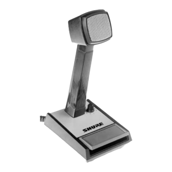
The Shure Model 526T Series II SUPER PUNCH
station microphone is designed for clearer transmission and
improved reliability. This transistorized microphone can be
used to replace ceramic or dynamic, high- or low-impedance
microphones supplied as original equipment.
Model 526T Series II provides crisp, undistorted voice re-
sponse with adjustable volume control for optimum intelligi-
bility of transmission.
The microphone is designed for maximum versatility in
base station operation. It has a momentary or locking press-
to-talk transmit/receive switch for greatest ease of use, and
a modulation level volume control for highest undistorted
output with high- or low-impedance inputs. The supplied six-
wire cable and triple-pole double-throw switch are arranged
for universal microphone-transceiver connection.
The microphone is not affected by heat or humidity, and it
is oustanding in its ability to resist mechanical shocks and
vibration. Its exclusive ARMO-DUR
grease, fumes, salt spray, sun, rust, and corrosion. The "Mil-
lion Cycle" leaf-type press-to-talk switch is designed to with-
stand rigorous operating conditions and constant use.
Microphone Features:
S
Dynamic microphone with transistorized preamplifier
S
Adjustable volume control for optimum transmiter
modulation and maximum intelligibility
2001, Shure Incorporated
27B1468 (AI)
TRANSISTORIZED BASE STATION MICROPHONE
base
case is immune to oil,
Model 526T Series II Super Punch
Microphone User Guide
S
Replaces either ceramic or dynamic original equip-
ment microphones
S
Excellent response for single-sideband transmission
S
Uses readily available 9-volt battery—low current
drain for long life
S
Low hum pickup, minimum susceptibility to RF inter-
ference
S
Momentary or locking press-to-talk transmit/receive
switch –"Million Cycle" leaf-type
S
Universal six-wire cable for instant microphone-trans-
ceiver connection
S
Sturdy, high-impact ARMO-DUR
S
Rugged and dependable under all operating
conditions
BATTERY INSTALLATION
Model 526T Series II uses a 9 Vdc battery (90AJ1371).To
install the battery, proceed as follows:
1. Loosen two screws (located underneath base) holding
battery retaining clip, and remove battery retaining
clip.
2. Connect terminal strap to battery.
3. Insert battery in VELCRO strap of battery retaining
cllip and fasten VELCRO strap.
4. Insert battery retaining clip in base and tighten screws
securely.
CONNECTIONS
Model 527T Series II can be connected to an input (trans-
ceiver, transmitter, or amplifier) of 500 ohms or more. For de-
tailed instructions for connecting the 526T Series II to CB or
ham transceivers. If your unit is not listed in the Guide, con-
tact your dealer or Shure Incorporated for information.
A piece of tubing is attached to the plug end of the cable
for use as a strain relief for plugs with large cable entry holes.
Remove the tubing when not required.
The internal connections of Model 526T Series II are as
shown in Figure 1.
case
Printed in Mexico
Advertisement
Table of Contents

Related Manuals for Shure 526T Series II Super Punch


Summary of Contents for Shure 526T Series II Super Punch
- Page 1 Rugged and dependable under all operating conditions GENERAL BATTERY INSTALLATION The Shure Model 526T Series II SUPER PUNCH base Model 526T Series II uses a 9 Vdc battery (90AJ1371).To station microphone is designed for clearer transmission and install the battery, proceed as follows: improved reliability.
- Page 2 9Vdc The general wiring procedure for tranceiver connections switched to the receiver circuit by a microphone is as follows: switching contact, insulate (wrap with tape) the BLACK lead. Microphone Audio Input Circuit: 4. Connect the YELLOW lead to the loudspeaker ground 1.
- Page 3 Polar Pattern Unsolder the WHITE leads from switch terminals 7 and 8. Omnidirectional Output Impedance Solder the WHITE leads together, and insulate the connection. 5,000 ohms Unsolder the RED cable lead from terminal 3 and Load Impedance solder it to terminal 8. 500 ohms minimum Solder a jumper lead between terminal 7 and the Output Level (At 1,000 Hz with 100 kilohm load)
- Page 4 Printed Circuit Assembly ....90A2721 SHURE Incorporated Web Address: http://www.shure.com 222 Hartrey Avenue, Evanston, IL 60202–3696, U.S.A. Phone: 847-866–2200 Fax: 847-866-2279 In Europe, Phone: 49-7131-72140 Fax: 49-7131-721414 In Asia, Phone: 852-2893-4290 Fax: 852-2893-4055 Elsewhere, Phone: 847-866–2200 Fax: 847-866-2585...
Need help?
Do you have a question about the 526T Series II Super Punch and is the answer not in the manual?
Questions and answers