Table of Contents
Advertisement
Quick Links
Download this manual
See also:
Programming Manual
Advertisement
Table of Contents

Related Manuals for Agilent Technologies N5980A


Summary of Contents for Agilent Technologies N5980A
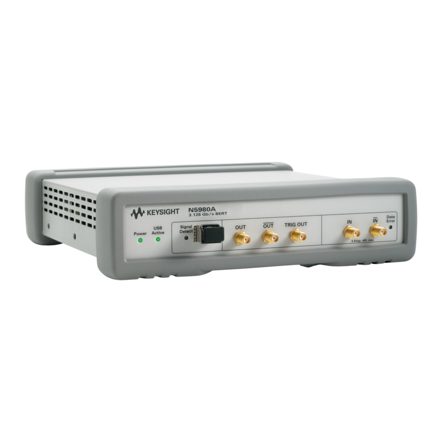
- Page 1 Agilent 3.125 Gb/s Serial BERT N5980A User Guide...
-
Page 2: Restricted Rights Legend
Edition herein. Should Agilent and the user have a separate written agreement with warranty Revision 1.0 May 2006 WARNING terms covering the material in this document... -
Page 3: Safety Summary
Class 1 outlet. Any interruption of the LEDs as per IEC 60825-1. protective (grounding) conductor or Agilent Technologies Inc. assumes disconnection of the protective earth no liability for the customer's failure Environment Conditions terminal will cause a potential shock to comply with these requirements. - Page 4 Australian ACA for EMC control, and laboratory use compliance. CAN/CSA C22.2 No. 1010.1 (1993) UL 3101, 3111 (First Editions). This equipment has also been evaluated to IEC 61010 edition 1 including amendments 1 and 2. Environmental Information N5980A User Guide...
-
Page 5: Table Of Contents
Connect the Instrument 9 Front Panel 9 Rear Panel 10 Install User Software for N5980A 11 To Install the User Software for N5980A 12 To Access N5980A 14 Operating N5980A with the User Interface Introduction 16 Running the BER Test 17... - Page 6 BER 28 Advanced BER 29 Programming Reference Introduction 30 Common Command Summary 30 Agilent N5980A Command Summary 30 SCPI Instrument Command List- Reference 31 Common Commands 31 All Channels 33 SMA Output (Electrical Generator) 34 SFP Output (Optical Generator) 36...
-
Page 7: Introduction
Getting Started Inspect Shipment Connect the Instrument Install User Software for N5980A Operating N5980A with the User Interface Introduction Running the BER Test Setting the Instrument Parameters Viewing the Results Reference for the User Interface... -
Page 8: Getting Started
2.0. This should be done in case .Net Framework 2.0 is not already installed, and internet access is not available. N5980A.msi – The Serial BERT installer package Setup.exe – If your PC doesn’t support autorun, execute this file to run the installation. -
Page 9: Connect The Instrument
SFP modules observe the specifications of the selected device. Make sure that the supported maximum PRBS length, and the maximum data rate matches with the N5980A settings. Make sure that the wavelength of the SFP module, and the cabling are identical, and that the optical power is within the specified limit. -
Page 10: Rear Panel
NOTE and 10 cm at the back. To Connect N5980A Connect the N5980A power cord at the rear panel Power In. Connect the instrument, via USB, to the PC on which the User Interface will be installed. Some USB hubs might decrease performance. If possible, directly connect the NOTE N5980A to your PC. -
Page 11: Install User Software For N5980A
Getting Started Figure 3 Serial BERT setup diagram Install User Software for N5980A The requirements for software installation: Either Windows 2000 Service Pack 4, or Windows XP Service Pack 2 Microsoft .NET Framework 2.0 is automatically downloaded from the Microsoft download center during installation. Alternatively dotnetfx.exe may be run from the installation CD in order to... -
Page 12: To Install The User Software For N5980A
Getting Started To Install the User Software for N5980A Insert the CD in the PC’s CD Drive. Double-click Displays the Welcome screen. The Installer guides you through the installation process. N5980A User Guide... - Page 13 Getting Started Select the folder in which N5980A will be saved. N5980A User Guide...
-
Page 14: To Access N5980A
To Access N5980A To launch N5980A, go to Program File and click on: If there is a N5980A connected to the PC via USB, and the User Software is installed, then the following screen appears: Typical Hardware Initialization duration is between 3 to 5 minutes. - Page 15 Upon completion of Hardware Initialization, the User Interface starts and the following window appears. Demo Offline In Demo Offline mode N5980A need not be connected to the PC. The connection dialog looks like the screen below. Click Demo (Offline) to start the offline version of the GUI.
-
Page 16: Operating N5980A With The User Interface
Operating N5980A with the User Interface 3 Operating N5980A with the User Interface Introduction The graphical user interface runs on the PC, and the screen is divided into two areas; one for setting parameters, and the other for viewing results. -
Page 17: Running The Ber Test
Operating N5980A with the User Interface Running the BER Test The User Software supports a quick pass/fail measurement, which is generally used for testing the DUT in manufacturing. This measurement allows you to count the number of bit errors during a user specified gating time. -
Page 18: Setting The Instrument Parameters
The N5980A Error Detector has two (SFP and SMA) different physical input ports, while only one input port can be analyzed at a given time. The analyzed input can be selected with the User Software. -
Page 19: Advanced
Operating N5980A with the User Interface Advanced To view the Advanced page, click on the File menu and enable the Advanced Mode: The Advanced page has the following settings: In this page you can set SFP and SMA Data Patterns, Error Insertion Rate, and also select Clock Trigger Output for the Generator. -
Page 20: Viewing The Results
Operating N5980A with the User Interface Viewing the Results There are two options for viewing the results, BER and Advanced BER, as shown below. BER displays Gating BER and the Elapsed Gating Time. The Advanced BER page can be opened only when Advanced Mode is enabled. -
Page 21: Reference For The User Interface
Additionally, some information is provided to explain the theoretical background to these measurements. When N5980A is launched the following screen is displayed: File Menu The File menu has the following options. Advanced Mode The Advanced Mode allows you to change the settings, and view the results in the Advanced, and the Advanced BER pages. -
Page 22: Store Setting As
User Software connects to the instrument. This setting is stored individually for each instrument by storing the instrument NOTE serial number in the file name. Exit This closes the session with N5980A. Connection Menu This has the following options: N5980A User Guide... -
Page 23: Connect
In the Available Devices, the list of connected device will appear, and the Connect button will be enabled. Each PC can control only one N5980A. NOTE In Remote Programming Setup, a port number can be selected for the remote programming interface. The instrument will then be accessed via a socket that connects the PC’s IP address and the chosen port... -
Page 24: Info
There are two indicators and a BER bar, see the screen above. These indicators inform you about the following errors: • Bit error in the data stream • Loss of pattern synchronization • Complete loss of data N5980A User Guide... -
Page 25: Ber Bar
The device connected to the BERT has inverted the data pattern. The device has changed the data pattern. Error Detector can sync only PRBS patterns. Clock patterns cannot be measured NOTE by the error detector, and will result in loss of synchronization. N5980A User Guide... -
Page 26: Setup And Advanced Tab
There are different patterns available, for example, PRBS patterns, Clock patterns, and K28.5 pattern. The drop down screen below lists the available patterns. To view all the NOTE patterns use the scroll bar. Level: There are two levels provided, the ECL and the LVDS. N5980A User Guide... -
Page 27: Advanced
The selected pattern will affect the SFP output. SMA Data Pattern: In this drop down list you have the same set of patterns to select from. The selected pattern will affect the SMA output. N5980A User Guide... -
Page 28: Ber And Advanced Ber Tab
This BER Bar indicates the Bit Error during the Gating Period. Once the Gating Period is complete this Bar turns green if the test passes (Gating BER is 0.0), and turns red if the test fails (Gating BER > 0.0). N5980A User Guide... -
Page 29: Advanced Ber
This indicates the number of Errors that occurred during the gating time. Actual Errors This indicates the number of errors that occurred during the last update interval of 200ms. Error Detector Pattern This displays the pattern that is currently being used by the Error Detector. N5980A User Guide... -
Page 30: Programming Reference
Example: SCPI allows: :SOUR1:PATT PRBS7;EADD ONCE N5980A needs: :SOUR1:PATT PRBS7; :SOUR1:PATT:EADD ONCE See Sample Code as an example to control the N5980A from within a remote program. Common Command Summary *TST? *OPC? *RST *IDN? *OPT? Agilent N5980A Command Summary... -
Page 31: Scpi Instrument Command List- Reference
Reads the identification string from the instrument. The format of the identification string is: Agilent Technologies,Product Number,Serial Number,Revision Info Product Number is currently N5980A. Serial Number is read from the instrument hardware (0 if offline). Revision Info consists of: Application Revision (Microsoft w.x.y.z format) Instruments Firmware Revision (Major.Minor, 0 if... - Page 32 *TST? Description Performs the instrument selftest. Returns 0 in case of success and 1 in case of errors during the selftest. Error messages that are discovered during the selftest will be stored in the instrument’s error queue. N5980A User Guide...
-
Page 33: All Channels
Available Data Rates Name Frequency Parameter Fast Ethernet 125.00Mb/s OC-3 155.52Mb/s OC-12 622.08Mb/s OC12 OC-48 2.48832Gb/s OC48 OC-48 with 2.666Gb/s OC48FEC 1 x FC 1.0625Gb/s 2 x FC 2.125Gb/s Gigabit 1.25Gb/s GBE1 Ethernet XAUI 3.125Gb/s XAUI N5980A User Guide... -
Page 34: Sma Output (Electrical Generator)
PRBS 2^7-1 PRBS7 PRBS 2^15-1 PRBS15 PRBS 2^23-1 PRBS23 PRBS 2^31-1 PRBS31 Clock / 2 CLK2 Clock / 4 CLK4 Clock / 8 CLK8 Clock / 10 CLK10 Clock / 16 CLK16 Clock / 20 CLK20 K28.5 K28_5 N5980A User Guide... - Page 35 ECL|LVDS Description This either sets or gets the output level. The output is always AC. Specifying the output level actually changes only the amplitude of the generated electrical signal. Available Output Levels Parameter Level 850mV LVDS 400mV N5980A User Guide...
-
Page 36: Sfp Output (Optical Generator)
PRBS 2^7-1 PRBS7 PRBS 2^15-1 PRBS15 PRBS 2^23-1 PRBS23 PRBS 2^31-1 PRBS31 Clock / 2 CLK2 Clock / 4 CLK4 Clock / 8 CLK8 Clock / 10 CLK10 Clock / 16 CLK16 Clock / 20 CLK20 K28.5 K28_5 N5980A User Guide... - Page 37 1e-6 1e-6 1e-7 1e-7 1e-8 1e-8 1e-9 1e-9 Add Single Error :SOUR2:PATT:EADD ONCE Syntax :SOUR2:PATT:EADD ONCE Description Adds a single error to the generated data stream. This is available even if the cyclic error insertion is active. N5980A User Guide...
-
Page 38: Trigger Output
Error Detector detects a very high error ratio, and tries to synchronize with the incoming data. Response Error Detector Pattern Response PRBS 2^7-1 PRBS7 PRBS 2^15-1 PRBS15 PRBS 2^23-1 PRBS23 PRBS 2^31-1 PRBS31 Error Detector has lost pattern UNKNOWN synchronization. N5980A User Guide... -
Page 39: Synchronization Mode
Description Gets the bit error ratio of the last update interval (approx 200ms). Actual Number of Errors :SENS1:FETC:ECO:DELT Syntax :SENS1:FETC:ECO:DELT? Description Gets the number of errors that have been counted during the last update interval (approx. 200ms). N5980A User Guide... - Page 40 Starts a new gating period. This command will be ignored if a gating period is already in progress. Abort Gating :SENS1:GATE:STAT 0 Syntax :SENS1:GATE:STAT 0|OFF Description This command aborts the currently active gating period immediately. It will be ignored if the gating is not in progress. N5980A User Guide...
- Page 41 :SENS1:GATE:STAT? query after the start of the gating period will report a valid state of the gating progress. There is no need to capture 0-1-0 transitions of the gating progress. Input Selection SENS1:INP Syntax SENS1:INP SFP|SMA Description Selects the input for the error detector. N5980A User Guide...
-
Page 42: Sample Code
Programming Reference Sample Code The following example code shows how to control the N5980A from within a remote program. The example code is implemented in C#. The code snippets show the required code that needs to be added to a user program. - Page 43 (response.IndexOf("\n") != -1) response = response.Replace("\n", "\r\n"); return response; Communicate with the instrument Given the class above, the communication with the instrument can be done like this: using System; using System.Collections.Generic; namespace TBertExample static class Program N5980A User Guide...
- Page 44 [STAThread] static void Main() N5980A instrument = new N5980A(); // Connect to the N5980A software running on the same // PC as this program and that is using port number 5025 instrument.Connect("localhost", 5025); // set the data rate to OC-3 instrument.Send(":freq OC3");...