
Subscribe to Our Youtube Channel
Related Manuals for Teledyne 8800P


Summary of Contents for Teledyne 8800P
- Page 1 Model 8800P TRACE MOISTURE ANALYZER Teledyne Analytical Instruments A Business Unit of Teledyne Electronic Technologies...
- Page 2 Your Representative is: Except as may be provided by contract, this document and all specifica- tions and drawings contained are the property of Teledyne Analytical Instruments, are issued in strict confidence, and shall not be reproduced or copied or transmitted, in any form or by any means, or used as the basis for the manufacture or sale of apparatus, programs, or services without permission.
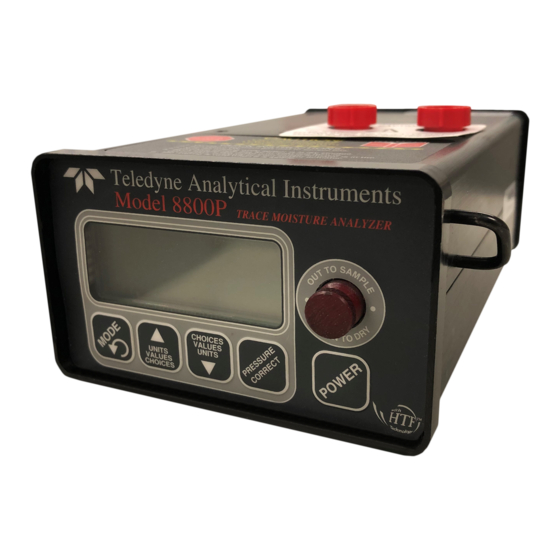
- Page 3 1. Introduction The 8800P is a portable, hand-held, microprocessor controlled, battery operated dew- point meter with built in dry-storage for the sensor. The instrument is ideally suited for all applications, where quick and precise measurements are required. Standard Equipment: Optional Equipment: 1.
- Page 4 • Avoid contaminated sample streams: The 8800P has been designed to allow for fast and precise measurements of dewpoints as low as -100 °C. Therefore, all surfaces in contact with the sample stream are made from electropolished stainless steel. This minimizes the time for the instrument to reach equilibrium with the sample stream, thus speeding up the measurement.
-
Page 5: Principle Of Operation
11.Instrument Case 6. Spring loaded PTFE seals The drawing on the left shows the 8800P with the sensor in dry-storage position. The sen- sor is enclosed in a gas-tight container and surrounded by desiccant. The sample gas passes through the sample chamber and prepares the environment for measurement. - Page 6 A note about dry-storage The dry-storage consist of a stainless steel container filled with desiccant. The elec- tropolished stainless steel sensor guard slides between the dry-storage and the sample cell through a spring energized PTFE seal, assuring maximum possible gas tightness and minimum gas transport between the two chambers when the sensor is moved.
- Page 7 4.1. Sample Hook-up 4.1.1. Fittings The 8800P can be hooked up to the sample gas using a variety of fittings, depending on the application. The instruments’ sample ports are 1/4” VCO female, to assure proper seals for even the lowest dewpoint measurements.
- Page 8 instrument, while still blocking the sample outlet port. • Observe the change in dewpoint indication. The reading will be stable within about 3 minutes, if the dewpoint is increasing. A longer stabilization period will be required, if the dewpoint is decreasing. Make sure the reading has completely stabilized before taking the final reading.
-
Page 9: The User Interface
5.0 The User Interface The user interface consists of a custom LCD display, an audio indicator, 5 push buttons and a sensor actuator. 5.1 Display Conventions 1. To display letters with the 7 segment numeric display, the following pseudo-alpha- numerics are used: Numbers: Letters: A B C D E F G H I... - Page 10 5.2 Operating State Refer to Appendix A for a flow diagram of the operating state. The 8800P is powered ON by pressing the ‘Power’ button until a beep is heard; to activate the backlight, continue to depress the ‘Power’ button until the backlight turns on. Keep in mind that with the back- light on the unit consumes about 5 times more power.
- Page 11 back to atmospheric settings. A long press of the pressure correct button changes the unit back to the Viewing Dewpoint Mode. Pressing the ‘Mode’ button changes the unit to the View/Set Gas Pressure sub-state. The display has the ‘SET’ and ‘PSI’ legends on and alternately shows and the currently set value for the gas pressure.
- Page 12 For example serial number 12345 will be shown as: Pressing the ‘Mode’ button changes the unit to the Viewing Dewpoint Mode. 5.3 Set-up State To enter the Setup State powerup the unit while depressing the Mode key. Refer to Appendix B for a flow diagram of the Set-up State. The set-up state provides the following nine capabilities: 1.
- Page 13 -79.1degC -110.4degF 0.0339LbsH2O/mmscf 0.625ppmV 0.00544g/m3 If an error condition exists the 8800P will respond to the question mark with a phrase describing the error: or SensSaturated or SensShorted SensOpen NOTE: Characters marked in bold are indications of sent or received strings.
- Page 14 If the current loop is not being used, it is safe to connect the DB9 connector directly to a PC; pins 1&9 will not be dammaged or couse dammage. The RS-232 levels are generated by the instrument only when an RS-232 level is detected at the DB9 input.
- Page 15 6.3 Operating from an external Power Supply The external power connector is a 2mm power jack located on the rear of the unit. This input can accept either AC or DC power and is thus polarity independent. The unit requires 13VDC to 25VDC, when operating from external DC power. The unit requires 12VACrms to 25VACrms, when operating from external AC power.
-
Page 16: Automatic Calibration
Do not re-calibrate the unit unless you suspect a problem . The 8800P instrument takes advantage of the pre-designed saturation point of Xentaur HTF sensors. Because Xentaur HTF sensors saturate at a factory designed dewpoint above +20°C, they can be calibrated by simply exposing them to a micro-climate with any... - Page 17 100µ SS wiremesh filter Bottom of VCO fitting, “O” ring visible Bottom view of 8800P with cover open. The sample chamber and desiccant car- tridge are shown cut open to facilitate an understanding of the mechanism and how it is assembled.
- Page 18 9. Special messages, warnings and error indications DISPLAY EXPLANATION REQUIRED ACTION PROM check sum failed. RAM write/read test failed. cycle power / replace battery, Unidentified power-up failure. if problem persists, EEPROM C heck S um F ailed. return to your representative A/D converter failure.
-
Page 19: Appendix A: Flow Diagram Of User Interface In The Operating State
Appendix A: Flow diagram of User Interface in the Operating State For backlight, hold 30 seconds anywhere (other than Power ON initialization and sign on message "Autocal") without key press until it comes on Flashing PSI means pressure corrected dewpoint Toggle Pressure Correct 1/2 sec Display... -
Page 20: Appendix B: Flow Diagram Of User Interface In The Set-Up State
Appendix B: Flow Diagram of User Interface in the Set-Up State For backlight, hold & Power ON initialization until it comes on and sign on message Hi/Lo Test Analog Output by forcing it to high and low end or midpoint. (E. -
Page 21: Appendix C: Relationship Of Instrument Reading And 4-20Ma Output When Lbs Of H 2 0/Million Standard Cft Or Ppmv Engineering Units Are Selected
Appendix C: Relationship of Instrument Reading and 4-20mA output when lbs of H 0/million standard cft or ppmv engineering units are selected. Instrument reading in ppmV 2000 4000 6000 8000 10000 12000 14000 16000 18000 20000 22000 XTR100 1000 1100 Instrument reading in LBS of H2O / million standard cubic feet Instrument reading in ppmV 1000... -
Page 22: Appendix D: Uncertainty In Lbs And Ppmv Calculations
Appendix D: Uncertainty in LBS and PPMV calculations Uncertainty of LBS-H2O calculation due to +/-3˚C measurment accuracy Calculated LBS-H2O in Natural Gas @ STP Uncertainty of ppmV calculation due to +/-3˚C measurment accuracy Calculated ppmV page 20... -
Page 23: Appendix E: Battery Life
Appendix E: Battery Life page 21...
Need help?
Do you have a question about the 8800P and is the answer not in the manual?
Questions and answers