Table of Contents
Advertisement
Quick Links
Advertisement
Table of Contents

Subscribe to Our Youtube Channel
Related Manuals for YOKOGAWA CA700-01


Summary of Contents for YOKOGAWA CA700-01
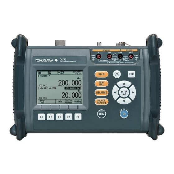
- Page 1 User’s Manual CA700 Pressure Calibrator User’s Manual IM CA700-01EN 4th Edition...
- Page 2 • In this manual, the TM and ® symbols do not accompany their respective registered trademark or trademark names. • Other company and product names are registered trademarks or trademarks of their respective holders. 4th Edition: October 2017 (YMI) All Rights Reserved, Copyright © 2013 Yokogawa Test & Measurement Corporation IM CA700-01EN...
- Page 3 Revisions • 1st Edition: August 2013 • 2nd Edition: September 2015 • 3rd Edition: June 2017 • 4th Edition: October 2017 IM CA700-01EN...
-
Page 4: Conventions Used In This Manual
Conventions Used in This Manual Unit k: Denotes 1000. Example: 100 kS/s (sample rate) K: Denotes 1024. Example: 720 KB (file size) Displayed Characters Bold characters in procedural explanations are used to indicate panel keys and soft keys that are used in the procedure and menu items that appear on the screen. - Page 5 IM CA700-01EN...
-
Page 6: Table Of Contents
Contents Conventions Used in This Manual ....................iii Chapter 1 Features System Configuration ....................... 1-1 Pressure, DC Current, and DC Voltage Source and Measurement Functions ....1-2 Calibration Feature ......................1-5 Saving Data ........................1-8 Communication Feature ....................1-10 USB Feature ........................1-11 Other Features ....................... - Page 7 Contents Chapter 7 Adjusting the CA700 Adjusting the Source Function ..................7-1 Adjusting the Measurement Function ................7-4 Index IM CA700-01EN...
-
Page 8: Chapter 1 Features
Chapter 1 Features System Configuration System Configuration Pressure External pressure se sor USB interface Pressure device Measured data DC voltage or USB Peripheral DC current interface USB storage CA700 Pressure Transmitter /Pressure Switch Index IM CA700-01EN... -
Page 9: Pressure, Dc Current, And Dc Voltage Source And Measurement Functions
The CA700 comes in three types depending on the gauge pressure that can be measured. CA700-01 –80 kPa to 200 kPa CA700-02 –80 kPa to 1000 kPa CA700-03 –80 kPa to 3500 kPa... - Page 10 1.2 Pressure, DC Current, and DC Voltage Source and Measurement Functions Percentage Display By taking the lower limit of the specified span to be 0% and the upper limit to be 100%, the CA700 displays the measured values as percentages along with the measured values themselves. Relative Display (RELATIVE) The CA700 displays the difference between the measured values and the specified reference value (measured value –...
- Page 11 1.2 Pressure, DC Current, and DC Voltage Source and Measurement Functions DC Current and DC Voltage Measurement The available DC current measurement ranges are 20 mA and 100 mA, and the available DC voltage measurement ranges are 5 V and 50 V. Like pressure measurement, the following features are also available.
-
Page 12: Calibration Feature
Calibration Feature The calibration feature is useful for calibrating and adjusting pressure transmitters and pressure switches. Transmitter Calibration The CA700 can generate (source) an input signal to a pressure transmitter and measure the output from the transmitter. If the transmitter input is pressure, you can use a pressure pump to apply the pressure to the transmitter and monitor the pressure from the pressure pump on the CA700. - Page 13 1.3 Calibration Feature Saving Calibration Data You can save calibration data to a file. If you adjust a transmitter, the data before and after the adjustment can be saved to files with the following file names. File Name The name of the file for data before adjustment is MSxxF_y.CSV where Fixed (measurement/source file) Calibration group number (00 to 99) Fixed (data before adjustment)
- Page 14 1.3 Calibration Feature Saved Information The following information is saved in a calibration data file. • Instrument information • Calibration procedure information • Calibration date • CA700 serial number • Calibration result The following types of data are saved as calibration results. •...
-
Page 15: Saving Data
Saving Data Pressure, current, and voltage measurement data, leak rate measurement data, and transmitter or pressure switch calibration data can be saved to CSV files. Saving Pressure, Current, and Voltage Measurement Data There are two ways to save measured values. Save Measured values are appended to a file each time you press the Save function key. - Page 16 1.4 Saving Data Copying and Deleting Data You can copy data in the CA700 to a USB storage device. You can also delete data in the CA700. Index IM CA700-01EN...
-
Page 17: Communication Feature
Communication Feature You can connect the CA700 to a PC through the USB port. Depending on the USB settings, you can remotely control the CA700 from a PC or use the CA700 as a USB device on the PC. Remote Control You can use dedicated communication commands to remotely control the CA700 from a PC. -
Page 18: Usb Feature
USB Feature Host Feature You can connect a USB storage device to the CA700 and copy the measured data in the CA700 to the USB storage device. Only USB memory devices can be connected as USB storage devices. Hard disks and other media cannot be used. -
Page 19: Other Features
Other Features Backlight On/Off To reduce battery consumption, you can turn off the LCD backlight. Auto Power-off When the auto power-off feature is enabled, the CA700 automatically turns off if there is no user interaction for about 60 minutes. Auto power-off is automatically disabled (the icon also disappears) while the CA700 is logging or performing min/max measurement. -
Page 20: Chapter 2 Source And Measure
Chapter 2 Source and Measure Measuring Pressure Procedure WARNING To prevent injury to the user and damage to devices caused by incorrect connection or pressure leakage, be sure to connect tubing correctly to the CA700 pressure input port by following the instructions in the Getting Started Guide, IM CA700-02EN. Selecting the Item under Measurement From the top menu, use the ▲ or ▼ key to select Measure and Source, and press ENTER. - Page 21 2.1 Measuring Pressure Use the ▲ or ▼ key to select P or EXT P, and press ENTER. Functuin: P Sets the unit Turns averaging on and off Turn scaling on and off and set scaling. Turn the alarm on and off and set the alarm. Turns the percentage display on and off Sets the relative display based on the reference value Initializes the settings Confirms the settings...
- Page 22 2.1 Measuring Pressure Setting the Scaling Press the ▲ or ▼ key to select Scaling. ON and OFF appear on the function menu. Press ON (F1) or OFF (F2). If you select ON, simply press ENTER. The scaling setting screen appears. Set the lower span limit. Set the upper span limit. Set the decimal position of span.
- Page 23 2.1 Measuring Pressure Setting the Alarm Press the ▲ or ▼ key to select Alarm. ON and OFF appear on the function menu. Press ON (F1) or OFF (F2). If you select ON, press ENTER. The alarm setting screen appears. Set the lower alarm limit. Set the upper alarm limit. Confirms the settings Use the ▲ or ▼ key to select Alarm Lower, and press ENTER.
- Page 24 2.1 Measuring Pressure Press the or key to move to the digit you want to change, press the ▲ or ▼ key to set the number. To confirm the value, press ENTER. Likewise, set Span Upper. Note The decimal point position is the same as the span decimal point position in Scaling. After entering the values, press Setting Done (F5). To discard all of the % Span settings, press the ESC key.
- Page 25 To measure pressure, select one of the following: Input pressure directly to the CA700 to measure pressure. The following pressure ranges can be measured depending on models: CA700-01 (200 kPa model): -80 to 200 kPa (gauge pressure) CA700-02 (1000 kPa model):...
- Page 26 Scaling By assigning scale values to the pressure at the lower span limit and the pressure at the upper span limit, you can view measured values converted in any physical quantity. Scale value Upper limit (Upper) Lower limit (Lower) Measured value (span) Lower limit (Lower) Upper limit (Upper) When scaling is set to ON, “SCL”...
-
Page 27: Measuring Leak Rates
Measuring Leak Rates Procedure WARNING To prevent injury to the user and damage to devices caused by incorrect connection or pressure leakage, be sure to connect tubing correctly to the CA700 pressure input port by following the instructions in the Getting Started Guide, IM CA700-02EN. Selecting the Measurement Function From the top menu, use the ▲ or ▼ key to select Measure and Source, and press ENTER. - Page 28 2.2 Measuring Leak Rate Use the ▲ or ▼ key to select P LEAK or EXT LEAK(external pressure sensor), and press ENTER. Sets the unit Turns averaging on and off Turn scaling on and off and set scaling. Initializes the settings Confirms the settings Setting Measurement Conditions If necessary, set the measurement conditions. The procedure for setting the range(EXT PEAK), unit, averaging, and scaling and for initializing the settings are the same as in pressure measurement.
- Page 29 2.2 Measuring Leak Rate Setting the Measurement Time Press Time Change (F2). The measurement time edit screen appears. Press ENTER. You can now edit the measurement time. Press the key to move to the digit you want to change, press the ▲ or ▼ key to set the number. To confirm the value, press ENTER. Press Setting Done(F5). The settings are confirmed.
-
Page 30: Generating Dc Current And Dc Voltage
Generating DC Current and DC Voltage Procedure Refer to the Getting Started Guide (IM CA700-02EN), and correctly connect the CA700 to the current or voltage supply device. DC current and DC voltage source is valid when the pressure measurement of Display1 is set to normal pressure measurement (P or EXT P). - Page 31 2.3 Generating DC Current and DC Voltage Generating the Specified DC Current and DC Voltage Output status display Output value to move the position to change the value Confirms the settings Saves measured data (see section 2.1 and 4.1) Starts output Press the key to move to the digit you want to change, press the ▲ or ▼ key to set the number.
- Page 32 2.3 Generating DC Current and DC Voltage Sweeping the Source Value Setting the Source Method After step 7, press Setting (F5). Setting categories appear on the function menu. Function menu Press Step Setting (F3). The source method setting screen appears. Set the lower span limit.
- Page 33 2.3 Generating DC Current and DC Voltage Setting the Source Value Sweep Method Press the ▲ or ▼ key to select Step Type. Sweep methods appear on the function menu. Press Linear (F1) or Step (F2). Confirming the Settings After entering the measurement conditions, press Setting Done (F5). The screen shown in step 1 appears.
- Page 34 2.3 Generating DC Current and DC Voltage Sweeping (Stepping) Manually After step 20, press Step/Sweep (F1). One step down Starts output One step up Upper or lower span limit Press Span 100% (F3) or Span 0% (F3) to set the output value to the upper or lower span limit. Press Step Up (F4) or Step Down (F5) to change the output by the step value specified in the output method.
- Page 35 2.3 Generating DC Current and DC Voltage Explanation Source Function You can select from the following three source functions. mA Source mA Simulate V Source mA Source The CA700 output DC current in the range of 0 to 20 mA. mA Simulate The CA700 can absorb a specified amount of current from a distributor or other external voltage source.
- Page 36 2.3 Generating DC Current and DC Voltage Sweeping The CA700 can vary the source value in the range defined by the lower and upper span limits. You can vary the source value stepwise or linearly. Step (Step) The CA700 varies the source value in steps from the lower to the upper span limit. Linear (Linear) The CA700 varies the source value linearly from the lower to the upper span limit.
-
Page 37: Measuring Dc Current And Dc Voltage
Measuring DC Current and DC Voltage Procedure Refer to the Getting Started Guide (IM CA700-02EN), and correctly connect the CA700 to the device under measurement. DC current and DC voltage measurement is valid when the pressure measurement of Display1 is set to normal pressure measurement (P). - Page 38 2.4 Measuring DC Current and DC Voltage Finishing the Settings After entering the measurement conditions, press Setting Done (F5). The screen shown in step 1 appears. mA MEASURE or V MEASURE mA LOOP Changing the Measurement Range (for mA MEASURE and V MEASURE) Press Range (F1).
- Page 39 2.4 Measuring DC Current and DC Voltage Explanation Measurement Function (Function) There are three measurement functions: mA MEASURE, mA LOOP, and V MEASURE. mA MEASURE: The CA700 can measure DC current in the range of –20 mA to +20 mA or –100 mA to +100 mA.
-
Page 40: Chapter 3 Calibrating The Pressure Transmitter
Connecting to a Pressure Transmitter or Pressure Switch WARNING • Do not apply pressure exceeding the allowable input range. Excessive pressure may cause injury or damage to the instrument. Model CA700-01 CA700-02 CA700-03 Allowable input Negative pressure 2.7 kPa abs 2.7 kPa abs... - Page 41 3.1 Connecting to a Pressure Transmitter or Pressure Switch Pressure transmitter External pressure sensor Pressure pump (91051/91056) Input terminal Loop voltage CA700 *: When use the external pressure sensor Connecting a Pressure Switch to the CA700 Connect the pressure pump output to the pressure switch input and the CA700 input through branching.
-
Page 42: Select The Calibration Procedure
Select the Calibration Procedure Procedure From the top menu, use the ▲ or ▼ key to select Calibrate, and press ENTER. The calibration display appears. Information about the selected calibration procedure (source function, measurement function, number of calibration points, and calibration direction) Press Select Proc.(F2). A list of registered calibration procedures is displayed. Up to 20 sets of procedures can be registered. - Page 43 Setting the Device Information and the Calibration Conditions of the Pressure Transmitter Procedure In the calibration display, press Edit (F1). The calibration procedure setup screen appears. The setup screen is divided into three pages: Transmitter Information, Measure, and Source. Hold down ▲ or ▼ to change the screen. Page Setting the Device Information.
- Page 44 3.3 Setting the Device Information and the Calibration Conditions of the Pressure Transmitter Setting Measurement Conditions Hold down the ▼ key. The display switches to page 2/3 (measurement condition setting display). When the measurement function is set to mA MEASURE, mA LOOP, or V MEASURE Set the measurement function.
-
Page 45: 3.3 Setting The Device Information And The Calibration Conditions Of The Pressure Transmitter
3.3 Setting the Device Information and the Calibration Conditions of the Pressure Transmitter Setting Sensor Type and Range (for external pressure sensor) The Sensor Type is fixed to 16 MPa. The procedure for setting Range is the same as in pressure measurement. See section 2.1. Setting Unit (for Pressure), Averaging, and Scaling These items are the same as with pressure measurement. - Page 46 3.3 Setting the Device Information and the Calibration Conditions of the Pressure Transmitter When the source function is set to EXT P Set the source function. Set the sensor type(fixed to 16MPa). Set the measurement range. Set the unit. Turns averaging on and off Turn scaling on and off and set scaling.
- Page 47 3.3 Setting the Device Information and the Calibration Conditions of the Pressure Transmitter Setting Sensor Type and Range (for external pressure sensor) The Sensor Type is fixed to 16 MPa. The procedure for setting Range is the same as in pressure measurement. See section 2.1. Setting Unit, Averaging, and Scaling (Pressure) These items are the same as with pressure measurement.
-
Page 48: Device Information
3.3 Setting the Device Information and the Calibration Conditions of the Pressure Transmitter Explanation Device Information The device information that you set here is saved to a file along with the calibration data. This is convenient in associating the saved data with the device. Input Characters The number of characters that you can enter is as follows. - Page 49 3.3 Setting the Device Information and the Calibration Conditions of the Pressure Transmitter Tolerance for Pass/Fail Judgment Set the tolerance for making pass/fail judgments on calibration results. The tolerance is set in reference to the 0% and 100% values described above. Tolerance = ±((100% value of the measurement function –...
-
Page 50: Calibrating The Pressure Transmitter
Calibrating the Pressure Transmitter Procedure This section mainly describes the procedure for when Measure is set to mA Loop and Source is set to pressure (P). Selecting the Calibration Procedure In the calibration display, press Select Proc. (F2). The calibration procedure setting display appears. 、... - Page 51 3.4 Calibrating the Pressure Transmitter Saving the Data before Adjustment Press As Found (F3). The display switches to the source and measure value display. Loop On appears on the function menu. If the source function is set to DC current or DC voltage, Source On appears on the function menu. Error at the current calibration point Current calibration point/ total number of calibration points...
- Page 52 3.4 Calibrating the Pressure Transmitter Adjusting the Pressure Transmitter In the calibration display, press Adjust (F4). A display for monitoring the pressure transmitter output appears. Finishes adjustment Outputs the loop power for the adjustment point (current if the source function is set to current, voltage if the source function is set to voltage) Decreases the adjustment point Increases the adjustment point...
- Page 53 3.4 Calibrating the Pressure Transmitter Saving the Data after Adjustment In the calibration display, press As Left (F5). The display switches to the source and measure value display. Error at the current calibration point Current calibration point/ total number of calibration points Using the same procedure as in “Saving the Data before Adjustment,”...
- Page 54 3.4 Calibrating the Pressure Transmitter Explanation Calibration Data File The pressure transmitter calibration data before and after adjustment is saved to CSV files. File Name Calibration data before adjustment: MSxxF_y.CSV Calibration data after adjustment: MSxxL_y.CSV 00 to 99 (calibration group number) Same number between the calibration data file before and after adjustment 0 to 9, sequence number assigned to data files before...
-
Page 55: Setting The Calibration Conditions Of The Pressure Switch
Setting the Calibration Conditions of the Pressure Switch Procedure In the calibration display, press Select Proc. (F2). A list of registered calibration procedures is displayed. Up to 20 sets of procedures can be registered. They are displayed in four windows. Press to change the page and ▲ or ▼ to select the calibration procedure you want to edit. -
Page 56: Index
3.5 Setting the Calibration Conditions of the Pressure Switch Setting the Device Information These items are the same as with pressure measurement. See section 3.3 Setting Measurement Conditions Setting Measurement Functions Set the calibration target output. Use the ▲ or ▼ key to select Function, and press ENTER. The measurement function options are displayed. -
Page 57: Calibrating A Pressure Switch
Calibrating a Pressure Switch Procedure Selecting the Calibration Procedure In the calibration display, press Select Proc. (F2). The calibration procedure setting display appears. Use the key to change the page, and the ▲ or ▼ key to select a pressure switch (P SWITCH) calibration procedure,and press ENTER. The calibration procedure is selected, and the calibration display returns. Switches to the pressure switch calibration procedure information... - Page 58 3.6 Calibrating a Pressure Switch Saving the Data before Adjustment Press As Found (F3). A screen for monitoring the pressure applied to the pressure switch appears. Switch condition Pressure applied to the pressure switch Pressure when the switch opened Pressure when the switch closed Difference between the pressure when the switch opened and that when the pressure switch closed Resistance when the switch closed...
- Page 59 3.6 Calibrating a Pressure Switch Saving the Data after Adjustment In the calibration display, press As Left (F5). A screen for monitoring the pressure applied to the pressure switch appears. Using the same procedure as step 4 and 5, save the calibration data after adjustment. Explanation Calibration Data File The pressure switch calibration data before and after adjustment is saved to CSV files.
-
Page 60: Chapter 4 Saving And Deleting Data
Chapter 4 Saving and Deleting Data Setting How to Save Measured Data This section describes the procedure for setting how to save the pressure, DC current, and DC voltage data that was measured in sections 2.1 and 2.4. Procedure From the top menu, use the ▲ or ▼ key to select Device Setting, and press ENTER. On the Device Setting screen, use the ▲ or ▼ key to select Data Save Setting, and press ENTER. - Page 61 4.1 Setting How to Save Measured Data Setting the Data Save Interval (Valid for Logging) Use the ▲ or ▼ key to select Logging Interval, and press ENTER. The save interval options are displayed. Use the ▲ or ▼ key to select a save interval, and press ENTER. Set the number of data values to save (valid for Logging). Use the ▲ or ▼ key to select Logging Points, and press ENTER. Press the key to move to the digit you want to change, press the ▲ or ▼ key to set the number.
- Page 62 4.1 Setting How to Save Measured Data Explanation Save Method The save method specifies how to save measured pressure, DC current, and DC voltage data. Save: Measured values are appended to a file each time you press the Save function key. Data is saved to the same file until any of the following conditions is met.
-
Page 63: Deleting Files
Deleting Files Procedure From the top menu, use the ▲ or ▼ key to select File, and press ENTER. Use the ▲ or ▼ key to select File Utility, and press ENTER. Use the ▲ or ▼ key to select the file to delete. Press or to scroll by pages. To select multiple files, use the ▲ or ▼ key to select the file you want to delete, and then press ENTER. A check mark appears next the name of the file to indicate that it will be deleted. Likewise, select other files that you want to delete. To clear a check mark, press ENTER again. - Page 64 4.2 Deleting Files Press Delete (F1). A confirmation message will appear. Press ENTER. The selected files will be deleted. To cancel deleting, press ESC. Explanation You can delete files that are saved in the CA700 internal memory. You cannot save more than 100 files of each type of data: Save data files, Logging data files, and calibration data files.
-
Page 65: Copying Files To A Usb Storage Device
Copying Files to a USB Storage Device Procedure Setting the USB Connection From the top menu, use the ▲ or ▼ key to select Device Setting, and press ENTER. Then, use the ▲ or ▼ key again to select Device Setting, and press ENTER. The Device Setting screen appears. Press the ▲ or ▼ key to select USB Connection. Host and Function appear on the function menu. Select to connect to the PC. Select to connect a mass storage device. - Page 66 4.3 Copying Files to a USB Storage Device Copying Files to a USB Storage Device Connect a USB storage device to the CA700 USB port (USB A type). From the top menu, use the ▲ or ▼ key to select File, and press ENTER. Use the ▲ or ▼ key to select File Utility, and press ENTER. Index Use the ▲ or ▼ key to select the file to copy. Press or to scroll by pages.
- Page 67 4.3 Copying Files to a USB Storage Device Explanation Setting the USB Connection The CA700 has a USB port for hosts (A type) and another for functions (mini-B type). Select which connector you want to use. You cannot use the two ports simultaneously. USB for host: Select this option when connecting a USB storage device to the CA700.
-
Page 68: Formatting Internal Memory
Formatting Internal Memory CAUTION If you format the CA700 internal memory, all measured data will be deleted. Before you format the memory, copy important data to a USB storage device or copy to a separate mass storage device using a PC. Procedure From the top menu, use the ▲ or ▼ key to select File, and press ENTER. -
Page 69: Chapter 5 Remote Control
Chapter 5 Remote Control Connecting the CA700 to Your PC USB Port The CA700 has two USB ports. To communicate with a PC, use the mini-B USB port. USB type-B port (Mini-B) Used to control the CA700 from a PC through communication commands or to access the CA700 internal memory from a PC. -
Page 70: Setting The Usb Parameters
Setting the USB Parameters Procedure Setting the USB Connection From the top menu, use the ▲ or ▼ key to select Device Setting, and press ENTER. Then, use the ▲ or ▼ key again to select Device Setting, and press ENTER. The Device Setting screen appears. Press the ▲ or ▼ key to select USB Connection. Host and Function appear on the function menu. Select to connect to the PC. Select to connect a mass storage device. - Page 71 5.1 Setting the USB Parameters Setting the USB Function Press the ▲ or ▼ key to select USB Function. Mass Storage and Comm. appear on the function menu. To remotely control the CA700 with communication commands Select to use the CA700 as a USB storage device on the PC. Press Mass Storage (F1) or Comm.
-
Page 72: List Of Commands
List of Commands Item Command Description Normal User Adjustment Data retrieval Requests to send measured data. Measure and source MS Sets or queries the measurement/source mode. Measurement Sets or queries the measurement range. function Holds or queries the measurement value display. Starts or stops a leak test. -
Page 73: Commands
Commands Command Syntax The command syntax is explained below. Setting/Control Command: Transmission command format Answer: Response data format without response (setting/control) When an error occurs, the same data as the error message ERRm (m = error number) that is displayed on the screen is returned. Queries Command: Transmission command format... - Page 74 5.4 Commands [BSN command] Queries the serial number. Queries the serial number. Normal Adjustment Command = BSN?<CRLF> → Answer = xxxxxxxxx<CRLF> Parameters xxxxxxxxx : serial number [CD command] Sets the source value for adjustment. Sets the source value for adjustment. Normal Adjustment Command = CD<CRLF>...
- Page 75 5.4 Commands [CP command] Sets the adjustment point. Sets the adjustment point. Normal Adjustment Command = CPm<CRLF> → Answer = CPm<CRLF> Parameters 0: +FS adjustment 1: +zero adjustment 2: –FS adjustment 3: –zero adjustment 4: +FS adjustment (monitor measurement) 5: +zero adjustment (monitor measurement) [CR command] Sets or queries the source adjustment value for adjustment.
- Page 76 5.4 Commands [DT command] Sets or queries the date/time. Sets or queries the date/time. Normal Adjustment Command = DTyyyymmddhhmmss<CRLF> → Answer = DTyyyymmddhhmmss<CRLF> Command = DT?<CRLF> → Return = DTyyyy/mm/dd,hh:mm:ss<CRLF> Parameters (default value) yyyy: Gregorian (2013) 4 bytes, mm: month (01) 2 bytes, dd: day (01) 2 bytes hh: hour (00) 2 bytes, mm: minute (00) 2 bytes, ss: second (00) 2 bytes...
- Page 77 5.4 Commands [FMN command] Queries the model number of the external sensor. Queries the model number of the external sensor. Normal Adjustment Command = FMN?<CRLF> → Answer = PM100-x-yy-zz<CRLF> Parameters Basic use code 01 Basic use code 02 Basic use code 03 To set the user calibration date of the external pressure sensor, you need to set Function to EXT P or EXT LEAK.
- Page 78 5.4 Commands [IM command] Sets or queries the status byte detection/mask. Sets or queries the status byte detection/mask. Normal Adjustment Command = IMm<CRLF> → Answer = IMm<CRLF> Command = IM?<CRLF> → Return = IMm<CRLF> Sets whether to detect or mask each status byte bit (queried with the ESC S command;...
- Page 79 5.4 Commands [LP command] Sets or queries the leak period. Sets or queries the leak test leak period. Normal Adjustment Command = LPhhmmss<CRLF> → Answer = LPhhmmss<CRLF> Command = LP?<CRLF> → Return = LPhhmmss<CRLF> Parameters hh: hour (00) 2 bytes, mm: minute (00) 2 bytes, ss: second (00) 2 bytes Default value: 00:10:00 [LT command] Starts or stops a leak test.
- Page 80 5.4 Commands [MS command] Sets or queries the measurement/source mode. Sets or queries the measurement/source mode. Normal Adjustment Command = MSm<CRLF> → Answer = MSm<CRLF> Command = MS?<CRLF> → Return = MSm<CRLF> Parameters m = 0: Measurement mode (default value) 1: Source Mode [OD command] Requests to send measured data.
- Page 81 5.4 Commands [PU command] Sets or queries the pressure unit. Sets or queries the pressure unit. Normal Adjustment Command = PUmn<CRLF> → Answer = PUmn <CRLF> Command = PUm?<CRLF> → Return = PUmn <CRLF> Parameters m = 0: DISPLAY1 item 1: DISPLAY2 item 00: mbar 01: bar 02: Pa...
- Page 82 5.4 Commands [SC command] Sets and queries the scaling. Sets and queries the scaling. Normal Adjustment Command = SCmn,o,p,q,r,s,t,u<CRLF> → Answer = SCmn,o,p,q,r,s,t,u <CRLF> Command = SCm?<CRLF> → Return = SCmn,o,p,q,r,s,t,u <CRLF> Parameter 0: GROUP item A 1: GROUP item B GROUP item A settings 0: OFF (default value) 1: ON Span lower limit...
- Page 83 5.4 Commands [SD command] Sets or queries the source value. Sets or queries the source value. Normal Adjustment Command = SDm<CRLF> → Answer = SDm<CRLF> Command = SD?<CRLF> → Return = SDm<CRLF> Parameters m = Source value DCmA m = 0.000 to 24.000 DCV m = 0.0000 to 5.5000 When the function is set to measurement, ERR13 is returned.
- Page 84 [SY command] Switches between normal mode and user adjustment mode. Switches or queries the normal/adjustment mode. Normal Adjustment Command = SYm<CRLF> → Answer = SYm<CRLF> Command = SY?<CRLF> → Return = SYm<CRLF> Parameters 0: Normal mode (default value) 1: User adjustment mode [TD command ] Sets or queries the number of log points.
- Page 85 [XR command] Queries the MAX range. Queries the MAX range. Normal Adjustment Command = XRm?<CRLF> → Return = XRmn<CRLF> Parameters m = 0: Internal pressure sensor 1: External pressure sensor 0: 200 kPa range 1: 100 kPa range 2: 3500 kPa range 3: 16 MPa range To set the user calibration date of the external pressure sensor, you need to set Function to EXT P or EXT LEAK.
-
Page 86: Status Byte Format
Status Byte Format Device Status Byte Status byte format (see the explanation of the <ESC S> command) bit 7 bit 6 bit 5 bit 4 bit 3 bit 2 bit 1 bit 0 0 (fixed) 1 (fixed) Output error 24 V power Over-range Syntax error Output Measurement... -
Page 87: Connecting The Ca700 To Your Pc As A Usb Storage Device
Connecting the CA700 to Your PC as a USB Storage Device Setting USB Parameters In the USB settings of section 5.2, set USB Connection to Function and USB Function to Mass Storage, and then restart the CA700. If you did not change the USB connection setting, you do not have to restart the CA700. -
Page 88: Chapter 6 Other Settings
Chapter 6 Other Settings Setting the Auto Power-Off Feature and LCD Contrast and Turning the LCD Backlight On and Off Procedure Setting the Auto Power-Off Feature and LCD Contrast From the top menu, use the ▲ or ▼ key to select Device Setting, and press ENTER. Then, use the ▲ or ▼ key again to select Device Setting, and press ENTER. The Device Setting screen appears. - Page 89 6.1 Setting the Auto Power-Off Feature and LCD Contrast and Turning the LCD Backlight On and Off Explanation Auto Power-off When the auto power-off feature is enabled, “AUTO OFF” appears on the screen, and the CA700 automatically turns off if there is no user interaction for about 60 minutes. However, the auto power-off feature is disabled in the following instances.
-
Page 90: Setting The Hart Resistance And The Number Of Pressure Display Digits
Setting the HART Resistance and the Number of Pressure Display Digits Procedure From the top menu, use the ▲ or ▼ key to select Device Setting, and press ENTER. Then, use the ▲ or ▼ key again to select Device Setting, and press ENTER. The Device Setting screen appears. Turns HART resistance on and off Set the number of digits on the pressure display. Index Turning HART Resistance On or Off Press the ▲ or ▼ key to select HART Resistance. - Page 91 6.2 Setting the HART Resistance and the Number of Pressure Display Digits Explanation HART Resistance You can turn the internal 250 Ω resistor on and off. If you want to use 24 V loop power supply or current source in a HART or BRAIN communication system, turn the resistor on. When HART resistance is set to ON, appears on the screen.
-
Page 92: Setting The Decimal Point And The Separator For Csv Data
Setting the Decimal Point and the Separator for CSV Data Procedure From the top menu, use the ▲ or ▼ key to select Device Setting, and press ENTER. Then, use the ▲ or ▼ key again to select Device Setting, and press ENTER. The Device Setting screen 1/2 appears. Keep pressing the ▲ or ▼ key until Device Setting 2/2 appears. Device Setting display 2/2 Set the decimal symbol. Set the separator for CSV data. Index Setting the Decimal Symbol Press the ▲ or ▼ key to select Decimal Point. - Page 93 6.3 Setting the Decimal Point and the Separator for CSV Data Explanation Decimal Symbol You can set the decimal symbol to a period or comma. Separator for CSV Data You can set the separator for the CSV data that will be saved. You can set it to a comma, semicolon, or tab.
-
Page 94: Holding Displayed Values And Displaying Min/Max Values
Holding Displayed Values and Displaying Min/ Max Values Procedure Holding Displayed Values When measured values are displayed on the screen, press HOLD on the CA700 front panel. HOLD appears on the screen, and the measured values are held. You will only be able to use the HOLD keys. -
Page 95: Reference Value And Relative Display
Reference Value and Relative Display Procedure When measured values are displayed on the screen, press RELATIVE on the CA700 front panel. REL appears on the screen, and a relative value based on the reference value is displayed. If the reference value is assigned to the measured value, when you press RELATIVE, the measured value will become the reference value. -
Page 96: Setting The Languge
Setting the Languge Procedure From the top menu, use the ▲ or ▼ key to select Device Setting, and press ENTER. Then, use the ▲ or ▼ key again to select Device Setting, and press ENTER. The Device Setting screen 1/2 appears. Keep pressing the ▲ or ▼ key until Device Setting 2/2 appears. Index Use the ▲ or ▼ key to select Language, and press ENTER. The language options are displayed. Use the ▲ or ▼ key to select the language, and press ENTER. Confirming the Settings Press Setting Done (F5). The settings are confirmed. Explanation Language You can set the language displayed on the screen to English, Japanese, Chinese, or Korean. -
Page 97: Upgrading The Firmware Version Of The Pressure Sensor
Upgrading the Firmware Version of the Pressure Sensor Operation On the top menu screen, use the ▲ or ▼ key to select Device Setting and press the ENTER key. Use the ▲ or ▼ key to select Firmware Upgrade and press the ENTER key. To upgrade the internal pressure sensor or external pressure sensor, press Internal Sensor (F1) or External Sensor (F2), respectively. A message asking whether to upgrade the firmware version will appear. -
Page 98: Adjusting The Source Function
Chapter 7 Adjusting the CA700 Adjusting the Source Function Procedure To adjust the CA700, connect a digital multimeter to the CA700 voltage or current terminals. Use a digital multimeter with sufficient specifications to adjust the CA700. DC voltage DC current Digital multimeter Digital multimeter H(A) - Page 99 7.1 Adjusting the Source Function Adjusting the DC Voltage Use the ▲ or ▼ key to select Voltage Source, and press ENTER. The DC voltage source adjustment screen appears. The CA700 generates 0 VDC. DC voltage source value DC voltage source value measured inside the CA700 Adjust the DC voltage at two points: 0 V and 5 V. Adjust the CA700 DC voltage source value so that it matches the reading on the digital multimeter.
- Page 100 7.1 Adjusting the Source Function Press Done (F5). The internal measurement of 0 V is adjusted. The 5V internal measurement adjustment screen appears. Press Done (F5). The internal measurement of 5V is adjusted. The DC voltage adjustment screen shown in step 2 appears. Press ESC.
- Page 101 The User Adjustment screen appears. Adjust the DC current measurement. Adjust the DC voltage measurement. Adjust pressure measurement. (Contact your nearest YOKOGAWA dealer or service.) Adjust the pressure switch resistance measurement. Adjust the loop power supply current measurement. IM CA700-01EN...
- Page 102 7.2 Adjusting the Measurement Function Adjusting the DC Voltage Measurement Use the ▲ or ▼ key to select Voltage Measure, and press ENTER. The DC voltage measurement adjustment screen appears. Input voltage Switch the measurement range. Adjusting the 5 V Range Check that Input 5V is displayed, and apply 5 VDC from the DC voltage/current generator. Press Done (F5).
- Page 103 7.2 Adjusting the Measurement Function Adjusting the DC Current Measurement After step 1, use the ▲ or ▼ key to select Current Measure, and press ENTER. The DC current measurement adjustment screen appears. Input current Switch the measurement range. Adjusting the 20 mA Range Check that Input 20 mA is displayed, and apply 20 mA from the DC voltage/current generator. Press Done (F5).
- Page 104 7.2 Adjusting the Measurement Function Adjusting the mA Loop Measurement After step 1, use the ▲ or ▼ key to select Loop Power, and press ENTER. The mA loop measurement adjustment screen appears. Input current Generate a sink current of 20 mA from the DC voltage/current generator. The CA700 will generate 24 V. Press Done (F5).
- Page 105 7.2 Adjusting the Measurement Function Explanation Adjustment Points The adjustment points of the measurement function are provided below. Range Generator Output Adjustable Range Lower Limit Upper Limit Voltage Measure 5.000 V 5.0000 V 4.500 V 5.500 V 50.00 V 50.00 V 45.00 V 55.00 V Current Measure...
- Page 106 Index Symbol Page Page %Span .................. 2-4 gauge pressure..............1-2 Page Page Adjust.................. 3-13 HART resistance ..............6-3 adjusting the current simulation ..........7-3 HOLD..................6-7 adjusting the DC current ..........7-3, 7-6 holding displayed values ............6-7 adjusting the DC voltage ..........7-2, 7-5 holds the screen ..............
- Page 107 Index Page Page Next Point ................3-12 unit ..................2-2 number of calibration points ..........1-5 upgrade ................6-10 Number Of Points ..........2-17, 3-8, 3-10 USB Connection ............4-6, 5-2 USB function................. 5-3 USB interface specification........... 5-1 Page USB port ................5-1 PC connection ..............
Need help?
Do you have a question about the CA700-01 and is the answer not in the manual?
Questions and answers