Table of Contents
Advertisement
Advertisement
Table of Contents

Subscribe to Our Youtube Channel
Related Manuals for Fitness Quest Brutus 655

Summary of Contents for Fitness Quest Brutus 655
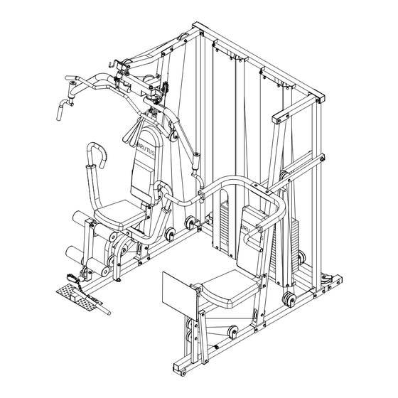
- Page 1 HOME GYM...
-
Page 2: Table Of Contents
Be sure to read through this Owner’s Manual carefully. It is the authoritative source of information about your Brutus ® 655 Home Gym. Retain this manual for future reference. Table of Contents: Important Safety Instructions...3 Comments or Questions &... -
Page 3: Important Safety Instructions
IMPORTANT SAFETY INSTRUCTIONS Read all instructions before using this machine CAUTION: Exercise of a strenuous nature, as is customarily done on this equipment, should not be undertaken without first consulting a physician. No specific health claims are made or implied as they relate to the equipment. Measurements made by the equipment are believed to be accurate, but only the measure- ments of your physician should be relied upon Know your heart rate and / or pulse, and your physician recommended target heart rate training... -
Page 4: Comments Or Questions & Carton Information
Comments or Questions? Dear Customer, Congratulations on your purchase of the Brutus® 655 Home Gym. We’re sure that you will be completely satisfied with the product we invite your comments so that we can hear about your success. Please write or call our Customer Service Specialists at the address or phone number listed below, or contact us on our web site, with any comments or questions you may have. -
Page 5: Hardware Illustrations
Hardware Illustrations Page 1 (49)M8X15 HEX BOLT (47)M10x25mm SCREW (50)3/8"x3/4" HEX BOLT (46)13mm BUSHING (67)3/8" LOCKNUT (48)M8X25 HEX BOLT (52)M8X63 HEX BOLT (70)3/4" BUSHING (69)M8mmLOCKNUT (53)3/8"x2-5/8" HEX BOLT (60)5/8"x5-3/4" SHAFT BAR (61)5/8"x7-3/4" SHAFT BAR... -
Page 6: Hardware Illustrations
Hardware Illustrations Page 2 (56)3/8"x3-1/2" HEX BOLT (66)5/8" LOCKNUT (57)3/8"x4-1/2" HEX BOLT (65)5/8" WASHER (58)3/8"x5-1/8" HEX BOLT (59)3/8"x6-1/8" HEX BOLT... -
Page 7: Parts Identification
(2)RIGHT OBLIQUE (1)RIGHT BASE FRAME BEAM (3)RIGHT (4)LEFT VERTICAL OBLIQUE FRAME FRAME (11)RIGHT TOP (12)LEFT TOP CROSS FRAME CROSS FRAME (18)SEAT (17)FOAM ROD CUSHION Parts Identification Page 1 (7)CENTER BASE (6)LEFT BASE TUBE (A) BEAM (5)LEFT VERTICAL FRAME (14) LEG EXTENSION (13)RIGHT SEAT CUSHION FRAME... - Page 8 (23)LEG (24)SAFETY PRESS CLASP SUPPORT (27)RIGHT (30)LEFT ADJUSTABLE BUTTERFLY ARM PLATE (35)STOP ROD (34)LEFT PRESS (39)DOUBLE (38)CURL BAR PULLEY BRACKET(A) Parts Identification Page 2 (25)BUTTERFLY (26)HANDLE EXTENSION (31)RIGHT (32)PIVOT PULLEY BACKREST BRACKET CUSHION (42)WEIGHT SELECTION ROD(A) (40)DOUBLE PULLEY BRACKET(B) (29)LEFT (28)RIGHT ADJUSTABLE BUTTERFLY ARM...
- Page 9 (71)2" SQUARE (72)2" END PLUG SQUARE END CAP (76) PULLEY (77)TOP PLATE (83)FOAM ROLL (82)RUBBER DONUT (88) BUSHING (87) BUSHING PLASTIC(B) PLASTIC(A) (93)UPPER CABLE Parts Identification Page 3 (73)1"x2" END PLUG (78)7/16"ALLEN (79)WEIGHT CAP SCREW (85)SHORT FOAM GRIPS (89) POP PIN (90)CHAIN HOOK (94) LEG CABLE...
-
Page 10: Parts List
Item Q’ty Part Name Right Base Beam Right Oblique Frame Right Vertical Frame Left Oblique Frame Left Vertical Frame Left Base Beam Center Base Tube “A” Center Base Tube “B” Guide Rod Top Cross Frame Right Top Cross Frame Left Top Cross Frame Right Seat Cushion Frame Leg Extension Frame Left Seat Cushion Frame... - Page 11 NOTES...
-
Page 12: Assembly Instructions
PLEASE READ ALL INSTRUCTIONS CAREFULLY BEFORE ASSEMBLING FIGURE 1 Step 1. Push 2” SQUARE END PLUGS (71) into ends of RIGHT BASE BEAM (1), LEFT BASE BEAM (6), and LEFT OBLIQUE FRAME (4). Step 2. Attach CENTER BASE TUBE “A” (7) to RIGHT BASE BEAM (1) and LEFT BASE BEAM (6) with 3/8”... - Page 13 RIGHT VERTICAL FRAME RIGHT OBLIQUE LEFT FRAME VERTICAL FRAME LEFT OBLIQUE FRAME 3/8” x 3” 2” SQUARE HEX BOLT END PLUG CENTER BASE TUBE 3/8” x 2-5/8” 3/8” HEX BOLT WASHER 3/8” LOCKNUT 2” SQUARE END PLUG 3/8” LOCKNUT CENTER BASE TUBE RIGHT 2”...
- Page 14 FIGURE 2 Step 8. Slide RUBBER DONUTS (82) onto one end of each GUIDE ROD (9) and insert into CENTER BASE TUBE “B” (8). Step 9. Slide a total of 14 WEIGHTS (79), ONE AT A TIME, down GUIDE RODS (9) on the RIGHT BASE BEAM (1) side, with SLOT on bottom and facing forward as shown.
- Page 15 FIGURE 3 Step 17. Push 2” SQUARE END PLUG (71) into end of TOP CROSS FRAMES (11 RIGHT and 12 LEFT). Step 18. Attach RIGHT TOP CROSS FRAME (11) to RIGHT OBLIQUE FRAME (2) with 3/8” x 2-5/8” HEX BOLTS (53), 3/8” WASHERS (62) and 3/8” LOCKNUTS (67). Step 19.
- Page 16 FIGURE 4 Step 20. Push 2” SQUARE END PLUGS (71) into each end of TOP CROSS FRAME (10). Step 21. Place TOP CROSS FRAME (10) into top of VERTICAL FRAMES (3 RIGHT & 5 LEFT) and over GUIDE RODS (9) with SHROUD BRACKETS facing front as shown. Step 22.
- Page 17 FIGURE 5 Step 23. Attach 2” SQUARE RUBBER BUMPERS (81) to RIGHT SEAT CUSHION FRAME (13) with M10 x 25mm SCREW (47). Step 24. Attach RIGHT SEAT CUSHION FRAME (13) to RIGHT OBLIQUE FRAME (2) with 3/8” x 2-5/8” HEX BOLTS (53) 3/8” WASHERS (62) and 3/8” LOCKNUTS (67). Step 25.
- Page 18 FIGURE 6 Step 26. Push 2” SQUARE END PLUGS (71) into each end of LEG EXTENSION FRAME (14). Step 27. Attach LEG EXTENSION FRAME (14) to RIGHT SEAT CUSHION FRAME (13) with 3/8” x 2-5/8” HEX BOLT (53), 3/8” WASHER (62) and 3/8” LOCKNUT (67). Step 28.
- Page 19 FIGURE 7 Step 31. Attach 2” SQUARE RUBBER BUMPER (81) to LEFT SEAT CUSHION FRAME (15) with M10 x 25mm SCREW (47). Step 32. Attach LEFT SEAT CUSHION FRAME (15) to LEFT OBLIQUE FRAME (4) with 3/8” x 2-5/8” HEX BOLTS (53) 3/8” WASHERS (62) and 3/8” LOCKNUTS (67). Step 33.
- Page 20 FIGURE 8 Step 36. Attach RIGHT BACKREST CUSHION (31) to RIGHT OBLIQUE FRAME (2) with 3/8” x 2-5/8” HEX BOLTS (53) and 3/8” WASHERS (62). Step 37. Push 3/4” BUSHINGS (70) into RIGHT BENCH PRESS FRAME (20). Step 38. Attach PULLEY (76) to RIGHT BENCH PRESS FRAME (20) with 3/8” x 6-1/8” HEX BOLT (59), 3/ 8”...
- Page 21 RIGHT PRESS 3/8” WASHER 3/8” x 3” HEX BOLT 3/8” x 6-1/8” 3/8” HEX BOLT 5/8” WASHER 5/8” 5/8” x 7-3/4” SHAFT BAR BUSHING PULLEY FIGURE 8 1” ROUND END PLUG LONG FOAM GRIP 2” SQUARE END CAP RIGHT BENCH PRESS FRAME 3/8”...
- Page 22 FIGURE 9 Step 43. Attach LEFT BACKREST CUSHION (41) to LEFT OBLIQUE FRAME (4) with 3/8” x 2-5/8” HEX BOLTS (53) and 3/8” WASHERS (62). Step 44. Push PLASTIC BUSHINGS “B” (88) into LEFT BASE BEAM (6). Step 45. Push 2” SQUARE END PLUG (71) and 1” x 2” END PLUGS (73) into LEG PRESS SUPPORT (23).
- Page 23 NOTES...
- Page 24 FIGURE 10 Step 50. Attach PIVOT PULLEY BRACKETS (32) to RIGHT OBLIQUE FRAME (2) with M8 x 63mm HEX BOLTS (52), M8 WASHERS (64) and M8 LOCKNUTS (69). Step 51. Attach PULLEYS (76) to PIVOT PULLEY BRACKETS (32) with 3/8” x 2” HEX BOLTS (51), 3/8” WASHERS (62) and 3/8”...
- Page 25 5/8” WASHER 2” SQUARE END PLUG M8 x 25mm HEX BOLT 3/4” BUSHING 3/8” BIG WASHER 5/8” WASHER RIGHT BUTTERFLY PLASTIC BUSHING “A” 1” ROUND END PLUG HANDLE HAND GRIP PIVOT PULLEY BRACKET PULLEY WASHER 5/8” LOCKNUT LOCKNUT 3/8” LOCKNUT BUTTERFLY EXTENSION RIGHT...
- Page 26 FIGURE 11 Step 62. Push 1” x 2” END PLUGS (73) into ends of LEFT BENCH PRESS FRAME (33). Step 63. Push 3/4” BUSHINGS (70) into LEFT BENCH PRESS FRAME (33). Step 64. Attach LEFT BENCH PRESS FRAME (33) to LEFT VERTICAL FRAME (5) with 5/8” x 6-3/4” SHAFT BAR (60), 5/8”...
- Page 27 FIGURE 12 Step 70. Attach SHROUDS (36), with SLOT at bottom, to TOP CROSS FRAME (10) and CENTER BRACE TUBE “B” (8) using 3/8” x 3/4” HEX BOLTS (50) and 3/8” WASHERS (62). CROSS FRAME SHROUD 3/8” WASHER 3/8” x 3/4” HEX BOLT FIGURE 12 SLOT...
- Page 28 FIGURE 13 Step 71. Attach two PULLEYS (76) to LEG PRESS SUPPORT (23) with 3/8” x 4-1/2” HEX BOLT (57), 3/ 8” WASHERS (62) and 3/8” LOCKNUTS (67). Step 72. Attach a PULLEY (76) to four SINGLE BRACKETS with 3/8” x 2” HEX BOLT (51), 3/8” WASH- ERS (62) and 3/8”...
- Page 29 PULLEY CHAIN HOOK PRESS CABLE SINGLE BRACKET PRESS SUPPORT 3/8” LOCKNUT 3/8” LOCKNUT SLOT 3/8” WASHER 3/8” WASHER PULLEY LEFT BASE BEAM SINGLE BRACKET CHAIN PULLEY LEFT OBLIQUE FRAME SQUAT CABLE PULLEY 13mm BUSHING SINGLE 3/8” BRACKET WASHER CABLE LOCK 3/8”...
- Page 30 FIGURE 14 Step 80. Attach two PULLEYS (76) to DOUBLE BRACKET on RIGHT BENCH PRESS FRAME (20) and DOUBLE BRACKET on RIGHT OBLIQUE FRAME (2) with 3/8” x 3-1/2” HEX BOLTS (56), 3/8” WASHERS (62) and 3/8” LOCKNUTS (67). Step 81. Insert PULLEY (76) into SLOT of RIGHT OBLIQUE FRAME (2) and LEG EXTENSION FRAME (14) and fasten with 3/8”...
- Page 31 RIGHT OBLIQUE FRAME DOUBLE PULLEY BRACKET “B” RIGHT BENCH DOUBLE PRESS BRACKET FRAME EXTENSION FRAME FIGURE 14 DOUBLE CABLE PULLEY BRACKET “A” CHAIN SINGLE BRACKET SLOT PULLEY “F” “B” “A” SINGLE BRACKET CHAIN HOOK PRESS CABLE SINGLE BRACKET “J” “H” “K”...
- Page 32 FIGURE 15 Step 88. Insert one BALL end of UPPER CABLE (93) down through one SLOT in RIGHT TOP CROSS FRAME (11) and the other BALL down through other SLOT. Step 89. Place a PULLEY (76) into each SLOT in RIGHT TOP CROSS FRAME (11) and fasten with 3/8” x 2”...
- Page 33 13mm BUSHING 3/8” x 2” HEX BOLT 3/8” WASHER SLOT BALL RIGHT 3/8” ADJUSTABLE LOCKNUT PLATE LEFT BALL ADJUSTABLE PLATE LOCKNUT RIGHT OBLIQUE FRAME FIGURE 15 SLOT UPPER CABLE PULLEY PIVOT PULLEY BRACKET WASHER SLOT BUTTERFLY CABLE DOUBLE PULLEY BRACKET “B”...
- Page 34 FIGURE 16 Step 97. Slide HAND GRIPS (86) over ends of LAT BAR (37) and CURL BAR (38). Step 98. The following items can be attached to BALL end of UPPER CABLE (93) with CHAIN HOOK (90): a. LAT BAR (37) (shown attached) b.
- Page 35 FIGURE 16 Step 100. Apply LABELS to both stacks of WEIGHTS starting with 20lb at top weight as shown. 20 lb. 30 lb. 40 lb. 50 lb. 60 lb. 70 lb. 80 lb. 90 lb. 100 lb. 110 lb. 120 lb. 130 lb.
-
Page 36: Owner's Purchase Record
©1999 and 2000 Fitness Quest Inc. All rights reserved. Brutus ® is a registered trademark of Fitness Quest ® Inc. Made in China. No part of this booklet may be reproduced or utilized in any form by any means, electronic, mechanical or otherwise, without the express written consent of the copyright holder.
Need help?
Do you have a question about the Brutus 655 and is the answer not in the manual?
Questions and answers
where can I order parts for the Brutus 655 ( Bufferfly cable, upper cable and leg cable along with 18 pullies