Mesa/Boogie Mini Rectifier Twenty-Five Owner's Manual
Multi-watt
Hide thumbs
Also See for Mini Rectifier Twenty-Five:
- Owner's manual (54 pages) ,
- Operating instructions manual (24 pages) ,
- Owner operating instructions (11 pages)
Table of Contents
Advertisement
Advertisement
Table of Contents

Related Manuals for Mesa/Boogie Mini Rectifier Twenty-Five


Summary of Contents for Mesa/Boogie Mini Rectifier Twenty-Five
- Page 1 ulti T W E N T Y ~ F I V E Owner’s Manual...
- Page 2 Hello from the Home of Tone Discerning player and all around intuitive human that you are, you’ve put your trust in us to be your amplifier company. This is something we don’t take lightly. By choosing this instrument to be a part of your musical voice, you have become much more than a customer to us, you’re now a lifetime member of the MESA worldwide family.
- Page 3 WARNING: EU: permission from the Supply Authority is needed before connection. • WARNING: Always make sure proper load is connected before operating the amplifier. Failure to do so could pose a shock hazard and may result in damage to the amplifier. • Do not expose amplifier to direct sunlight or extremely high temperatures. • Always insure the amplifier is properly grounded. Always unplug AC power cord before changing fuse, tubes or removing chassis. Use only same type and rating when replacing fuse. • Avoid direct contact with heated tubes. Keep amplifier away from children. • To avoid damaging your speakers and other playback equipment, turn off the power of all related equipment before making the connections. • Do not use excessive force when handling buttons, switches and controls. Do not use solvents such as benzene or paint thinner to clean the unit. • Always connect to an AC power supply that meets the power supply specifications listed on the rear of the unit. Export models: Always insure unit is wired for proper voltage. Make certain grounding conforms with local standards. LOUD! YOUR AMPLIFIER IS EXPOSURE TO HIGH SOUND VOLUMES MAY CAUSE PERMANENT HEARING DAMAGE. Your MESA/Boogie Amplifier is a professional instrument. Please treat it with respect and operate it properly. READ AND FOLLOW PROPER USAGE INSTRUCTIONS...
-
Page 4: Table Of Contents
Multi-Watt Mini Rectifier Twenty-Five TABLE OF CONTENTS OVERVIEW ______________________________________________________________ 5-6 FRONT PANEL CONTROLS Getting Started & Helpful Hints _________________________________________________ 7 CHANNEL MODES Channel 1: Clean / Pushed ___________________________________________________ 7-8 Channel 2: Vintage / Modern ___________________________________________________ 8 Multi-Watt™ Power ___________________________________________________________ 8... -
Page 5: Overview
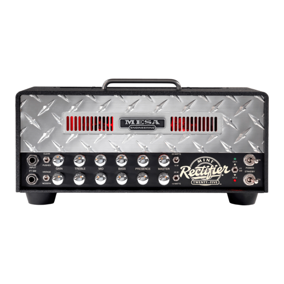
Whether you’re rockin’ hard or putting the immense versatility of the Mini’s four Modes to bear on a variety of styles, you’ll get years of inspiration and enjoyment from this little gas-in-glass-powered jewel. We always strive to build classics, icons that you’ll treasure amongst your most valuable musical instruments. From the feedback we’ve received thus far… it seems the Mini Recto is on its way toward achieving that status. Overview Like its original two channel forefathers, this Recto keeps things straight ahead and easy to navigate. This generation features two footswitchable Channels that each contain two Modes and while it looks basic and drives easy, a world of stylistic versatility lives within these two simple rows of controls. CHANNEL 1 (Green indicator / top channel), focuses on rhythm sounds, both clean and overdriven. The CLEAN Mode delivers sparkling, big-headroom rhythm sounds that breathe with rich, warm air on the bottom end. When driven to clip and combined with the 10 watt Power setting, this Mode misbehaves with real attitude and shines for urgent, yet soulful, Blues solo sounds and furry Rock rhythm. PUSHED aptly describes what to do with the second Mode in Channel one and here you’ll find the next region of gain. With a more stripped EQ and just enough added drive, PUSHED invites aggressive Rock rhythm and Crunch styles to the party and even taunts your mid-gain solo work, especially in the 10 Watt Power setting. FRONT PANEL: MINI RECTIFIER Twenty-Five Head CLEAN 25 WATTS CH 1 PUSHED 10 W INPUT POWER GAIN TREBLE BASS PRESENCE MASTER FT SW STANDBY VINTAGE... - Page 6 CHANNEL 2 (Red indicator / bottom channel), features the iconic Recto high gain sounds in both their faces, the iconic liquid wall of VINTAGE and the aggressive fury of MODERN. VINTAGE excels at thick, high gain chording and single note soloing with an elastic feel and a broad harmonic spread. It has a looser, more organic sound and the overdrive drapes itself around the notes creating a huge, three-dimensional image. VIN- TAGE solo work is further enhanced by the 10 Watt Power position. Here, the attack envelope changes and becomes rounder and more voice-like, while upper harmonics recede slightly to create single note sounds of true beauty. VINTAGE and 10 Watt compliment each other in ways that will open new doors for the Recto that were previously open only to more “well behaved” or “cultured” amps. It may also open wide the eyes of current big-power Recto owners who experience for the first time, what this power range/wiring style does for a sound they had typecast. This is a new and exciting face of Recto and it will surely expand its stylistic footprint. MODERN is the opposite in every way. This aggressive Mode comes right at you - maybe even for you - with stunning attack and a hi-mid bump that keeps things percussive and tracking with hyper-accuracy. It is almost hard to believe that this amount of gain can be infused and yet still deliver a response – especially in bass frequencies – with this much speed and definition. But this is pure Recto and MODERN contributes an equal part to achieving its status as the other most recorded sound in Rock. Needless to say, MODERN is all about all things Heavy and Metal. And while this sound is best demonstrated using the 25 Watt Power setting, be sure not to typecast MODERN too quickly. Using the 10 Watt Power setting to sweeten the mids and soften the attack here, shows another side to MODERN as well that’s more forgiving and vocal, creating a great alternate solo voice with a little more punch and dynamic content. We keep saying it, but it’s hard to overstate the value, effectiveness and stylistic “power” of the Multi-Watt™ Channel Assign- able Power switches. These dedicated wattage range choices unveil different power characteristics and colors – so they are really power “voicing” switches as well. In this Recto, the choice of EL84 power tubes with their amazing clip characteristics, prompted us to explore the different wiring schemes possible. This experimentation led to the 10 Watt Power Mode being wired for Triode operation. This “more vintage” wiring scheme sweetens and rounds out the sound, turning what might otherwise be a lower volume version of the same voice, into more “soulful” Recto experience. Use the 25 Watt setting for its bold attack, tight tracking low end, increased definition and all out headroom. This setting works great with all the sounds and certainly showcases the mightiness in the Mini Rec, shocking unsuspecting players and bystanders alike with power and sonic size. But any time you need to tame this little beast and put a vintage patina of warmth and silkiness around things… kick down to 10 Watts and enjoy a whole new and different world of Recto expression. Jumping around to the Rear Panel, you are met with a lesson in elegant simplicity. Nothing here but the AC Power Socket, the Loop and the Speaker Outputs. While this stands in stark contrast to many other MESA models, including the Mini’s big power Recto brothers, it was a decision based on stylistic, genre-appropriate traditions and not a cost cutting road to a price point. In fact, many fans have requested simpler feature sets from us over the years and the “lunchbox” format is the perfect arena for this conceptual departure. The Effects Loop on the Mini is wired in Series with the dry signal and is Hard Bypassable for those purists who prefer to add processing later in the studio environment. Ironically, our tests have revealed that nearly all players opt for the Loop engaged permanantely, citing enhanced richness, a three dimensional quality and an “openness” to the sound. We are pleased by the added juice these tube stages impart on the signal as it’s no easy feat to add a Loop that enhances - rather than robs -Tone. Well that wraps up the fly-by overview of the Mini. Now it’s time to get into the Modes and Controls of this little dynamo. PAGE...
-
Page 7: Front Panel Controls
FRONT PANEL : Controls & Features CLEAN 25 WATTS CH 1 PUSHED 10 W INPUT POWER GAIN TREBLE BASS PRESENCE MASTER FT SW STANDBY VINTAGE 25 W CH 2 T W E N T Y ~ F I V E MODERN 10 WATTS HELPFUL HINTS... -
Page 8: Channel 2: Vintage / Modern
PUSHED: This mode is a radical departure from the sweet, shimmering blend of the CLEAN modes low gain character. Huge increases in gain in the first stages of the pre-amp produce one of the biggest differences between all four modes and transforms what you thought to be a tame and gentle clean channel into a raging crunch machine. This incredible amount of gain (for a low gain circuit) also creates one of the most expressive solo modes in your Recto. Because there are less stages of gain for the signal to travel through and the tone control network is tuned for the brighter nature of clean sounds, this mode responds more quickly to your pick attack and has a more urgent, snappy feel. Don’t overlook this mode for some of the Mini Recto’s coolest overdrive solo sounds. NOTE: When using PUSHED with the GAIN Control maxed (5:30), avoid setting the TREBLE Control higher than (2:30). Settings above (2:30) may generate microphonic oscillation in certain preamp tubes in the V1 position. This can be avoided altogether by setting the TREBLE Control sensibly when the GAIN Control is maxed. Use the PRESENCE Control for additional brightness. CHANNEL 2: VINTAGE / MODERN VINTAGE: This high gain mode is the famous liquid Recto voice. Its lush harmonic content and fat creamy feel is featured in so many recordings and is now a staple for so many headed to the studio for an album project. Combining this super juicy, expressive preamp with the Rectos’ black magic power section CLEAN creates colors in gain that most players find truly addictive. Single note solo work is effortless as the strings become easy to play with the VINTAGE modes musical and natural tube compression. PUSHED Spend time learning the lower regions of the VINTAGE mode as this is a place where many beautiful INPUT GAIN FT SW sounds live. VINTAGE MODERN MODERN: Aggressive. This is the word that best describes the menacing power of this Recto’smost rebellious of all modes. A take-no-prisoners crushing assault of top end cut and lightning fast re- sponse creates a sound of unparalleled aggression that has set a new standard for hard core sounds. The added tightness of the low end response combined with the radically more present top end keeps the MODERN mode tracking accurately even at extreme gain settings. MULTI-WATT™ POWER Each Channel contains our patented MULTI-WATT™ power switch that allows you to choose either 25 Watts of Pentode wired power or 10 watts of Triode power enabling you to match the power output and feel to each of your foot switchable preamp sounds. The 10 WATT position (switch down) rewires the output tubes to 25 WATTS Triode style wiring for a vintage-voiced and oh-so-clippable 10 watts of power. This produces a smoother, rounder voice that clips with a warmer attack characteristic and a creamier feel. - Page 9 To simplify the GAIN Controls role in shaping the overall tone of the sound we will look GAIN REGIONS Most Balanced at it in two ways: 1) alone and 2) in conjunction with the tone controls. Brightest Warmer & Saturated 1) GAIN Control has three tonal regions: LOW (7:00 - 11:00) provides the cleanest, least saturated sounds and in this region the sound will be brighter and contain more CLEAN upper harmonics lending a three dimensional character to the sound. PUSHED MIDDLE (11:15 - 2:00) enhances the saturation and replaces some of the upper harmon- GAIN ics with a richer, warmer quality and a fuller bottom end response. Not yet fully saturated, VINTAGE this region is the easiest place to get a great sound in both channels. This region contains many of the Recto’s best sounds...especially for soloing due to the crucial blend of an expressive attack combined with ample sustain. MODERN HIGH (2:15 - 5:00) saturates the signal and enhances low and low mid frequencies. While this region provides the maximum saturation and sustain, it also compresses and softens the attack characteristics. For this reason we suggest using this higher region of the GAIN Control sparingly and only when maximum sustain is needed. NOTE: Due to the Recto’s extreme gain potential, the highest regions of the GAIN Control may possibly push the pre-amp tubes past what they can handle, producing microphonic squealing. While we screen and test the tubes your amplifier was shipped with and the tubes in your amp passed our rigourous test, we can’t predict how the tubes will respond over time exposed to extreme gain settings. Your tubes are warranted for a period of 6 months under normal use, but you can save yourself the present and future inconvenience of having to deal with annoying microphonic tube problems by simply using a little common sense...Don’t turn the Gain all the way up! If you must for a specific part or at very low volumes, back down the TREBLE and PRESENCE Controls. Your Recto was de- signed to provide amazing gain and tone at less than extreme settings - removing the need for you to crank everything all the way up. If you are not able to achieve the sound you want at sensible settings on any or all of the controls, your problem may lie elsewhere in the signal chain, i.e. pick-ups, cabinetry, processing etc. Keep in mind you can always call on one of our prod- uct specialist Monday through Thursday and seek some advice should you find yourself struggling to get the sound you want. 2) GAIN - In conjunction with the Tone Controls - Basically, a simple rule applies...as the Gain is increased the Tone control string has less and less effect on the signal until at 5:00, the signal is so saturated that you are getting mostly Gain and very little Tone. Again, this is the reason we suggest using the GAIN Control in its middle region. Here, the Tone control string is very active and provides maximum shaping power - allowing you to dial virtually any sound you desire.
-
Page 10: Mid, Bass And Presence
The MID Control is responsible for the blend of midrange frequencies in the mix and though its effect is not as dramatic as that of the TREBLE Control, it plays an integral part in achieving any sound in your Recto. It is capable of changing the feel dramatically as it blends in a group of frequencies that tend to soften or stiffen the way a sound feels to play. Most players tend to lean in the direction of lower MIDDLE Control settings (7:00 - 11:00) where a scoop in this region pro- duces girth (by letting the Bass become a little more dominant ) and a lack of punch lends a more compressed, even feel to the strings and therefore less apparent resistance to the pick. As the MIDDLE Control is increased, (11:30 - 1:30) the sound is rounded-out and filled-in with a focused midrange attack appearing rather quickly. As you would guess, the feel starts to change – becoming slightly more resistant. Above this region the MIDDLE Control could be used to compensate for either weaker pick-ups or for times when a specific deficiency is created either by an extremely high setting of other tone controls, or a physical anomaly in the room. While these MIDDLE Control settings (2:00 - 5:00) can ADDS PUNCH TO introduce added gain and create enhanced focus, the trade-off will be a stiffer, more forward, WEAKER PICK-UPS SCOOPED AND less compressed feel. EASY TO PLAY Channel 1 utilizes a different MIDDLE Control than that of the Channel 2 with a custom-designed taper and value. In its low range (below 12:00) it functions as a normal midrange control with a taper suited to blending fine increments of these frequen- cies. Most players lean toward a fairly radical scoop (7:00 - 10:30) for clean playing, preferring to let Treble and Bass remain dominant, thus producing the signature sparkle and breath essential for a pristine clean sound. As Channel 1’s MIDDLE Control is swept past 1:00, it starts to add gain in these midrange frequencies adding cut and punch. As the top end of the control is reached, (3:00 - 5:00) it becomes an additional gain control capable of taking both CLEAN and PUSHED modes to extremes. Experiment with this cranked region in conjunction with conservative settings of the other tone controls to balance both sound and feel. While this added flexibility may make Channel 1’s MIDDLE Control a little more tricky to learn at first, it will become quite valuable as you start to realize the power of this super versatile channel. BASS Last, but not least in the string of tone controls, we come to the BASS. This control works similarly in both channels in that it determines the amount of low frequencies present in a sound. However, the actual frequencies and style of lows it mixes in changes with the channels. Like the MIDDLE Control, it falls in line signal-wise after the TREBLE Control and the same scheme applies. When the TREBLE Control is set high, the effectiveness of the BASS and MIDDLE Controls is reduced. If the TREBLE Control is set low, these two controls become dominant. For the most balanced sound and a balance of power between the three rotary tone controls, try to use the TREBLE Control in its middle ranges. This scenario produces nearly equal representation of all the frequencies on the tone controls and provides a great neutral starting point for further tweaking. -
Page 11: Master
dently of the other rotary tone controls and is crucial in voicing the Modes. It is a powerful global BRIGHT & tone control. Lower PRESENCE Control settings darken and, in fact compress the signal, which AGGRESSIVE works well to fatten single note solo sounds, giving them girth and focus. Some of the best lead sounds in your Recto will find the PRESENCE Control in its lower regions where a balanced, vocal WARM & VOCAL response is achieved. PRESENCE One example of this would be when dialing up Bluesy solo sounds in the CLEAN Mode. Here, it is helpful to add gain early in the preamp with the GAIN and TREBLE set higher (5:00 & 2:00) than normal and then roll back the PRESENCE (9:00 – 10:00) to get the sound to warm up again. This scheme can be repeated throughout all the modes and also in reverse - where the PRESENCE is higher and the TREBLE is reduced. That said, many of the best sounds are achieved with both TREBLE and PRESENCE straying above 12:00 noon only occasionally, as they both pack powerful frequencies that can be dangerous at the top of their range. Higher settings unleash the mighty roar of your Mini Recto and produce brighter, more pointed sounds that will cut through a mix. This can be great for sparkling clean sounds in Channel 1 and more aggressive crunch rhythm sounds in PUSHED, VINTAGE and MODERN. MASTER This control is the feed from the end of the pre-amp to the driver stage and the Effects Loop. As you can see, each Channel is fitted with its own MASTER Control, enabling the two channels relative volumes to be matched regardless of their extremely different sound styles and gain signatures. The MASTER Control makes MOST SENSIBLE RANGE possible a wide range of sounds through its ability to use very low GAIN settings at high EASIEST TO BALANCE CHANNELS REASONABLE FX LOOP SIGNAL LEVELS volumes and conversely, high GAIN settings at low volumes and everywhere in between. 25 WATTS Again, we suggest using the MASTER Control in its sensible ranges (9:00 - 2:00). Here, the channels will be easier to match with each other and the Effects Loop will see more reasonable signal levels. - Page 12 REST AREA PAGE...
-
Page 13: Speakers
I V E ANDBUILT IN ETALUMA 2 x EL 84 7,602,927 fuse Y N A A T T RETURN 4 OHM CAUTION: CHASSIS SURFACE MAY BE HOT! SPEAKERS One 4 Ohm and one 8 Ohm jack is provided for speaker interfacing. MESA/Boogie cabinets are built wired to 8 Ohms unless custom ordered or modified by an outside party (i.e. a previously owned cabinet). One 8 Ohm cabinet should be connected to the 8 Ohm output. When using two 8 Ohm MESA cabinets, connect one cabinet to the 4 Ohm output and “daisy chain” the second cabinet by coming out of the first cabinet’s Paralleled Out jack into the second cabinet’s input jack (MESA cabinets provide a Parallel jack for this purpose). SEND 8 OHM If you are using non-MESA cabinets with your Mini Recto, it is very important to know your cabinet’s impedance and make sure you are connecting speakers correctly and safely to the amp. LOOP Failure to connect speakers correctly can cause expensive damage to tubes, transformers and the amp in general. ALWAYS make sure to connect your cabinet correctly to your amp. Check out... - Page 14 A power tube short or failure is often the cause of a blown fuse. Position yourself behind the amplifier and follow the cold start procedure mentioned in the STANDBY switch section of this manual. Watch the power tubes as you flip the STANDBY to the ON position. If a power tube is going bad or is arcing you will often see it as you power up! Flip the STANDBY switch to Standby immediately and replace the faulty power tube and the fuse as necessary. If you see nothing abnormal as you move the STANDBY switch to ON, it is possible that a power tube shorted ‘temporarily’ and caused the blown Fuse. Occasionally, whether from just luck or from cooling down, a short in a power tube ‘reconnects’ itself temporarily and can operate normally again… but this tube should be considered faulty and replaced as soon as possible to ensure uninterrupted per- formance. If you can identify a tube that is arcing or shorting by the method mentioned above and the tubes have minimal use, consider replacing the obviously faulty or failed tube and leaving the others installed. If you haven’t changed tubes for a while after heavier use, this failure may be telling you it’s time to change all your power tubes. Save any working but used tubes as your new spares. Spare fuses (of the proper type and rating) are a must for the fabled cord bag along with spare tubes. Always have both on hand – at the gig or at home – since tubes decide when it’s time to stop working. Spare tubes and fuses can be worth their weight in gold should you ever experience a tube failure. PAGE...
-
Page 15: Factory Sample Settings (2 Channels)
FACTORY SAMPLE SETTINGS Sample Settings #1: TITLE: Sweet Clean (CH1) / Soulful Solo (CH2) 25 WATTS CLEAN CH 1 10 W PUSHED INPUT GAIN TREBLE BASS PRESENCE MASTER POWER STANDBY FT SW VINTAGE 25 W CH 2 MODERN 10 WATTS Sample Settings #2 TITLE: Fat Clean (CH1) - Page 16 FACTORY SAMPLE SETTINGS Sample Settings #5: TITLE: Rock Clean (CH1) / Liquid Gain Solo (CH2) 25 WATTS CLEAN CH 1 10 W PUSHED INPUT GAIN TREBLE BASS PRESENCE MASTER POWER STANDBY FT SW VINTAGE 25 W CH 2 MODERN 10 WATTS Sample Settings #6 TITLE: Tight Crunch (CH1) / Blistering Lead (CH2) 25 WATTS...
- Page 17 FACTORY SAMPLE SETTINGS Sample Settings #9: TITLE: Rock Rhythm (CH1) / Ridiculous Gain Lead (CH2) 25 WATTS CLEAN CH 1 10 W PUSHED INPUT GAIN TREBLE BASS PRESENCE MASTER POWER STANDBY FT SW VINTAGE 25 W CH 2 MODERN 10 WATTS Sample Settings #10: TITLE: Tight Gain Rhythm (CH1) / Lo Power Lead (CH2) 25 WATTS...
-
Page 18: Personal Setting Sheets
PERSONAL SAMPLE SETTINGS FACTORY SAMPLE SETTINGS TITLE: 25 WATTS CLEAN CH 1 10 W PUSHED INPUT GAIN TREBLE BASS PRESENCE MASTER POWER STANDBY FT SW VINTAGE 25 W CH 2 MODERN 10 WATTS TITLE: 25 WATTS CLEAN CH 1 10 W PUSHED INPUT GAIN... - Page 19 PERSONAL SAMPLE SETTINGS FACTORY SAMPLE SETTINGS TITLE: 25 WATTS CLEAN CH 1 10 W PUSHED INPUT GAIN TREBLE BASS PRESENCE MASTER POWER STANDBY FT SW VINTAGE 25 W CH 2 MODERN 10 WATTS TITLE: 25 WATTS CLEAN CH 1 10 W PUSHED INPUT GAIN...
- Page 20 PERSONAL SAMPLE SETTINGS FACTORY SAMPLE SETTINGS TITLE: 25 WATTS CLEAN CH 1 10 W PUSHED INPUT GAIN TREBLE BASS PRESENCE MASTER POWER STANDBY FT SW VINTAGE 25 W CH 2 MODERN 10 WATTS TITLE: 25 WATTS CLEAN CH 1 10 W PUSHED INPUT GAIN...
-
Page 21: Tube Description & Task Charts
PAGE... -
Page 22: Tube Noise & Microphonics
TUBE NOISE & MICROPHONICS You may occasionally experience some form of tube noise or microphonics. Cer- tainly no cause for alarm, this quirky behavior comes with the territory and the Tone. Much like changing a light bulb, you don’t need a technician to cure these types of minor user serviceable annoyances and in fact, you’ll be amazed at how easy it is to cure tube problems...by simply swapping out a pre-amp or power tube! First may we suggest that you set the amplifier up on something so that you can get to the tubes comfortably without having to bend down. It also helps to have adequate lighting as you will need to see the tube sockets clearly to swap tubes. Use caution and common sense when touching the tubes after the amplifier has been on as they may be extremely hot! If they are hot and you don’t want to wait for them to cool off, try grasping them with a rag and also note that the glass down around the bulbous silvery tip is considerably less hot which makes it easier to handle. Gently rock the tube back and forth as you pull it away from its socket. DIAGNOSING POWER TUBE FAILURE There are two main types of tube faults: shorts and noise. Both large and small tubes may fall prey to either of these problems but diagnosis and remedy is usually simple. If a fuse blows, the problem is most likely a shorted power tube and shorts can either be mild or severe. In a mildly shorted tube the electron flow has overcome the control grid and excess current flows to the plate. You will usually hear the amp become distorted and begin to hum slightly. If this occurs, quickly look at the power tubes as you switch the amp to STANDBY and try to identify one as glowing red hot. It is likely that two of a pair will be glowing since the “shorted” tube will pull down the bias for its adjacent mates, but one tube may be glowing hotter — and that one is the culprit. The other two are often fine — unless they’ve been glowing bright red for several minutes. Because there is no physical short inside the tube (just electrons rioting out of control) merely switching to STANDBY for a few moments then back to ON will usually cure the problem...at least temporarily. Watch the tubes carefully now. Should the problem recur, the intermittent tube will visibly start to over heat before the others and thus it can be identified. It should be replaced with one from the same color batch, shown on its label. Call us and we will send one out to you. The severe short is not nearly so benign. In the worst cases, a major arcing short occurs between the plate and the cathode with visible lightning inside the glass and a major noise through the speaker. If this is seen to happen, IMMEDIATELY turn the amp to STANDBY. By this time the fuse probably will have blown. Such a short is usually caused by a physical breakdown inside the tube including contaminate coming loose or physical contact (or near contact) between the elements. Replace it and the fuse with the proper slo-blo type and power up the amp using the power up procedure as we described earlier in this manual. TUBE NOISE Often caused by contamination within in a tube, the culprit can usually be identified, and by lightly tapping on the glass, you will probably hear the noise change. Hearing some noise through the speakers while tapping on the 12AX7’s is normal however. And the one nearer the INPUT will always sound louder because its output is being further amplified by the second 12AX7. -
Page 23: Diagnosing Pre-Amp Tube Problems
DIAGNOSING PRE-AMP TUBE PROBLEMS Because your amplifier is an all tube design, it is quite possible that you will at some point experience minor pre-amp tube noise. Rest assured - this is no cause for alarm and you can take care of the problem yourself in a matter of minutes by simply swapping tubes. Let us begin by saying; It is a “very good” idea to keep at least a couple of spare pre-amp tubes on hand at all times to insure uninterrupted performance. These minor pre-amp tube problems can take many forms but can generally be described in two categories: Noise and Microphonics. Noise can be in the form of crackling, sputtering, white noise/hiss and/or hum. Microphonic problems usually appear in the form of a ringing or high pitched squealing that gets worse as the gain or volume is increased thus are more noticeable in the higher gain “HI” modes. Microphonic problems are easily identified because the problem is still present even with the instruments’ volume off or unplugged altogether - unlike pick-up feedback which ceases as the instru- ment is turned down. Microphonic noise is caused by mechanical vibration and shock: think of banging a microphone around and you’ll understand where the word came from. The best way to approach a pre-amp tube problem is to see if it occurs only in one specific mode or channel. This should lead you to the tube needing replacement. Then all that remains is to swap the suspect tube for a known good performer. If you cannot narrow down the trouble to a specific mode or channel, the problem may be the small tube that drives the power tubes which is operational in all modes and channels. Though rare, a problem with the driver tube would show up in all aspects of performance - so if you can’t narrow the problem down to being mode or channel specific, you may want to try replacing the driver tube. Driver problems generally show themselves in the form of crackling or hum in all modes of performance and/or weak overall output from the amplifier. Occasionally an anemic driver tube will cause the amplifier to sound flat and lifeless, but this is somewhat uncommon, as worn power tubes are a more likely suspect for this type of problem. Sometimes making the diagnosis is more trouble than it’s worth and it’s faster and easier to merely replace the small pre-amp tubes ONE AT A TIME with a replacement known to be good. But MAKE SURE you keep returning the tubes to their original socket until you hit the one that cures the problem. You’ll notice that tubes located nearer to the INPUT jack always sound noisier...but this is because they are at the start of the chain and their noise gets amplified over and over by the tubes that follow. The tube that goes into this “input socket” (usually labeled V1) needs to be the least noisy of the bunch. The tube that goes at the end of the preamp chain - just ahead of the power tubes - can be quite noisy without causing any problem at all. The tubes in your amp have already been located in the most appropriate sockets and this is why you should NEVER pull them all out at once and ALWAYS swap them one at a time. ALWAYS return a perfectly good tube to its original socket. Also it’s a good idea to put the amp on STANDBY when swapping tubes to reduce the heat build up in the tubes themselves and to prevent explosive noises (which can still occur even if you are pulling the tubes away from their sockets gently) from coming through the speaker. Remember, take your time, be patient and chances are real good that you can fix your amp yourself by finding and replacing the bad tube. It kills us to see someone who has shipped their amp back to us...and all it needed was a simple tube replacement! If you must send back your amp, remove the chassis from the cabinet by unscrewing the four mounting bolts on the bottom top. The chassis then slides back like a drawer and comes out from the back. Remove the big power tubes and mark them according to their location from left to right 1, 2 etc. They need to be wrapped separately with plenty of wadded up newspaper around them and put in a smaller box within the larger carton. Remove the Rectifier tubes and wrap them also. You can leave the preamp tubes in or remove them and wrap them separately being sure to label their location. (See Tube Task Chart.) To wrap the chassis, use plenty of tightly wadded up newspaper so there is at least six inches of “crush space” between the chassis and the cardboard box. Bubble wrap also works well, but please DON’T use styrene peanuts - they will shift during transit and get lodged inside your electronics as well as allowing your amp to end up at the bottom of the box unprotected and... -
Page 24: Speaker Impedance & Possible Hook-Up Schemes - Amplifier To Speaker Cabs
SPEAKER IMPEDANCE MATCHING & HOOK-UP GUIDE: IMPEDANCE Wiring up speakers to provide the most effective load and making sure that all of them are in phase will help in creating the best sound possible. This is not too difficult, as long as you understand a few things about loading and how to connect your speakers to provide an optimal resistive load. MESA/Boogie amplifiers can handle 4 and 8 ohms effectively. Never run below 4 ohms in a tube amplifier unless you are absolutely certain that the system can handle it properly; this can cause damage to the Output transformer. A few amplifiers can handle 2 ohms effectively without damaging them (for example the MESA’s Bass 400+). You can always have a higher resistance (16 ohms, for example) without damaging results, but too low of a resistance will likely cause problems. MIS-MATCHING: When running a higher resistance (for example: 8 ohm output into 16 ohm cabinet), a slightly different feel and response will be eminent. A slight mismatch can provide a darker smoother tone with a little less output and attack. This response is a result of the amplifier running a bit cooler. Sometimes when using more than one cabinet a mismatch will be the only option. WHAT IS MY CABINET’S IMPEDANCE? If you have only a single speaker, you just match that single speakers impedance to the amplifier, and you are done. In many cases, you will have a number of speakers, and then you must calculate the “load” that the amplifier will need to support. There are generally three ways to wire multiple speakers together. They are as follows: SERIES: When you wire (hook-up) speakers in Series, the speakers resistance (as measured in ohms) is additive - i.e. putting two 8 ohm speakers in Series results in a 16 ohm load. NEGATIVE = POSITIVE = Speaker B = 8 Ohms Speaker A = 8 Ohms... - Page 25 SPEAKER IMPEDANCE MATCHING & HOOK-UP GUIDE: (Continued) PARALLEL: When wiring in parallel, the resistance of the speakers decreases. Two 8 ohm speakers wired in (hooked- up) Parallel results in a 4 ohm load. It’s easy to calculate the effect of a resistive load when all the speakers are all the same resistance. It is really not suggested to wire different resistive load values in Parallel (8 and 4, 16 and 8 etc.) The formula for figuring the total impedance in Parallel is the multiplication of the two loads divided by the sum of the two loads - i.e. putting two 8 ohm speakers in Parallel results in a 4 ohm load. Connect the Positive side of Speaker A to the Positive side of Speaker B - Connect the Negative side of Speaker A to the Negative side of Speaker B. Speaker A Speaker B 8 Ohms 8 Ohms NEGATIVE POSITIVE Total Load = 4 Ohms All 4 Spkrs. are 8 Ohms COMBINATION OF SERIES & PARALLEL: SPEAKER A SPEAKER B...
- Page 26 WIRING SCHEMES...Amplifier to Speaker Cabinets Partial back view of amplifier Partial back view of amplifier 8 OHM 4 OHM 8 OHM 4 OHM 8 Ohm Cabinet 4 Ohm Cabinet Partial back view of a Mesa amp Partial back view of amplifier 8 OHM 4 OHM 8 OHM...
- Page 27 8 OHM 4 OHM 8 OHM 8 Ohm 8 Ohm SERIES BOX PARALLEL BOX CORRECT 4 Ohm 16 Ohm 4 Ohm 16 Ohm CORRECT MATCH MATCH 4 Ohm Cabinet 4 Ohm Cabinet 16 Ohm Cabinet 16 Ohm Cabinet NOTE: Both Series and Parallel boxes may be purchased through Mesa/Boogie by contacting Customer Service: 707-778-6565, Mon-Thurs 9am-5pm PST PAGE...
- Page 28 8 Ohm Cabinet 8 Ohm Cabinet 8 Ohm Cabinet SAFE MISMATCH Partial back view of amplifier 8 OHM 4 OHM 8 Ohm PARALLEL BOX 16 Ohm 16 Ohm 16 Ohm Cabinet 16 Ohm Cabinet 16 Ohm Cabinet SAFE MISMATCH NOTE: Both Series and Parallel boxes may be purchased through Mesa/Boogie by contacting Customer Service: 707-778-6565, Mon-Thurs 9am-5pm PST PAGE...
-
Page 29: Bias Adjustment By Randall Smith
BIAS ADJUSTMENT A Feature Article by Randall Smith BEAM- Here’s a question we often hear: CONFINING CATHODE ELECTRODE GRID ..SCREEN “Why doesn’t MESA put bias adjustments in their amplifiers?” ..GRID PLATE .. - Page 30 BIAS ADJUSTMENT (Continued) voltage and current are: When you scrape your feet across a carpeted floor in dry, wintery conditions, your body can become charged with 50,000 to 100,000 volts of static electricity. And when you reach for the door knob, a spark jumps and you feel it! The voltage is super high but the current (measured in micro-amps) is tiny - otherwise you would die from electrocution. Contrast this with your car battery, which puts out a mere 12 volts. You can lay your hands right across the terminals and not feel a thing. Yet the amount of current available can run to several hundred amperes .. enough to turn over a cold engine and get it started. So current and voltage are two totally separate electrical parameters — though when you multiply them together, you get POWER, which is measured in watts. When you set the bias of an amplifier, you are adjusting the static VOLTAGE at the control grid of the tube in order to produce a desired amount of idle CURRENT flowing to the tube’s plate. A small change in grid voltage, produces a large change in the amount of current flowing — and that’s basically how a tube works. Say that again because it’s super important: A small change in voltage at the grid causes a large change in current flowing to the plate. See, that’s the essence of amplification: A small change causing a large change. And here it’s a small voltage change causing a large current change. The bias conditions are what determines how much current flows through the big power tubes when you’re not playing. And what drives your speakers is fluctuations in that current flow when you ARE playing. If the amount of current increases and decreases 440 times per second, then you’ll hear an A note. If the fluctuations in current flow are large and still at 440 per second, you’ll hear an A that is LOUD! But for purposes of biasing, it’s the amount of “plate current” flowing with no signal applied that’s important. Unfortunately current is hard to measure because the circuit must be interrupted — as in “cut the wire” — and the meter spliced “in series” with the broken circuit. But measuring VOLTAGE is easy. It is not necessary to interrupt the circuit because a voltage reading can be taken in PARALLEL with the circuit intact. Thus, as a matter of convenience, most bias settings are given in volts at the grid ... even though current through the plate is the important factor. In fact plate current is so inconvenient (and dangerous) to measure that Fender doesn’t even state what the correct value should be. They only give the grid voltage that will produce that current. (That’s the minus 52.) But that only happens if the tubes being used are “in spec.” As long as the tubes ARE “in spec”, the right bias voltage will always give the correct plate “CURRENT” — but then there’s no need for the bias voltage to be adjustable! If the tubes are NOT in spec, then the only proper way to re-set the bias is to cut the circuit and measure the current while adjusting the bias ... but no manufacturer I know even STATES the desired current value! Be that as it may, when the original bias voltage is altered far enough, it will compensate for the tube’s abnormal performance and the correct amount of idle cur- rent flow may then be restored. Clearly this is something most repair techs should not attempt. Some newer amps have LED indicators connected to the circuit which will turn on when the right threshold of current flow has been reached. This is an improvement, and almost worthy if you’re willing to accept resistors and lights added into your amplifier’s audio path — which we aren’t. The other “advantage” of this system is that it allows some amp manufacturers to avoid matching their power tubes. The thinking is that adjusting the bias to each tube separately eradicates the inherent differences between the tubes by insuring that the same current flows through each one.
- Page 31 BIAS ADJUSTMENT (Continued) Some of the other recommended biasing, “methods” — such as -”.. tubes running red hot, increase the bias .. sounds harsh and runs too cool, turn it down ...” are guesswork at best. Luckily, one of the great things about tube amps is that they can usually stand some abuse without causing any real harm ... at least not immediately. But don’t these alterations imply that you are second-guessing the amp designer and that there’s a better set of operating conditions that the designer missed but the tube sellers have discovered? Now some players may like the sound of their amp altered by tubes with extreme characteristics and with the bias set to help compensate. But often it is the mere novelty of change that they’re really responding to and when the amp goes back to the proper original way, we’ve seen them be far happier still! Because every part in every one of our designs has been meticulously evaluated, compared and stressed over — no matter how seemingly insignificant it might be. And with every design we look for a “sweet spot” where all the parameters — including the bias — come together to give the best sonic performance, consistently and reliably. Every part and voltage is important — yet no one complains that these other parameters aren’t available for tinkering. Consider our patented Simul-Class circuitry where there are two different bias voltages used for separate pairs of power tubes ... and changing one voltage also changes the other. Great care goes into getting this just right and we think we’d be asking for trouble to have it adjustable for the world to play with ... unless you like paying to have your amp messed up. Sorry, I meant to say, “Uh, ... your amp needed biasing.” If that doesn’t appeal to you, then merely plug a matched set of MESA tubes into one of our amps and you’re ready for tone. Guaranteed. You’d be amazed at the number of service calls we field every day that lead to a diagnosis of out-of-tolerance, non-spec tube problems. To think these would be prevented by including a bias adjustment is something of an insult to you and us. If you put the wrong size tires on your car, do you think changing the pressure will make them right? Please, don’t think this is a blanket indictment of the other guys selling tubes — it isn’t. And their tubes aren’t all bad either. It just doesn’t make sense to pay more of your hard earned cash for tubes that were probably made in the same Russian or Chinese factory and which have the possibility of being outside the performance window we select for your amp. And it pains us to hear the hype and mystique built up around biasing when twenty-five years of evidence affirms our decision to make bias circuits that “never need adjustment”. How much money and trouble that has saved MESA/Boogie players you couldn’t estimate. Our rigorously tested and hand selected tubes are available at your nearest MESA/Boogie Pro Center or from us directly. Nobody offers better price, quality or warranty than we do ... so why swerve? Cheers! Randall Smith Designer & President MESA/Boogie Ltd. PAGE...
-
Page 32: Triodes, Pentodes & Irishmen By Randall Smith
ON TRIODES, PENTODES & IRISHMEN: A Look Into The Inner Workings of the Vacuum Tube: A Feature Article by Randall Smith With apologies to Friends and Relatives from the Emerald Isle - who will make their appearance soon enough - the humor which follows is dedicated to the memories of Spec McAuliff and Fae (Rafael) McNally, two of the True Greats. As their numerical references suggest, the terms Diode, Triode and Pentode indicate the number of elements within the vacuum tube i.e. two, three or five. All tubes also require a filament or heater which is not included in the count. Its purpose is to excite electrons from the cathode coating by raising the temperature such that they are able to boil out of the electron-rich coating material and form a cloud of free electrons in the vacuum space surrounding the cathode. Although the term filament and heater are often used interchangeably, there are specific differences: A filament is a directly heated cathode where cathode coating is applied directly to the heating element. Examples are 5U4 twin diode rectifier and 300B triode amplifier tubes. A heater, on the other hand, is a heating element which is separate from the cathode and is usually inserted within the tubular cathode sleeve. Examples are 12AX7 twin triode amplifier and 6V6 or EL84 beam power pentode tubes. In all cases this fundamental aspect of each tube’s construction is clearly visible, especially when the heating element is glowing red hot. The cathode, then, would be considered the first numbered element because it is the source of the electrons. The word itself is from the Greek literally meaning completely down, which implies a sense of central origin - like the center of the earth where Tone begins. It might be said that an ecstatic audiophile experiences a positive catharsis, his soul being purified when his system transports him to Audio Nirvana. The only trouble with taking this positive imagery too far is that the cathode is, unfortunately, negative... at least electrically speaking. However this is easily remembered since virtually all musicians and audiophiles have also experienced the more common negative catharsis when they emerge from the emotional rebirth kicking and screaming in rage and frustration. Once heated, the intrinsically negative electrons are energetic little fellows of almost no mass. Thus they may be accelerated almost instantaneously and will travel through a vacuum a nearly the speed of light. Being of like, negative charge, they tend to repel one another and thus within the electron cloud surrounding the cathode, there is much jostling and elbowing as each one tries to maintain his distance from all the others... unless there is a strong and universal attraction from an outside influence. Visualize, if you will, a group of sub-atomic Irishmen milling about and in a repellent, negative state of mind. All are scowling and none wants to have anything to do with the other. Now introduce a strong attraction say, a public bar, and you can easily picture an orderly, if rapid movement of the lot in a single direction. This is what happens when a positively charged element called the anode or plate is introduced into the vacuum. The plate is the large metal element most prominently visible through the glass of an electron tube. It is the outermost element of a tube’s structure and it surrounds all the others. The cathode is at the center radiating electrons outwards. As higher and higher positive voltage is applied to the plate, the attraction for the electrons surrounding the cathode is increased and with noth- ing standing in the way, full uninhibited flow to the plate occurs...sort of like removing the doors and offering free drinks to the crowd of surly Irishmen milling around outside. As electrons flow to the plate, the space charge will continually be replenished by further ‘boiling’ of the hot, electron-rich cathode as you can easily imagine other Irishmen impatiently taking up the places of those who’ve gone inside - until the entire village is deserted. - Page 33 ON TRIODES, PENTODES & IRISHMEN: (Continued) But back to the electron flow. If the electrons are strongly attracted to a positively charged plate, then it follows that they are strongly repelled by a negatively charged plate and they are. Thus, if an alternating current - such as comes from a transformer - is applied to the plate, electrons will flow only during the times when the plate is positively charged. During periods of negative plate charge, electron flow is stopped and the space charge of electrons remains compressed in the area around the cathode. Thus a diode tube - one with a cathode and an anode - is mostly used to rectify alternating current into direct current by pass- ing it without restriction, but in one direction only. This also explains why closing time is strictly enforced at Irish pubs: During normal operation, the traffic flow is similarly unimpeded and uni-directional toward the bar and this process rectifies the work- day negativity. It goes without saying that no one leaves as long as the atmosphere around the bar remains positively charged. TRIODES This section is a continuing technical treatise on the workings of Irish Pubs but to make it easier for the layman to understand, it is explained in terms of vacuum tube technology. Enter the original bar - free beer and no doors. Well, it turns out that some control over the flow can be a necessary and useful advantage. This led to the invention of those swinging lou- vered saloon doors which are open at the top and bottom. They are patterned after the control grid of the vacuum tube, which is a loosely wound coil of thin wire located between the cathode and the plate. In a Triode the plate is always positively charged with high voltage D.C. and even though the grid is blocking the path, those negative electrons can still FEEL the strong attraction - just as the Irishmen can see in through the louvers of the bar doors. They know what pleasures lie beyond, but to get there requires overcoming the negative influences controlling the access. This negative influence is typically called a Bias. In electronic terms that means the grid is supplied with a voltage which is slightly MORE NEGATIVE than the already negative electrons. The more negative the Bias, the more it tends to neutralize the attraction of the plate and repel the electrons back toward the cathode. The Irish can be similarly charged with Bias, but unless you are Irish yourself, this type of Biasing may be more difficult to understand. The effect is similar though: The more negative the Bias, the more it impedes forward progress. Generally speak- ing though, the electronic Bias of the grid is easier to overcome, and for two main reasons: First, the Bias is set - like the bar doors - to allow some passage. Second, the grid is mostly NOT THERE, like the louvered doors which are mostly open spaces. Unlike the plate which is solid, the grid is like a coiled bed spring. It can create a repelling field but mostly it’s empty space in between widely separated windings of wire. It’s very easy to control the electrons as they pass through the grid’s force field: Changing the grid voltage only slightly will have an enormous effect on how much current flows through...and that’s what AMPLIFICATION is: a small change in voltage at the grid causing a large change in current flowing to the plate. The purpose of the louvered bar doors is similar to that of the grid, namely, to give momentary pause while still revealing the promise within. Hesitation mostly gives way to temptation, but there are those few stalwart Irishmen who think twice and de- cide to come back later. Most just pause slightly then go on through. That is the purpose of the bar doors: to prevent everyone from crowding in all at once - and as the door is made less of a barrier, wider spaces between the louvers, more of the bar’s attractive influence is felt outside thus amplifying the customer flow and increasing the crowd at the bar. PENTODES Occasionally though, bar doors - even the louvered type - were found to be too effective, and too many cus- tomers turned away. Something further was needed to increase the attraction of the bar and overcome the resistance created by the door. Thus the cocktail waitress was invented.
- Page 34 ON TRIODES, PENTODES & IRISHMEN: (Continued) the screen grid, they discover...there’s almost nothing there. The path they’re on has them aligned to zing straight through the spaces BETWEEN screen grid windings. So rather than a close and personal encounter, they just fly on past - and once they’re out that far, there’s no stopping them. The influence of the plate takes over and - being solid metal and of the highest positive attraction - it is at this final destination that the electrons congregate. Thus the proper cocktail waitress - visible through the louvers - is scantily clad so as to be all the more effective at reinforcing the attractive influence of her bar and by being located in between the door and the bar, she serves as bait to lure customers past the door’s negative influence. Once through the door however, it is the rare Irishman who actually comes in personal con- tact with the cocktail waitress as, for all intents and purposes, she - like the screen grid - turns out to be a vanishing illusion. Yet, having come this far, the solid influence of the bar itself now takes over and attracts the customers to congregate, having happily reached their destination. If you’re still following this and haven’t lost track of the count, you’ll know we’re still one element short of the five needed to make a Pentode. This last part is a pair of beam-confining shields which being negatively charged, serve to direct the flow right toward the plate. This is much the way a short entrance hall to the bar prevents wandering accidentally into the Men’s room on the way. Once at the bar though, the circuit is complete and the process of soul-nourishing works its ritual magic. Biases having been overcome, illusory nightingales having vanished, the spirits truly soar and the once surly Irishmen now are filled with warmth, wit and kindred friendship, enjoying the music and glowing nicely with their heaters on. With appreciative thanks to the inhabitants of the Land of the Leprechaun, we have now concluded our little diversion into the mechanics of proper bar lay-out. Randall Smith Designer / President MESA/Boogie Ltd. PAGE...
-
Page 35: Parts Chart
Front RECTIFIER MINI Back RECTIFIER MINI PAGE... - Page 36 PAGE...
- Page 37 Thank you for trusting MESA/Boogie to be YOUR amplifier company. We wish you many years of toneful enjoyment from this handbuilt, all tube instrument. PAGE...
- Page 38 1317 Ross Street Petaluma CA 94954 Customer Service 6565 Fax 707 1503 09 / 21 / 11...
Need help?
Do you have a question about the Mini Rectifier Twenty-Five and is the answer not in the manual?
Questions and answers