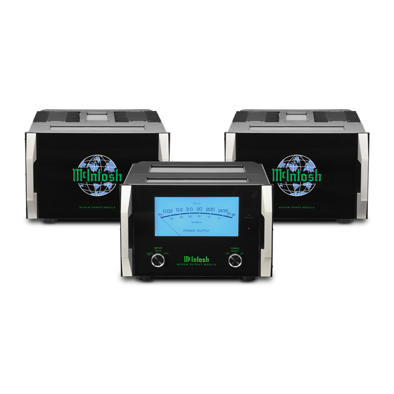
McIntosh MC2KW Connection Diagram
Output module and power module input and control connection diagram
Hide thumbs
Also See for MC2KW:
- Owner's manual (32 pages) ,
- Connection manual (2 pages) ,
- Service manual (28 pages)
Advertisement
Quick Links
2
A
MC2KW Output Module and Power Module Input and Control Connection Diagram
Note: Refer to the MC2KW Owner's Manual page 4 for additional connection information.
Connection Legend:
Data Cable*-
Digital Signal Cable -
Sensor/Keypad Cable -
Interconnect Cable -
Power Control Cable* -
Ground Wire -
Audio Signal Cable -
AC Power Cords -
Video Signal Cable -
Loudspeaker Cable -
RF Signal Cable -
*
2 conductor shielded with 1/8 inch stereo mini phone plug on each end.
McIntosh Controller
McIntosh Preamplifier
McIntosh Tube Preamplifier
McIntosh Laboratory, Inc. 2 Chambers Street Binghamton, New York 13903-2699 Phone: 607-723-3512 FAX: 607-724-0549
MC2KW Output Module (Right Channel)
Connect to second
MC2KW Output
Module (Left Channel)
Power Control In
MC2KW Power Module (A)
Part No. 04106500
MC2KW Power Module (B)
Advertisement

Subscribe to Our Youtube Channel
Summary of Contents for McIntosh MC2KW
- Page 1 MC2KW Output Module and Power Module Input and Control Connection Diagram Note: Refer to the MC2KW Owner’s Manual page 4 for additional connection information. MC2KW Output Module (Right Channel) Connection Legend: Data Cable*- Digital Signal Cable - Sensor/Keypad Cable -...
- Page 2 MC2KW Output Module and Loudspeaker Connection Diagram Note: Refer to the MC2KW Owner’s Manual page XX for additional connection information. McIntosh Loudspeaker (Left Channel) Connection Legend: Data Cable*- Digital Signal Cable - Sensor/Keypad Cable - RS232 Cable - Power Control Cable* -...


Need help?
Do you have a question about the MC2KW and is the answer not in the manual?
Questions and answers