Troy-Bilt TB90BC Operator's Manual
2-cycle gasoline trimmer / brushcutter
Hide thumbs
Also See for TB90BC:
- Operator's manual (80 pages) ,
- Parts list (2 pages) ,
- Specification sheet (1 page)
Table of Contents
Advertisement
Quick Links
TROY:BILT
°
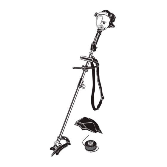
2-Cycle Gasoline
Trimmer /
Brushcutter
Model TB9OBC
IMPORTANT:READ
SAFETY RULES AND INSTRUCTIONS
CAREFULLY
NOTE: For users on U.S. Forest Land and in the states of California, Maine, Oregon and Washington. AU U.S. Forest Land and the state of California
(Public Resources Codes 4442 and 4443), Oregon and Washington require, by law that certain internal combustion engines operated on forest brush
and/or grass-covered
areas be equipped with a spark arresto[, maintained in effective working order, or the engine be constructed,
equipped and
maintained for the prevention of fire, Check with your state or IocaI authorities for regulations pertaining to these requirements. Failure to follow these
requirements could subject you to liability or a fine. This unit is factory equipped with a spark arrestor, if it requires replacement, Accessory Part 791-
180890 Spark Arrestor Screen is available by contacting the service department at Troy-Bilt LLC, P.O. Box 361131 Cleveland, Ohio 44136-0019.
TROY-BILT
LLC, P.O. BOX 361131, CLEVELAND,
OH 44136-0019
PIN
792-10820 (01/02 rev. PO0)
PRINTED IN USA
Advertisement
Table of Contents

Related Manuals for Troy-Bilt TB90BC


Summary of Contents for Troy-Bilt TB90BC
- Page 1 This unit is factory equipped with a spark arrestor, if it requires replacement, Accessory Part 791- 180890 Spark Arrestor Screen is available by contacting the service department at Troy-Bilt LLC, P.O. Box 361131 Cleveland, Ohio 44136-0019.
- Page 2 Content Page Calling Customer Support ..........Rules for Safe Operation ..........Know Your Unit ............Assembly Instructions ..........Oil and Fuel Information ............ Starting/Stopping Instructions ..........Operating Instructions ..........Maintenance and Repair Instructions ......... Accessories and Replacement Parts ......... Cleaning and Storage ............Troubleshooting Chart .............
-
Page 3: Before Operating
• Use only 0.105 inch (2.667 mm) diameter genuine WHILE OPERATING Troy-Bilt LLC replacement line. Never use metal- reinforced line, wire, or rope, etc. These can break off • Never start or run the unit inside a closed room or and become a dangerous projectile. - Page 4 • Use only genuine manufacturer's replacement parts and necessary. accessories for this unit. These are available from your authorized service dealer. Use of any non Troy-Bilt • Clean cutting blades with a household cleaner to LLC parts or accessories could lead to serious injury to remove any gum buildup.
- Page 5 OTHER SAFETY WARNINGS • Never douse or squirt the unit with water or any other liquid. Keep handles dry, clean and free from debris. • Never store the unit, with fuel in the tank, inside a Clean after each use see Cleaning and Storage building where fumes may reach an open flame or instructions spark.
- Page 6 SYMBOL MEANING • OIL Refer to operator's manual for the proper type of oil. • THROWN OBJECTS AND ROTATING CUTTER CAN CAUSE SEVERE INJURY WARNING: Do not operate without the cutting attachment shield in place. Keep away from the rotating cutting attachment. •...
- Page 7 As a brushcutter; Cutting weeds and light bush of up to 1/2 inch in Starter Rope Grip diameter. Shaft Grip Other optional accessories may be used with the TB90BC. See list of add-ons on page 14. Throttle Lock-C On/Off Stoic Throttle Control...
-
Page 8: Installing And Adjusting
INSTALLING AND ADJUSTING THE J-HANDLE While holding the unit in the operating position (Fig. 3), position the J-handle to the location Place the J-handle between the top and middle that provides you the best grip. clamp pieces (Fig. 1). Tighten the clamp screws evenly, until the J-handle is secure. - Page 9 REMOVING AND INSTALLING CUTTING Output Shaft Shaft Bushing Hole ATTACHMENT SHIELD • Remove the cutting attachment shield when using the unit as a brushcutter. WARNING: The cutting attachment shield should NOT be installed when operating unit with a blade. Remove the cutting attachment shield before removing or Output Shaft...
- Page 10 Install the Cutting Blade Align the shaft bushing hole with the locking rod slot and insert the locking rod into the bushing hole (Fig. 8, Pg. 9). always wear gloves while handling or ARNING: To avoid serious personal injury, Put the blade retainer and nut on the output shaft. installing the blade Make sure that the blade is installed correctly.
- Page 11 3. Whileholding the locking rod,loosen thenuton Cutting Attachment thebladebyturning it clockwise witha 5/8inch closed-end o r socketwrench (Fig.14). 4. Remove t henut,bladeretainer, a ndblade.Store the nutandbladetogether f orfutureuseina secure Blade Retainer place.Storeoutof reach of children. Install the Cutting Attachment 5. Align the shaft bushing hole with the locking rod slot and insert the locking rod into the shaft bushing hole.
-
Page 12: Mixing Ratio
NOTE: One gallon (3.8 liters) of unleaded gasoline mixed Definition of Blended Fuels with one 4 oz. (120 ml.) bottle of Troy-Bilt 2 Cycle Today's fuels are often a blend of gasoline and oil makes a 32:1 fuel/oil ratio. -
Page 13: Starting Instructions
STARTING INSTRUCTIONS Start/On (I) On/Off Stop Control Throttle Lock-Out ventilated area outdoors. Carbon monoxide O) - exhaust fumes can be lethal in a confined area. WARNING: Operate this unit only in a well- WARNING: Avoid accidental starting. Be in the starting position when pulling the starter rope (Fig. - Page 14 OPERATING THE EZ-LINK SYSTEM While firmly holding the add-on, push it straight into the EZ-Link coupler (Fig. 20). The EZ-Link system enables the use of these optional add-ons. NOTE: Aligning the release button with the guide recess Blower/Vacuum ......BV720r will help installation (Fig.
-
Page 15: Holding The Trimmer
HOLDING THE TRIMMER Each time the head is bumped, about 1 inch (25.4 ram.) of trimming line is released. A blade in the cutting attachment shield will cut the line to the proper length if body protection and strap to reduce the risk excess line is released. -
Page 16: Decorative Trimming
DECORATIVE TRIMMING ARNING: The blade continues to spin after I Decorative trimming is accomplished by removing all the engine is turned off. The coasting blade vegetation around trees, posts, fences, etc. can ser ous y cut you facc denta y touched. Rotate the whole unit so that the cutting attachment is at •... -
Page 17: Maintenance
Bump Knob clockwise (Fig. 27). Inspect the bolt inside the bump knob to make sure it moves freely. Always use geniune Troy-Bilt rM0.105 in. (2.667 mm) Replace the bump knob if damaged. replacement line. Line other than specified may make the Remove the inner reel from the outer spool (Fig. - Page 18 5. Check the indexing teeth on the inner reel and outer SplitLine Installation spool for wear (Fig. 29). If necessary, remove burrs or Take approximately 20 feet (6.1 m) of new trimming replace the reel and spool. line. Insert one end of the line through one of the two holes in the inner reel (Fig.
-
Page 19: Air Filter Maintenance
13. Insert the ends of the line through the eyelets in the outer spool and place inner reel with spring inside the Lever outer spool (Fig. 35). Push the inner reel and outer spool together. While holding the inner reel and outer spool, grasp the ends and pull firmly to release the line from the holding slots in the reel. -
Page 20: Spark Arrestor
4. Applyenough cleanSAE30oilto lightlycoatthe filter(Fig.39). Spark Exhaust Arrestor Gasket Fig. 39 5. Squeeze the filter to spread and remove excess oil (Fig. 40). Muffler - Front Side Muffler - Back Side Fig. 41 Reinstall the spark arrestor by pressing it into the recessed hole on muffler's back side. -
Page 21: Carburetor Adjustment
CARBURETOR ADJUSTMENT The idle speed of the engine is adjustable through the Air Filter/Muffler cover (Fig. 43). NOTE: Careless adjustments can seriously damage your unit. An authorized service dealer should make carburetor adjustments. Check Fuel Mixture Idle Speed Screw Old and/or improperly mixed fuel is usually the reason for the unit not running properly. - Page 22 REPLACING THESPARKPLUG Use a Champion RDJ7Y spark plug (or equivalent). The correct air gap is 0.020 inch (0.5 mm}. Remove the plug after every 25 hours of operation and check its condition. 1. Stop the engine and allow it to cool. Grasp the plug 0.020 in.
- Page 23 CLEANING LONG TERM STORAGE If the unit will be stored for an extended time, use the following storage procedure. always turn your trimmer off and allow it to cool Drain all fuel from the fuel tank and drain into a I_lb WARNING: TOavoid serious personal injury, before you clean or do any maintenance...
- Page 24 ACTION CAUSE On/Off Stop Control is in OFF position Turn On/Off Stop Control to ON Empty fuel tank Fill fuel tank with properly mixed fuel Primer bulb wasn't pressed enough Press primer bulb fully and slowly 5-7 times Engine flooded Use starting procedure with EZ-Start Lever in the RUN position, Pg.
- Page 25 Engine Type ..............Air-Cooled, 2-Cycle Stroke ................ 1.25 in. (31.75 mm) Displacement ..............1.9 cu in. (31 cc) Clutch Type ................Centrifugal Idle Speed RPM ..............2,800 - 3,600 rpm Operating RPM (Trimmer) ............6,100 - ]0,400 Operating RPM (Brushcutter) ............
- Page 27 • In order to file a claim, go to your nearest authorized TROY-BILT Service Center. Warranty service or repairs will be provided at all authorized TROY-BILT Service Centers.
- Page 28 (90) days from the date of original retail amount of the purchase price of the product sold. purchase for any Troy-Bilt product that is used for rental or Alteration of the safety features of the product shall void commercial purposes, or any other income-producing this Warranty.
Need help?
Do you have a question about the TB90BC and is the answer not in the manual?
Questions and answers