Table of Contents
Advertisement
Safety Instructions
& Operator's Manual for
REAR ENGINE RIDING MOWER
SERIES 22
MODELS
281222BE
301222BE
3314522BVE
331522KVE
MODEL
NUMBER
EXPLANATION
CUTTING WIDTH
ENGINE HP
SERIES DESIGNATION
13311sl221KIvIEI
I
I
ENGINE OPTIONS
ENGINE TYPE
ENGINE MODEL
28 -28" Cutting Deck
12 - 12.0 HP Engine
30 - 30" Cutting Deck
145 - 14.5 HP Engine
33 -33" Cutting Deck
15 - 15.0 HP Engine
22 - Series Designation
B - Briggs Engine
V - Over Head
K - Kohler Engine
Valve
E - Electric
Start
Thank you for buying a SNAPPER Product!
Before operating your machine, read this manual carefully and pay
particular attention to the "IMPORTANT
SAFETY INSTRUCTIONS"
on Pages 2 & 3. Remember that all power
equipment
can be dangerous
if used improperly.
Also keep in mind that SAFETY requires careful use in
accordance with the operating instructions and common sense!
SNAPPER, McDonough,
GA., 30253
U.S.A.
COPYRIGHT
© 2001
SNAPPER
INC.
ALL RIGHTS RESERVED
MANUAL No. 7-4390 (Rev 1, 8/27/01)
Advertisement
Chapters
Table of Contents
Troubleshooting

Related Manuals for Snapper 301222BE SERIES 22


Summary of Contents for Snapper 301222BE SERIES 22
- Page 1 K - Kohler Engine Valve 33 -33" Cutting Deck 15 - 15.0 HP Engine Thank you for buying a SNAPPER Product! Before operating your machine, read this manual carefully and pay particular attention to the "IMPORTANT SAFETY INSTRUCTIONS" on Pages 2 & 3. Remember that all power...
- Page 2 If you have any questions pertaining to your machine which your dealer cannot answer to your satisfaction, call or write the Customer Service Department at SNAPPER, McDonough, Georgia 30253. Phone: (1-800-935-2967). PROTECTION FOR CHILDREN...
- Page 3 10. Watch out for traffic when near or crossing 14. Have machine serviced authorized roadways. SNAPPER dealer at least once a year and have the 11. STOP engine immediately after striking dealer install any new safety devices. obstruction. Inspect machine repair 15.
-
Page 4: Table Of Contents
MAINTENANCE SCHEDULE ................MAINTENANCE/REPLACEMENT PARTS ............WARRANTY ..................... PRIMARY MAINTENANCE ................33-36 IMPORTANT: The figures and illustrations in this manual are provided for reference only and may differ from your specific model. Contact your Snapper dealer if you have questions. -
Page 5: Important Safety Instructions
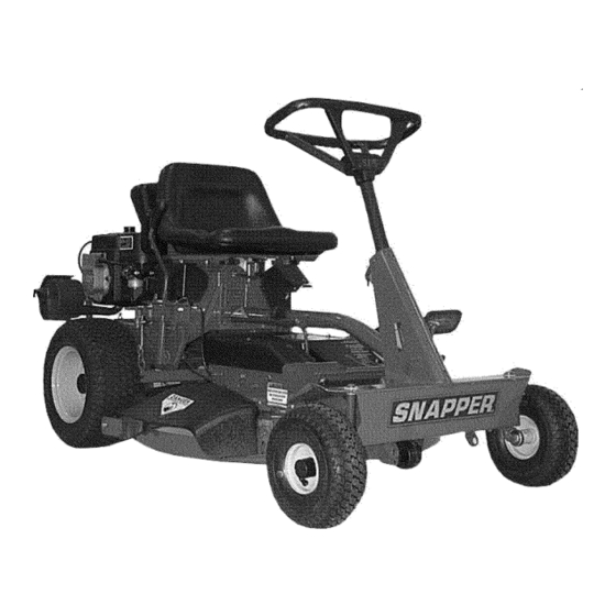
This manual has been prepared for the operator's of the The nomenclature drawing above, Figure 1.1, shows the SNAPPER Rear Engine Rider. Its purpose, aside from essential parts of the SNAPPER Rear Engine Rider. It is recommending standard operating procedures... -
Page 6: Pre-Start Checklist
Section 2 - OPERATING INSTRUCTIONS PRE-START CHECK LIST OPERATOR'S SEAT ADJUSTMENT Make the following checks and perform the service required before each start-up. 2.2.1. FRONT TO REAR ADJUSTMENT 2.1.1. Check tires and add or release air as needed 1. With the engine stopped, loosen the two adjusting to bring pressure to 12 psi in front and 12 psi in rear knobs and move seat to desired position. - Page 7 Section 2 - OPERATING INSTRUCTIONS STARTING & OPERATION TO START ENGINE, 2.3.1. ENGINE (ELECTRIC START) PUSH CLUTCH/BRAKE IMPORTANT: When the ignition key is turned to PEDAL ALL THE WAY "START", the engine will turn over, but will not start unless the Clutch/Brake pedal is pressed all the way DOWN down, the Blade Lever is in the "OFF"...
- Page 8 Section 2 - OPERATING INSTRUCTIONS STARTING & OPERATION 4. Open vent fuel filler turning 2.3.1. ENGINE (ELECTRIC START) (Continued) counterclockwise. NOTE: Failure to open vent on 8. Should the battery be too weak to start the engine, the fuel filler cap can cause engine to stall. refer to Section "ENGINE (MANUAL START)"...
- Page 9 3 seconds, the blade brake and hazards before and while backing. must be adjusted. Refer to Section "BLADE BRAKE ADJUSTMENT" for adjustment procedures or return machine an authorized SNAPPER dealer DEPRESS adjustment. DO NOT CONTINUE to operate machine PEDAL until blade brake...
- Page 10 3 seconds, the blade brake must be adjusted. Refer to Section "BLADE BRAKE ADJUSTMENT" for adjustment procedures or return machine an authorized SNAPPER dealer adjustment. DO NOT CONTINUE to operate machine until blade brake adjusted functioning properly.
-
Page 11: 2.5. Cutting Height Adjustment
Section 2 - OPERATING INSTRUCTIONS 2.5. CUTTING HEIGHT ADJUSTMENT STOPPING - ENGINE, WHEEL DRIVE, BLADE 2.4.4. PARK BRAKE 1. Adjust cutting height as desired to any one of five positions using deck lift lever. Move deck lift 1. Engage park brake by pushing clutch/brake pedal "DOWN"... -
Page 12: Reverse Lockout Mechanism
DO NOT operate machine if Reverse Lockout and while backing. Mechanism is not functioning properly. Contact your local Snapper dealer for assistance. We realize that this could cause a change to your previous mowing method but we encourage you to adjust to this new system. -
Page 13: Service -After First 5 Hours
INTRODUCTION require service. Refer to Engine Owner's Manual To retain the quality of the Rear Engine Rider, use for recommended service procedures. genuine SNAPPER replacement parts only. Contact a local SNAPPER dealer parts service 3.2.3. CHECK MOWER BLADE assistance. -
Page 14: 3.2.4. Check Blade Drive Belt
Refer to Section should be 1 1/4" but no less 1". If the measurement "BLADE BRAKE ADJUSTMENT" contact your is less than 1", the belt tension should be adjusted. SNAPPER dealer for assistance. Refer Section "BLADE DRIVE BELT ADJUSTMENT". 3.2.6. -
Page 15: Reverse Lockout Mechanism
"BATTERY WARNING REMOVAL". DO NOT operate machine if interlock system is not 2. Remove battery caps. Check fluid level. functioning properly, Contact your SNAPPER dealer I 3. Add water only to bring fluid to proper level - immediately for assistance, approximately 3/16"... -
Page 16: Front Wheel Bearing - Lubrication
Section 3 - MAINTENANCE LEFT REAR DO NOT attempt any adjustments, maintenance AXLE BEARING service with the engine or blades running. Stop GREASE blades. Stop engine. Engage parking brake. Remove FITTING key. Remove spark plug wires from spark plugs and (gas only) secure wires... -
Page 17: Service - Annually
Replace worn or damaged parts with genuine SNAPPER replacement parts available FILL/LEVEL from an authorized SNAPPER dealer. PLUG 3.5.1. All bushings and pivot areas. P.N, 1-1024 3.5.2. Check both front wheel king pins. 3.5.3. Transmission shift lever and detent. -
Page 18: Removing Fuel Tank
Section 3- MAINTENANCE REMOVING FUEL TANK Before removing fuel tank from rear engine rider, move rider outdoors where fumes can be easily dissipated. Removal of the tank is accomplished from the left side of the machine by pulling the tank straight up and away from the fuel tank bracket. -
Page 19: Section 4- Adjustments And Repair
SNAPPER dealer. WARNING ROTATE NUT CLOCKWISE Once blade is disengaged it should come to a stop in 3 INCREASE BRAKE TENSION, seconds or less. -
Page 20: Mower Deck Adjustment (Side To Side Levelness)
Section 4 - ADJUSTMENTS & REPAIR 7. Turn eccentric "UP" or "DOWN" as required until WARNING blade tips are within 1/8" of each other. See Figure 4.3. DO NOT attempt adjustments, maintenance, service or repairs with the engine running. STOP 8. -
Page 21: Mower Drive Belt Adjustment - 28" & 30" Decks
8. Reinstall the required amount of flat washers removed in step "5." and install hairpin. See Figure 4.6. Retain any remaining spacers for readjustment when a new belt is installed. IMPORTANT: SNAPPER Rear Engine Rider Models with 28" AND 30" decks... -
Page 22: 4.3 Rear Engine Rider Drive Components
If problems are experienced, contact your Snapper dealer for repair. 4.3.1 SERVICE BRAKE/PARK BRAKE ADJUSTMENT CABLE Test the wheel brake on a dry concrete surface. HOUSING When properly adjusted, the Rear Engine Rider will stop within 5 feet from fastest speed. -
Page 23: Mower Blade Replacement
Section 4 - ADJUSTMENTS & REPAIR 5. Inspect condition of blade. See Figure 4.11. WARNING 6. If blade is in good condition, sharpen at 22 to 28 DO NOT attempt adjustments, maintenance, degrees. DO NOT sharpen beyond existing cutting service or repairs with the engine running. - Page 24 Section 4 - ADJUSTMENTS & REPAIR 8. Route belt onto spindle pulley. Make sure belt is WARNING inside spindle belt guide and idler belt guide. Route belt DO NOT attempt adjustments, maintenance, as shown in Figure 4.15 or 4.16. service or repairs with the engine running.
- Page 25 Section 4 - ADJUSTMENTS & REPAIR WARNING RE D POSITIVE TERMINAL INSULATOR POSITIVE DO NOT attempt adjustments, maintenance, CABLE service or repairs with the engine running. Stop engine. Stop blade. Engage parking brake. Remove key. Remove spark plug wire from spark plug and BLACK secure away from plug.
- Page 26 Section 4 - ADJUSTMENTS & REPAIR WARNING lj , WARNING The electrolyte (acid) produces a highly explosive gas. DO NOT attempt to charge battery while installed on the I Keep all sparks, flame and fire away from area when Riding Mower. DO NOT use "BOOST" chargers on the charging battery or when...
-
Page 27: Accessories
1.120 11.90v 25% Charged One Ball Floating Less than 1.100 Less than 11.80v 0% Charged Zero Balls Floating SNAPPER REAR ENGINE RIDER ACCESSORIES PART NO. DESCRIPTION OF KIT MODELS USED ON 6-0517 ........ Wheel Weight (8" Wheels) ....... All Rear Engine Riders 6-0601 ...... -
Page 28: Troubleshooting
Engage park brake. Blown Fuse. Replace with new 20 AMP fuse. 7. Faulty interlock module. 7. Contact authorized SNAPPER dealer. 8. Ignition is in the OFF position. 8. Turn ignition switch to the START position. 9.Battery is weak or dead. - Page 29 2. Rubber drive disc is not tracking properly on Adjust rubber drive disc. drive disc. 3. Tapered axle bolt and nut missing. Replace with SNAPPER tapered bolt & nut. Contact authorized SNAPPER dealer. 4. Axle bearing seized. 5. Insufficient lubrication in chain case or Contact authorized SNAPPER dealer.
-
Page 30: Maintenance Schedule
MAINTENANCE SCHEDULE EACH EACH SUBJECT SERVICE REFERENCE HOURS HOURS HOURS HOURS SEASON TO BE PERFORMED PAGES Check Oil Level Engine Page 6 Engine Initial Oil Change Page 13 Engine Periodic Oil Change Page 15 Air Pre-Cleaner Service Sponge Pre- Engine Manual Cleaner Element Air Cleaner Replace Element... -
Page 31: Maintenance/Replacement Parts
MAINTENANCE/REPLACEMENT PARTS MAINTENANCE PARTS 2-2751 Engine Speed Control (Briggs Engine) 2-2483 Engine Speed Control (Kohler Engine) Clutch/Brake Cable 2-2449 Brake Cable 7-1909 3-5635 28" Cutter Blade IStandard - Not Air Lift Compatible) 1-9515 28" Cutter Blade (Standard - Air Lift Compatible) 1-6980 28"... -
Page 32: Warranty
For three (3) years from purchase date for the original purchaser's residential, non-commercial use, SNAPPER, through any authorized SNAPPER dealer will replace, free of charge (except for taxes where applicable), any part or parts found upon examination by the factory at McDonough, Georgia, to be defective in material or workmanship or both. -
Page 33: Primary Maintenance
PRIMARY MAINTENANCE ® illustration how dirt can & how maintenance can protect it! Snapper uses the best avail- able engines and components In their products in order to provide long, satisfactory service. However, proper care is essential In _" prolonging engine life. Dirt... - Page 34 Because of its working environ- ment, the air available to your Snapper engine Is " heavily saturated with air- borne dirt particles. As the dirt particles are stopped, Damage caused by a poorly serviced air...
- Page 35 PRIMARY MAINTENANCE Air Is also needed to keep your engine cool. Dirt, dust & debris build up to restrict and clog cooling air Intake screens and fins. Clean screens and fins at frequent Intervals. The engine blower housing and shrouds should be removed at least once each season or more often t under dry, dusty conditions...
- Page 36 2-cycle engine fuel, be sure the containers are clearly marked to avoid mix-up. Snapper 2-cycle engines require a 32 to 1 mixture of gasoline and BIA certified TC-W oil such as Snapper's 2-cycle engine o11. Many of the 2-cycle engine oils on the...
- Page 37 SERVICE NOTES...
-
Page 38: Important
Safety Instructions & Operator's Manual for REAR ENGINE RIDING MOWER SERIES 22 IMPORTANT Snapper products are built using engines that meet or exceed all applicable emissions requirements on the date manufactured. The labels on those engines contain very important emissions... -
Page 39: Section 2 - Operating Instructions
K - Kohler Engine Valve 33 -33" Cutting Deck 15 - 15.0 HP Engine Thank you for buying a SNAPPER Product! Before operating your machine, read this manual carefully and pay particular attention to the "IMPORTANT SAFETY INSTRUCTIONS" on Pages 2 & 3. Remember that all power... - Page 40 If you have any questions pertaining to your machine which your dealer cannot answer to your satisfaction, call or write the Customer Service Department at SNAPPER, McDonough, Georgia 30253. Phone: (1-800-935-2967). PROTECTION FOR CHILDREN...
- Page 41 10. Watch out for traffic when near or crossing 14. Have machine serviced authorized roadways. SNAPPER dealer at least once a year and have the 11. STOP engine immediately after striking dealer install any new safety devices. obstruction. Inspect machine repair 15.
-
Page 42: Starting & Stopping Engine, Blade & Wheel Drive
MAINTENANCE SCHEDULE ................MAINTENANCE/REPLACEMENT PARTS ............WARRANTY ..................... PRIMARY MAINTENANCE ................33-36 IMPORTANT: The figures and illustrations in this manual are provided for reference only and may differ from your specific model. Contact your Snapper dealer if you have questions. -
Page 43: Important Safety Instructions
This manual has been prepared for the operator's of the The nomenclature drawing above, Figure 1.1, shows the SNAPPER Rear Engine Rider. Its purpose, aside from essential parts of the SNAPPER Rear Engine Rider. It is recommending standard operating procedures... -
Page 44: Pre-Start Checklist
Section 2 - OPERATING INSTRUCTIONS PRE-START CHECK LIST OPERATOR'S SEAT ADJUSTMENT Make the following checks and perform the service required before each start-up. 2.2.1. FRONT TO REAR ADJUSTMENT 2.1.1. Check tires and add or release air as needed 1. With the engine stopped, loosen the two adjusting to bring pressure to 12 psi in front and 12 psi in rear knobs and move seat to desired position. -
Page 45: Parking Brake
Section 2 - OPERATING INSTRUCTIONS STARTING & OPERATION TO START ENGINE, 2.3.1. ENGINE (ELECTRIC START) PUSH CLUTCH/BRAKE IMPORTANT: When the ignition key is turned to PEDAL ALL THE WAY "START", the engine will turn over, but will not start unless the Clutch/Brake pedal is pressed all the way DOWN down, the Blade Lever is in the "OFF"... - Page 46 Section 2 - OPERATING INSTRUCTIONS STARTING & OPERATION 4. Open vent fuel filler turning 2.3.1. ENGINE (ELECTRIC START) (Continued) counterclockwise. NOTE: Failure to open vent on 8. Should the battery be too weak to start the engine, the fuel filler cap can cause engine to stall. refer to Section "ENGINE (MANUAL START)"...
- Page 47 3 seconds, the blade brake and hazards before and while backing. must be adjusted. Refer to Section "BLADE BRAKE ADJUSTMENT" for adjustment procedures or return machine an authorized SNAPPER dealer DEPRESS adjustment. DO NOT CONTINUE to operate machine PEDAL until blade brake...
- Page 48 3 seconds, the blade brake must be adjusted. Refer to Section "BLADE BRAKE ADJUSTMENT" for adjustment procedures or return machine an authorized SNAPPER dealer adjustment. DO NOT CONTINUE to operate machine until blade brake adjusted functioning properly.
-
Page 49: 2.5. Cutting Height Adjustment
Section 2 - OPERATING INSTRUCTIONS 2.5. CUTTING HEIGHT ADJUSTMENT STOPPING - ENGINE, WHEEL DRIVE, BLADE 2.4.4. PARK BRAKE 1. Adjust cutting height as desired to any one of five positions using deck lift lever. Move deck lift 1. Engage park brake by pushing clutch/brake pedal "DOWN"... -
Page 50: Reverse Lockout Mechanism
DO NOT operate machine if Reverse Lockout and while backing. Mechanism is not functioning properly. Contact your local Snapper dealer for assistance. We realize that this could cause a change to your previous mowing method but we encourage you to adjust to this new system. -
Page 51: Service -After First 5 Hours
INTRODUCTION require service. Refer to Engine Owner's Manual To retain the quality of the Rear Engine Rider, use for recommended service procedures. genuine SNAPPER replacement parts only. Contact a local SNAPPER dealer parts service 3.2.3. CHECK MOWER BLADE assistance. -
Page 52: 3.2.4. Check Blade Drive Belt
Refer to Section should be 1 1/4" but no less 1". If the measurement "BLADE BRAKE ADJUSTMENT" contact your is less than 1", the belt tension should be adjusted. SNAPPER dealer for assistance. Refer Section "BLADE DRIVE BELT ADJUSTMENT". 3.2.6. -
Page 53: Reverse Lockout Mechanism
"BATTERY WARNING REMOVAL". DO NOT operate machine if interlock system is not 2. Remove battery caps. Check fluid level. functioning properly, Contact your SNAPPER dealer I 3. Add water only to bring fluid to proper level - immediately for assistance, approximately 3/16"... -
Page 54: Front Wheel Bearing - Lubrication
Section 3 - MAINTENANCE LEFT REAR DO NOT attempt any adjustments, maintenance AXLE BEARING service with the engine or blades running. Stop GREASE blades. Stop engine. Engage parking brake. Remove FITTING key. Remove spark plug wires from spark plugs and (gas only) secure wires... -
Page 55: Service - Annually
Replace worn or damaged parts with genuine SNAPPER replacement parts available FILL/LEVEL from an authorized SNAPPER dealer. PLUG 3.5.1. All bushings and pivot areas. P.N, 1-1024 3.5.2. Check both front wheel king pins. 3.5.3. Transmission shift lever and detent. -
Page 56: Removing Fuel Tank
Section 3- MAINTENANCE REMOVING FUEL TANK Before removing fuel tank from rear engine rider, move rider outdoors where fumes can be easily dissipated. Removal of the tank is accomplished from the left side of the machine by pulling the tank straight up and away from the fuel tank bracket. -
Page 57: Section 4- Adjustments And Repair
SNAPPER dealer. WARNING ROTATE NUT CLOCKWISE Once blade is disengaged it should come to a stop in 3 INCREASE BRAKE TENSION, seconds or less. -
Page 58: Mower Deck Adjustment (Side To Side Levelness)
Section 4 - ADJUSTMENTS & REPAIR 7. Turn eccentric "UP" or "DOWN" as required until WARNING blade tips are within 1/8" of each other. See Figure 4.3. DO NOT attempt adjustments, maintenance, service or repairs with the engine running. STOP 8. -
Page 59: Mower Drive Belt Adjustment - 28" & 30" Decks
8. Reinstall the required amount of flat washers removed in step "5." and install hairpin. See Figure 4.6. Retain any remaining spacers for readjustment when a new belt is installed. IMPORTANT: SNAPPER Rear Engine Rider Models with 28" AND 30" decks... -
Page 60: 4.3 Rear Engine Rider Drive Components
If problems are experienced, contact your Snapper dealer for repair. 4.3.1 SERVICE BRAKE/PARK BRAKE ADJUSTMENT CABLE Test the wheel brake on a dry concrete surface. HOUSING When properly adjusted, the Rear Engine Rider will stop within 5 feet from fastest speed. -
Page 61: Mower Blade Replacement
Section 4 - ADJUSTMENTS & REPAIR 5. Inspect condition of blade. See Figure 4.11. WARNING 6. If blade is in good condition, sharpen at 22 to 28 DO NOT attempt adjustments, maintenance, degrees. DO NOT sharpen beyond existing cutting service or repairs with the engine running. - Page 62 Section 4 - ADJUSTMENTS & REPAIR 8. Route belt onto spindle pulley. Make sure belt is WARNING inside spindle belt guide and idler belt guide. Route belt DO NOT attempt adjustments, maintenance, as shown in Figure 4.15 or 4.16. service or repairs with the engine running.
- Page 63 Section 4 - ADJUSTMENTS & REPAIR WARNING RE D POSITIVE TERMINAL INSULATOR POSITIVE DO NOT attempt adjustments, maintenance, CABLE service or repairs with the engine running. Stop engine. Stop blade. Engage parking brake. Remove key. Remove spark plug wire from spark plug and BLACK secure away from plug.
- Page 64 Section 4 - ADJUSTMENTS & REPAIR WARNING lj , WARNING The electrolyte (acid) produces a highly explosive gas. DO NOT attempt to charge battery while installed on the I Keep all sparks, flame and fire away from area when Riding Mower. DO NOT use "BOOST" chargers on the charging battery or when...
-
Page 65: Accessories
1.120 11.90v 25% Charged One Ball Floating Less than 1.100 Less than 11.80v 0% Charged Zero Balls Floating SNAPPER REAR ENGINE RIDER ACCESSORIES PART NO. DESCRIPTION OF KIT MODELS USED ON 6-0517 ........ Wheel Weight (8" Wheels) ....... All Rear Engine Riders 6-0601 ...... -
Page 66: Troubleshooting
Engage park brake. Blown Fuse. Replace with new 20 AMP fuse. 7. Faulty interlock module. 7. Contact authorized SNAPPER dealer. 8. Ignition is in the OFF position. 8. Turn ignition switch to the START position. 9.Battery is weak or dead. - Page 67 2. Rubber drive disc is not tracking properly on Adjust rubber drive disc. drive disc. 3. Tapered axle bolt and nut missing. Replace with SNAPPER tapered bolt & nut. Contact authorized SNAPPER dealer. 4. Axle bearing seized. 5. Insufficient lubrication in chain case or Contact authorized SNAPPER dealer.
-
Page 68: Maintenance Schedule
MAINTENANCE SCHEDULE EACH EACH SUBJECT SERVICE REFERENCE HOURS HOURS HOURS HOURS SEASON TO BE PERFORMED PAGES Check Oil Level Engine Page 6 Engine Initial Oil Change Page 13 Engine Periodic Oil Change Page 15 Air Pre-Cleaner Service Sponge Pre- Engine Manual Cleaner Element Air Cleaner Replace Element... -
Page 69: Maintenance/Replacement Parts
MAINTENANCE/REPLACEMENT PARTS MAINTENANCE PARTS 2-2751 Engine Speed Control (Briggs Engine) 2-2483 Engine Speed Control (Kohler Engine) Clutch/Brake Cable 2-2449 Brake Cable 7-1909 3-5635 28" Cutter Blade IStandard - Not Air Lift Compatible) 1-9515 28" Cutter Blade (Standard - Air Lift Compatible) 1-6980 28"... -
Page 70: Warranty
For three (3) years from purchase date for the original purchaser's residential, non-commercial use, SNAPPER, through any authorized SNAPPER dealer will replace, free of charge (except for taxes where applicable), any part or parts found upon examination by the factory at McDonough, Georgia, to be defective in material or workmanship or both. -
Page 71: Primary Maintenance
PRIMARY MAINTENANCE ® illustration how dirt can & how maintenance can protect it! Snapper uses the best avail- able engines and components In their products in order to provide long, satisfactory service. However, proper care is essential In _" prolonging engine life. Dirt... -
Page 72: Primary Maintenance
Because of its working environ- ment, the air available to your Snapper engine Is " heavily saturated with air- borne dirt particles. As the dirt particles are stopped, Damage caused by a poorly serviced air... - Page 73 PRIMARY MAINTENANCE Air Is also needed to keep your engine cool. Dirt, dust & debris build up to restrict and clog cooling air Intake screens and fins. Clean screens and fins at frequent Intervals. The engine blower housing and shrouds should be removed at least once each season or more often t under dry, dusty conditions...
- Page 74 2-cycle engine fuel, be sure the containers are clearly marked to avoid mix-up. Snapper 2-cycle engines require a 32 to 1 mixture of gasoline and BIA certified TC-W oil such as Snapper's 2-cycle engine o11. Many of the 2-cycle engine oils on the...
- Page 75 SERVICE NOTES...
-
Page 76: Important
Safety Instructions & Operator's Manual for REAR ENGINE RIDING MOWER SERIES 22 IMPORTANT Snapper products are built using engines that meet or exceed all applicable emissions requirements on the date manufactured. The labels on those engines contain very important emissions... - Page 77 K - Kohler Engine Valve 33 -33" Cutting Deck 15 - 15.0 HP Engine Thank you for buying a SNAPPER Product! Before operating your machine, read this manual carefully and pay particular attention to the "IMPORTANT SAFETY INSTRUCTIONS" on Pages 2 & 3. Remember that all power...
- Page 78 If you have any questions pertaining to your machine which your dealer cannot answer to your satisfaction, call or write the Customer Service Department at SNAPPER, McDonough, Georgia 30253. Phone: (1-800-935-2967). PROTECTION FOR CHILDREN...
- Page 79 10. Watch out for traffic when near or crossing 14. Have machine serviced authorized roadways. SNAPPER dealer at least once a year and have the 11. STOP engine immediately after striking dealer install any new safety devices. obstruction. Inspect machine repair 15.
- Page 80 MAINTENANCE SCHEDULE ................MAINTENANCE/REPLACEMENT PARTS ............WARRANTY ..................... PRIMARY MAINTENANCE ................33-36 IMPORTANT: The figures and illustrations in this manual are provided for reference only and may differ from your specific model. Contact your Snapper dealer if you have questions.
-
Page 81: Important Safety Instructions
This manual has been prepared for the operator's of the The nomenclature drawing above, Figure 1.1, shows the SNAPPER Rear Engine Rider. Its purpose, aside from essential parts of the SNAPPER Rear Engine Rider. It is recommending standard operating procedures... -
Page 82: Pre-Start Checklist
Section 2 - OPERATING INSTRUCTIONS PRE-START CHECK LIST OPERATOR'S SEAT ADJUSTMENT Make the following checks and perform the service required before each start-up. 2.2.1. FRONT TO REAR ADJUSTMENT 2.1.1. Check tires and add or release air as needed 1. With the engine stopped, loosen the two adjusting to bring pressure to 12 psi in front and 12 psi in rear knobs and move seat to desired position. -
Page 83: Parking Brake
Section 2 - OPERATING INSTRUCTIONS STARTING & OPERATION TO START ENGINE, 2.3.1. ENGINE (ELECTRIC START) PUSH CLUTCH/BRAKE IMPORTANT: When the ignition key is turned to PEDAL ALL THE WAY "START", the engine will turn over, but will not start unless the Clutch/Brake pedal is pressed all the way DOWN down, the Blade Lever is in the "OFF"... - Page 84 Section 2 - OPERATING INSTRUCTIONS STARTING & OPERATION 4. Open vent fuel filler turning 2.3.1. ENGINE (ELECTRIC START) (Continued) counterclockwise. NOTE: Failure to open vent on 8. Should the battery be too weak to start the engine, the fuel filler cap can cause engine to stall. refer to Section "ENGINE (MANUAL START)"...
- Page 85 3 seconds, the blade brake and hazards before and while backing. must be adjusted. Refer to Section "BLADE BRAKE ADJUSTMENT" for adjustment procedures or return machine an authorized SNAPPER dealer DEPRESS adjustment. DO NOT CONTINUE to operate machine PEDAL until blade brake...
- Page 86 3 seconds, the blade brake must be adjusted. Refer to Section "BLADE BRAKE ADJUSTMENT" for adjustment procedures or return machine an authorized SNAPPER dealer adjustment. DO NOT CONTINUE to operate machine until blade brake adjusted functioning properly.
-
Page 87: 2.5. Cutting Height Adjustment
Section 2 - OPERATING INSTRUCTIONS 2.5. CUTTING HEIGHT ADJUSTMENT STOPPING - ENGINE, WHEEL DRIVE, BLADE 2.4.4. PARK BRAKE 1. Adjust cutting height as desired to any one of five positions using deck lift lever. Move deck lift 1. Engage park brake by pushing clutch/brake pedal "DOWN"... -
Page 88: Reverse Lockout Mechanism
DO NOT operate machine if Reverse Lockout and while backing. Mechanism is not functioning properly. Contact your local Snapper dealer for assistance. We realize that this could cause a change to your previous mowing method but we encourage you to adjust to this new system. -
Page 89: Service -After First 5 Hours
INTRODUCTION require service. Refer to Engine Owner's Manual To retain the quality of the Rear Engine Rider, use for recommended service procedures. genuine SNAPPER replacement parts only. Contact a local SNAPPER dealer parts service 3.2.3. CHECK MOWER BLADE assistance. -
Page 90: 3.2.4. Check Blade Drive Belt
Refer to Section should be 1 1/4" but no less 1". If the measurement "BLADE BRAKE ADJUSTMENT" contact your is less than 1", the belt tension should be adjusted. SNAPPER dealer for assistance. Refer Section "BLADE DRIVE BELT ADJUSTMENT". 3.2.6. -
Page 91: Reverse Lockout Mechanism
"BATTERY WARNING REMOVAL". DO NOT operate machine if interlock system is not 2. Remove battery caps. Check fluid level. functioning properly, Contact your SNAPPER dealer I 3. Add water only to bring fluid to proper level - immediately for assistance, approximately 3/16"... -
Page 92: Front Wheel Bearing - Lubrication
Section 3 - MAINTENANCE LEFT REAR DO NOT attempt any adjustments, maintenance AXLE BEARING service with the engine or blades running. Stop GREASE blades. Stop engine. Engage parking brake. Remove FITTING key. Remove spark plug wires from spark plugs and (gas only) secure wires... -
Page 93: Service - Annually
Replace worn or damaged parts with genuine SNAPPER replacement parts available FILL/LEVEL from an authorized SNAPPER dealer. PLUG 3.5.1. All bushings and pivot areas. P.N, 1-1024 3.5.2. Check both front wheel king pins. 3.5.3. Transmission shift lever and detent. -
Page 94: Removing Fuel Tank
Section 3- MAINTENANCE REMOVING FUEL TANK Before removing fuel tank from rear engine rider, move rider outdoors where fumes can be easily dissipated. Removal of the tank is accomplished from the left side of the machine by pulling the tank straight up and away from the fuel tank bracket. -
Page 95: Section 4- Adjustments And Repair
SNAPPER dealer. WARNING ROTATE NUT CLOCKWISE Once blade is disengaged it should come to a stop in 3 INCREASE BRAKE TENSION, seconds or less. -
Page 96: Mower Deck Adjustment (Side To Side Levelness)
Section 4 - ADJUSTMENTS & REPAIR 7. Turn eccentric "UP" or "DOWN" as required until WARNING blade tips are within 1/8" of each other. See Figure 4.3. DO NOT attempt adjustments, maintenance, service or repairs with the engine running. STOP 8. -
Page 97: Mower Drive Belt Adjustment - 28" & 30" Decks
8. Reinstall the required amount of flat washers removed in step "5." and install hairpin. See Figure 4.6. Retain any remaining spacers for readjustment when a new belt is installed. IMPORTANT: SNAPPER Rear Engine Rider Models with 28" AND 30" decks... -
Page 98: 4.3 Rear Engine Rider Drive Components
If problems are experienced, contact your Snapper dealer for repair. 4.3.1 SERVICE BRAKE/PARK BRAKE ADJUSTMENT CABLE Test the wheel brake on a dry concrete surface. HOUSING When properly adjusted, the Rear Engine Rider will stop within 5 feet from fastest speed. -
Page 99: Mower Blade Replacement
Section 4 - ADJUSTMENTS & REPAIR 5. Inspect condition of blade. See Figure 4.11. WARNING 6. If blade is in good condition, sharpen at 22 to 28 DO NOT attempt adjustments, maintenance, degrees. DO NOT sharpen beyond existing cutting service or repairs with the engine running. - Page 100 Section 4 - ADJUSTMENTS & REPAIR 8. Route belt onto spindle pulley. Make sure belt is WARNING inside spindle belt guide and idler belt guide. Route belt DO NOT attempt adjustments, maintenance, as shown in Figure 4.15 or 4.16. service or repairs with the engine running.
- Page 101 Section 4 - ADJUSTMENTS & REPAIR WARNING RE D POSITIVE TERMINAL INSULATOR POSITIVE DO NOT attempt adjustments, maintenance, CABLE service or repairs with the engine running. Stop engine. Stop blade. Engage parking brake. Remove key. Remove spark plug wire from spark plug and BLACK secure away from plug.
- Page 102 Section 4 - ADJUSTMENTS & REPAIR WARNING lj , WARNING The electrolyte (acid) produces a highly explosive gas. DO NOT attempt to charge battery while installed on the I Keep all sparks, flame and fire away from area when Riding Mower. DO NOT use "BOOST" chargers on the charging battery or when...
-
Page 103: Accessories
1.120 11.90v 25% Charged One Ball Floating Less than 1.100 Less than 11.80v 0% Charged Zero Balls Floating SNAPPER REAR ENGINE RIDER ACCESSORIES PART NO. DESCRIPTION OF KIT MODELS USED ON 6-0517 ........ Wheel Weight (8" Wheels) ....... All Rear Engine Riders 6-0601 ...... -
Page 104: Troubleshooting
Engage park brake. Blown Fuse. Replace with new 20 AMP fuse. 7. Faulty interlock module. 7. Contact authorized SNAPPER dealer. 8. Ignition is in the OFF position. 8. Turn ignition switch to the START position. 9.Battery is weak or dead. - Page 105 2. Rubber drive disc is not tracking properly on Adjust rubber drive disc. drive disc. 3. Tapered axle bolt and nut missing. Replace with SNAPPER tapered bolt & nut. Contact authorized SNAPPER dealer. 4. Axle bearing seized. 5. Insufficient lubrication in chain case or Contact authorized SNAPPER dealer.
-
Page 106: Maintenance Schedule
MAINTENANCE SCHEDULE EACH EACH SUBJECT SERVICE REFERENCE HOURS HOURS HOURS HOURS SEASON TO BE PERFORMED PAGES Check Oil Level Engine Page 6 Engine Initial Oil Change Page 13 Engine Periodic Oil Change Page 15 Air Pre-Cleaner Service Sponge Pre- Engine Manual Cleaner Element Air Cleaner Replace Element... -
Page 107: Maintenance/Replacement Parts
MAINTENANCE/REPLACEMENT PARTS MAINTENANCE PARTS 2-2751 Engine Speed Control (Briggs Engine) 2-2483 Engine Speed Control (Kohler Engine) Clutch/Brake Cable 2-2449 Brake Cable 7-1909 3-5635 28" Cutter Blade IStandard - Not Air Lift Compatible) 1-9515 28" Cutter Blade (Standard - Air Lift Compatible) 1-6980 28"... -
Page 108: Warranty
For three (3) years from purchase date for the original purchaser's residential, non-commercial use, SNAPPER, through any authorized SNAPPER dealer will replace, free of charge (except for taxes where applicable), any part or parts found upon examination by the factory at McDonough, Georgia, to be defective in material or workmanship or both. -
Page 109: Primary Maintenance
PRIMARY MAINTENANCE ® illustration how dirt can & how maintenance can protect it! Snapper uses the best avail- able engines and components In their products in order to provide long, satisfactory service. However, proper care is essential In _" prolonging engine life. Dirt... -
Page 110: Primary Maintenance
Because of its working environ- ment, the air available to your Snapper engine Is " heavily saturated with air- borne dirt particles. As the dirt particles are stopped, Damage caused by a poorly serviced air... - Page 111 PRIMARY MAINTENANCE Air Is also needed to keep your engine cool. Dirt, dust & debris build up to restrict and clog cooling air Intake screens and fins. Clean screens and fins at frequent Intervals. The engine blower housing and shrouds should be removed at least once each season or more often t under dry, dusty conditions...
- Page 112 2-cycle engine fuel, be sure the containers are clearly marked to avoid mix-up. Snapper 2-cycle engines require a 32 to 1 mixture of gasoline and BIA certified TC-W oil such as Snapper's 2-cycle engine o11. Many of the 2-cycle engine oils on the...
- Page 113 SERVICE NOTES...
-
Page 114: Important
Safety Instructions & Operator's Manual for REAR ENGINE RIDING MOWER SERIES 22 IMPORTANT Snapper products are built using engines that meet or exceed all applicable emissions requirements on the date manufactured. The labels on those engines contain very important emissions... - Page 115 K - Kohler Engine Valve 33 -33" Cutting Deck 15 - 15.0 HP Engine Thank you for buying a SNAPPER Product! Before operating your machine, read this manual carefully and pay particular attention to the "IMPORTANT SAFETY INSTRUCTIONS" on Pages 2 & 3. Remember that all power...
- Page 116 If you have any questions pertaining to your machine which your dealer cannot answer to your satisfaction, call or write the Customer Service Department at SNAPPER, McDonough, Georgia 30253. Phone: (1-800-935-2967). PROTECTION FOR CHILDREN...
- Page 117 10. Watch out for traffic when near or crossing 14. Have machine serviced authorized roadways. SNAPPER dealer at least once a year and have the 11. STOP engine immediately after striking dealer install any new safety devices. obstruction. Inspect machine repair 15.
- Page 118 MAINTENANCE SCHEDULE ................MAINTENANCE/REPLACEMENT PARTS ............WARRANTY ..................... PRIMARY MAINTENANCE ................33-36 IMPORTANT: The figures and illustrations in this manual are provided for reference only and may differ from your specific model. Contact your Snapper dealer if you have questions.
-
Page 119: Important Safety Instructions
This manual has been prepared for the operator's of the The nomenclature drawing above, Figure 1.1, shows the SNAPPER Rear Engine Rider. Its purpose, aside from essential parts of the SNAPPER Rear Engine Rider. It is recommending standard operating procedures... -
Page 120: Pre-Start Checklist
Section 2 - OPERATING INSTRUCTIONS PRE-START CHECK LIST OPERATOR'S SEAT ADJUSTMENT Make the following checks and perform the service required before each start-up. 2.2.1. FRONT TO REAR ADJUSTMENT 2.1.1. Check tires and add or release air as needed 1. With the engine stopped, loosen the two adjusting to bring pressure to 12 psi in front and 12 psi in rear knobs and move seat to desired position. -
Page 121: Parking Brake
Section 2 - OPERATING INSTRUCTIONS STARTING & OPERATION TO START ENGINE, 2.3.1. ENGINE (ELECTRIC START) PUSH CLUTCH/BRAKE IMPORTANT: When the ignition key is turned to PEDAL ALL THE WAY "START", the engine will turn over, but will not start unless the Clutch/Brake pedal is pressed all the way DOWN down, the Blade Lever is in the "OFF"... - Page 122 Section 2 - OPERATING INSTRUCTIONS STARTING & OPERATION 4. Open vent fuel filler turning 2.3.1. ENGINE (ELECTRIC START) (Continued) counterclockwise. NOTE: Failure to open vent on 8. Should the battery be too weak to start the engine, the fuel filler cap can cause engine to stall. refer to Section "ENGINE (MANUAL START)"...
- Page 123 3 seconds, the blade brake and hazards before and while backing. must be adjusted. Refer to Section "BLADE BRAKE ADJUSTMENT" for adjustment procedures or return machine an authorized SNAPPER dealer DEPRESS adjustment. DO NOT CONTINUE to operate machine PEDAL until blade brake...
- Page 124 3 seconds, the blade brake must be adjusted. Refer to Section "BLADE BRAKE ADJUSTMENT" for adjustment procedures or return machine an authorized SNAPPER dealer adjustment. DO NOT CONTINUE to operate machine until blade brake adjusted functioning properly.
-
Page 125: 2.5. Cutting Height Adjustment
Section 2 - OPERATING INSTRUCTIONS 2.5. CUTTING HEIGHT ADJUSTMENT STOPPING - ENGINE, WHEEL DRIVE, BLADE 2.4.4. PARK BRAKE 1. Adjust cutting height as desired to any one of five positions using deck lift lever. Move deck lift 1. Engage park brake by pushing clutch/brake pedal "DOWN"... -
Page 126: Reverse Lockout Mechanism
DO NOT operate machine if Reverse Lockout and while backing. Mechanism is not functioning properly. Contact your local Snapper dealer for assistance. We realize that this could cause a change to your previous mowing method but we encourage you to adjust to this new system. -
Page 127: Service -After First 5 Hours
INTRODUCTION require service. Refer to Engine Owner's Manual To retain the quality of the Rear Engine Rider, use for recommended service procedures. genuine SNAPPER replacement parts only. Contact a local SNAPPER dealer parts service 3.2.3. CHECK MOWER BLADE assistance. -
Page 128: 3.2.4. Check Blade Drive Belt
Refer to Section should be 1 1/4" but no less 1". If the measurement "BLADE BRAKE ADJUSTMENT" contact your is less than 1", the belt tension should be adjusted. SNAPPER dealer for assistance. Refer Section "BLADE DRIVE BELT ADJUSTMENT". 3.2.6. -
Page 129: Reverse Lockout Mechanism
"BATTERY WARNING REMOVAL". DO NOT operate machine if interlock system is not 2. Remove battery caps. Check fluid level. functioning properly, Contact your SNAPPER dealer I 3. Add water only to bring fluid to proper level - immediately for assistance, approximately 3/16"... -
Page 130: Front Wheel Bearing - Lubrication
Section 3 - MAINTENANCE LEFT REAR DO NOT attempt any adjustments, maintenance AXLE BEARING service with the engine or blades running. Stop GREASE blades. Stop engine. Engage parking brake. Remove FITTING key. Remove spark plug wires from spark plugs and (gas only) secure wires... -
Page 131: Service - Annually
Replace worn or damaged parts with genuine SNAPPER replacement parts available FILL/LEVEL from an authorized SNAPPER dealer. PLUG 3.5.1. All bushings and pivot areas. P.N, 1-1024 3.5.2. Check both front wheel king pins. 3.5.3. Transmission shift lever and detent. -
Page 132: Removing Fuel Tank
Section 3- MAINTENANCE REMOVING FUEL TANK Before removing fuel tank from rear engine rider, move rider outdoors where fumes can be easily dissipated. Removal of the tank is accomplished from the left side of the machine by pulling the tank straight up and away from the fuel tank bracket. -
Page 133: Section 4- Adjustments And Repair
SNAPPER dealer. WARNING ROTATE NUT CLOCKWISE Once blade is disengaged it should come to a stop in 3 INCREASE BRAKE TENSION, seconds or less. -
Page 134: Mower Deck Adjustment (Side To Side Levelness)
Section 4 - ADJUSTMENTS & REPAIR 7. Turn eccentric "UP" or "DOWN" as required until WARNING blade tips are within 1/8" of each other. See Figure 4.3. DO NOT attempt adjustments, maintenance, service or repairs with the engine running. STOP 8. -
Page 135: Mower Drive Belt Adjustment - 28" & 30" Decks
8. Reinstall the required amount of flat washers removed in step "5." and install hairpin. See Figure 4.6. Retain any remaining spacers for readjustment when a new belt is installed. IMPORTANT: SNAPPER Rear Engine Rider Models with 28" AND 30" decks... -
Page 136: 4.3 Rear Engine Rider Drive Components
If problems are experienced, contact your Snapper dealer for repair. 4.3.1 SERVICE BRAKE/PARK BRAKE ADJUSTMENT CABLE Test the wheel brake on a dry concrete surface. HOUSING When properly adjusted, the Rear Engine Rider will stop within 5 feet from fastest speed. -
Page 137: Mower Blade Replacement
Section 4 - ADJUSTMENTS & REPAIR 5. Inspect condition of blade. See Figure 4.11. WARNING 6. If blade is in good condition, sharpen at 22 to 28 DO NOT attempt adjustments, maintenance, degrees. DO NOT sharpen beyond existing cutting service or repairs with the engine running. - Page 138 Section 4 - ADJUSTMENTS & REPAIR 8. Route belt onto spindle pulley. Make sure belt is WARNING inside spindle belt guide and idler belt guide. Route belt DO NOT attempt adjustments, maintenance, as shown in Figure 4.15 or 4.16. service or repairs with the engine running.
- Page 139 Section 4 - ADJUSTMENTS & REPAIR WARNING RE D POSITIVE TERMINAL INSULATOR POSITIVE DO NOT attempt adjustments, maintenance, CABLE service or repairs with the engine running. Stop engine. Stop blade. Engage parking brake. Remove key. Remove spark plug wire from spark plug and BLACK secure away from plug.
- Page 140 Section 4 - ADJUSTMENTS & REPAIR WARNING lj , WARNING The electrolyte (acid) produces a highly explosive gas. DO NOT attempt to charge battery while installed on the I Keep all sparks, flame and fire away from area when Riding Mower. DO NOT use "BOOST" chargers on the charging battery or when...
-
Page 141: Accessories
1.120 11.90v 25% Charged One Ball Floating Less than 1.100 Less than 11.80v 0% Charged Zero Balls Floating SNAPPER REAR ENGINE RIDER ACCESSORIES PART NO. DESCRIPTION OF KIT MODELS USED ON 6-0517 ........ Wheel Weight (8" Wheels) ....... All Rear Engine Riders 6-0601 ...... -
Page 142: Troubleshooting
Engage park brake. Blown Fuse. Replace with new 20 AMP fuse. 7. Faulty interlock module. 7. Contact authorized SNAPPER dealer. 8. Ignition is in the OFF position. 8. Turn ignition switch to the START position. 9.Battery is weak or dead. - Page 143 2. Rubber drive disc is not tracking properly on Adjust rubber drive disc. drive disc. 3. Tapered axle bolt and nut missing. Replace with SNAPPER tapered bolt & nut. Contact authorized SNAPPER dealer. 4. Axle bearing seized. 5. Insufficient lubrication in chain case or Contact authorized SNAPPER dealer.
-
Page 144: Maintenance Schedule
MAINTENANCE SCHEDULE EACH EACH SUBJECT SERVICE REFERENCE HOURS HOURS HOURS HOURS SEASON TO BE PERFORMED PAGES Check Oil Level Engine Page 6 Engine Initial Oil Change Page 13 Engine Periodic Oil Change Page 15 Air Pre-Cleaner Service Sponge Pre- Engine Manual Cleaner Element Air Cleaner Replace Element... -
Page 145: Maintenance/Replacement Parts
MAINTENANCE/REPLACEMENT PARTS MAINTENANCE PARTS 2-2751 Engine Speed Control (Briggs Engine) 2-2483 Engine Speed Control (Kohler Engine) Clutch/Brake Cable 2-2449 Brake Cable 7-1909 3-5635 28" Cutter Blade IStandard - Not Air Lift Compatible) 1-9515 28" Cutter Blade (Standard - Air Lift Compatible) 1-6980 28"... -
Page 146: Warranty
For three (3) years from purchase date for the original purchaser's residential, non-commercial use, SNAPPER, through any authorized SNAPPER dealer will replace, free of charge (except for taxes where applicable), any part or parts found upon examination by the factory at McDonough, Georgia, to be defective in material or workmanship or both. -
Page 147: Primary Maintenance
PRIMARY MAINTENANCE ® illustration how dirt can & how maintenance can protect it! Snapper uses the best avail- able engines and components In their products in order to provide long, satisfactory service. However, proper care is essential In _" prolonging engine life. Dirt... - Page 148 Because of its working environ- ment, the air available to your Snapper engine Is " heavily saturated with air- borne dirt particles. As the dirt particles are stopped, Damage caused by a poorly serviced air...
- Page 149 PRIMARY MAINTENANCE Air Is also needed to keep your engine cool. Dirt, dust & debris build up to restrict and clog cooling air Intake screens and fins. Clean screens and fins at frequent Intervals. The engine blower housing and shrouds should be removed at least once each season or more often t under dry, dusty conditions...
- Page 150 2-cycle engine fuel, be sure the containers are clearly marked to avoid mix-up. Snapper 2-cycle engines require a 32 to 1 mixture of gasoline and BIA certified TC-W oil such as Snapper's 2-cycle engine o11. Many of the 2-cycle engine oils on the...
- Page 151 SERVICE NOTES...
-
Page 152: Important
Safety Instructions & Operator's Manual for REAR ENGINE RIDING MOWER SERIES 22 IMPORTANT Snapper products are built using engines that meet or exceed all applicable emissions requirements on the date manufactured. The labels on those engines contain very important emissions...
Need help?
Do you have a question about the 301222BE SERIES 22 and is the answer not in the manual?
Questions and answers