Poulan Pro PR524 Owner's Manual
Walk-behind snow throwers
Hide thumbs
Also See for PR524:
- Owner's manual (32 pages) ,
- Owner's manual (32 pages) ,
- Owner's manual (36 pages)
Table of Contents
Advertisement
Quick Links
Advertisement
Table of Contents

Subscribe to Our Youtube Channel
Related Manuals for Poulan Pro PR524


Summary of Contents for Poulan Pro PR524
- Page 1 IMPORTANT MANUAL Do Not Throw Away OWNER'S MANUAL MODEL NUMBER: WARNING: PR524 Read the Owner's Manual follow all Warnings and Safety Instructions. Failure to do so SNOW THROWER can result in serious injury. 199350 Rev. 3 06.02.06 Always Wear Eye Protection...
-
Page 2: Safety Rules
IMPORTANT Safe Operation Practices for Walk-Behind Snow Throwers This snow thrower is capable of amputating hands and feet and throwing objects, Failure to observe the following safety instructions could result in serious injury. WARNING: Snow throwers have ex- Look for this symbol to point out im- &... -
Page 3: Table Of Contents
6, When cleaning, repairing orinspecting thesnowthrower, 16,Never t ouch a hotengine ormuffler, stop theengine andmake certain thecollector/impeller andall moving partshavestopped, D isconnect the Clearing a Clogged Discharge Chute spark plugwireandkeep thewireaway fromtheplug Hand contact with the rotating impeller inside the discharge toprevent someone f romaccidentally starting theen- chute is the most common cause of injury associated with gine. -
Page 4: Assembly / Pre-Operation
PARTS PACKED SEPARATELY IN CARTON (1) AUGER CONTROL ROD (1)TRACTION DRIVECONTROLROD (1)MULTI= WRENCH O)DIS= CHARGE CHUTE (3) RETAINER ROTATER HEAD MOUNTING SPRINGS (1)WASHER 3/8 (1) LOCKNUT 3/8 (2) SAFETY iGNiTiON KEYS EXTRA SHEAR BOLTS AND HUTS © (4) SHOULDERBOLTS (8) LOCKNUTS (4) CAPSCREWS 1!4=20 1/4=20x 2 (AUGERSHAFT) - Page 5 ASSEMBLY / PRE-OPERATION INSTALL TRACTION DRIVE CONTROL ROD NOTE: The multi-wrench may be used for assembly of the chute rotator head to snow thrower and making adjustments (See Figs. 3 and 4) to the skid plates. The traction drive control rod has the long loop on the end UNFOLD UPPER HANDLE of the spring as shown.
- Page 6 ASSEMBLY / PRE-OPERATION INSTALL DISCHARGE CHUTE / CHUTE ROTATER INSTALL AUGER CONTROL ROD (See Figs. 5 and 6) HEAD (See Fig. 7) The auger control rod has the short loop on the end of the spring as shown. NOTE: The multi-wrench provided in your parts bag may be used to install the chute rotater head, Slide rubber sleeve up rod and hook end of spring into control arm with loop opening up as shown,...
-
Page 7: Operation
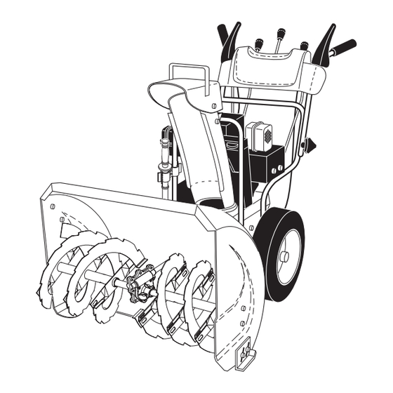
OPERATION KNOW YOUR SNOW THROWER READ THIS OWNER'S MANUAL AND ALL SAFETY RULES BEFORE OPERATING YOUR SNOW THROWER. Compare the illustrations with your snow thrower to familiarize yourself with the location of various controls and adjustments. Save this manual for future reference. These symbols may appear on your snow thrower or in literature supplied with the product. - Page 8 OPERATION SPARK ENGINE OIL CAP AUGER DRIVE DISCHARGE TRACTION PLUG, DIPSTICK CONTROL SPEED CHUTE DRIVE SAFETY CONTROL CONTROL CONTROL IGNITION LEVER LEVER GASOLINE FILLER CHUTE CHOKE DEFLECTOR CON- PLUG THROTTLE / ENGINE CONTROL DISC CHUTE RECOIL STARTER HANDLE PRIMER FUEL HANDLE KNOB SHUT-OFF...
- Page 9 OPERATION The operation of any snow thrower can result TO USE CHOKE CONTROL (See Fig. 11) in foreign objects thrown into the eyes, which The choke control is located on the engine, Use the choke can result in seve re eye damage Always wear control whenever you are starting a cold engine, Do not safety glasses or eye shields while operating use to start a warm engine,...
- Page 10 OPERATION HIGH POSITION DISCHARGE CHUTE //_!l ×_-.I Z/Y//\\ TOOL KNOB CHUTE DEFLECTOR LOW POSITION FIG. 15 TO MOVE FORWARD AND BACKWARD (See Fig. 16) FIG. 13 SELF-PROPELLING, forward and reverse movement of TO THROW SNOW (See Fig. 14) the snow thrower, is controlled by the traction drive control The auger rotation is controlled by the auger control lever lever located on the left side handle.
- Page 11 OPERATION TO ADJUST SKID PLATES (See Fig. 17) NOTE: The wrench provided in your parts bag may be used fuel. Do not store, spill or use gasoline WARNING: Wipe off any spilled oil or to adjust the skid plates. near an open flame. Skid plates are located on each side of the auger housing and adjust the clearance between the scraper bar and the CAUTION:...
- Page 12 OPERATION SNOW THROWING TIPS Pull recoil starter handle quickly. Do not allow starter rope to snap back, • Always operate the snow thrower with the engine at When the engine starts, release the recoil starter full throttle. Full throttle offers the best performance. handle and slowly move the choke control to the OFF •...
-
Page 13: Maintenance
MAINTENANCE MAINTENANCE FILL IN DATES AS YOU COMPLETE REGULAR SERVICE Check for Loose Fasteners Clean/Inspect Snow Thrower Check/Replace V-Belts RE Lubrication Chart Check Engine Oil Level Change Engine Oil Inspect Muffler Check / Replace Spark Plug Empty Fuel Tank GENERAL RECOMMENDATIONS LUBRICATION CHART... - Page 14 MAINTENANCE AUGER GEAR CASE • Oil will drain more freely when warm. • Catch oil in a suitable container, • The gear case was filled with lubricant to the proper level at the factory. The only time the lubricant needs NOTE: The left side wheel may be removed from snow attention is if service has been performed on the gear thrower for easier access to the oil drain plug and place-...
-
Page 15: Service And Adjustments
SERVICE AND ADJUSTMENTS WARNING: To avoid serious injury, before performing any service or adjustments: Remove safety ignition key. Be sure throttle is in STOP position• • Make sure the augers and all moving parts have completely stopped• Disconnect spark plug wire from spark plug and place wire where it cannot contact plug. CAUTION: Do not substitute•... - Page 16 SERVICE AND ADJUSTMENTS 12. Install the two (2) hex bolts and lock washers and WARNING: Belt replacement requires tighten securely. separation of the snow thrower. While separating the auger housing from the 13, INSTALL ENGINE PULLEY- Place beltin pulley groove &...
-
Page 17: Storage
SERVICE AND ADJUSTMENTS ENGINE SPEED NOTE: To seal punctures or prevent flat tires due to slow leaks, tire sealant may be purchased from your local parts Never tamper with the engine governor, which is factory set dealer.Tire sealant also prevents tire dry rot and corrosion, for proper engine speed, Overspeeding the engine above the factory high speed setting can be dangerous and will ENGINE... -
Page 18: Troubleshooting
TROUBLESHOOTING See appropriate section in manual unless directed to a qualified service centre. PROBLEM CAUSE CORRECTION Does not start Fuel shut-off valve (if so 1, Turn fuel shut-off valve to OPEN position. equipped) in OFF position, Safety ignition key Insert safety ignition key. is not inserted. - Page 19 SERVICE NOTES...
- Page 20 REPAIR PARTS SNOW THROWER - - MODEL NO. PR524 (96192000100) AUGER HOUSING / IMPELLER ASSEMBLY 6__/1,_,_-j\v _ 39 20 23 24...
- Page 21 REPAIR PARTS SNOW THROWER - - MODEL NO. PR524 (96192000100) AUGER HOUSING / IMPELLER ASSEMBLY PART DESCRIPTION 191079 Pulley, Impeller 188909 Bearing Assembly, Flange 155377 Nut, Hex Flange 5/16-18 180355 Bolt, Flat Head, Carriage 5/16-18 x 5/8 72270505 Bolt, Carriage 5/16-18 x 5/8...
- Page 22 REPAIR PARTS SNOW THROWER - - MODEL NO. PR524 (96192000100) CONTROL PANEL / DISCHARGE CHUTE...
- Page 23 REPAIR PARTS SNOW THROWER - - MODEL NO. PR524 (96192000100) CONTROL PANEL / DISCHARGE CHUTE PART DESCRIPTION 183334 Knob, Lever 17501010 Screw #10-24 x 5/8 179096X479 Strap, Slotted 73800600 Nut, Lock 3/8-16 19131316 Washer, Flat 3/8 178659 Control Assembly, Chute Rotater...
- Page 24 REPAIR PARTS SNOW THROWER - - MODEL NO. PR524 (96192000100) HANDLES 28 3. \\\\ _ ..32...
- Page 25 REPAIR PARTS SNOW THROWER - - MODEL NO. PR524 (96192000100) HANDLES PART DESCRIPTION 178875X479 Lever, Auger Control, RH 178648X479 Lever, Traction Drive Control, LH 179439 Nut, Cage 1/4-20 178888 Bushing, Flange 169675 Retainer, Hairpin 180402 Screw, Hex Head 1/4-20 x 3/4...
- Page 26 REPAIR PARTS SNOW THROWER - - MODEL NO. PR524 (96192000100) DRIVE...
- Page 27 REPAIR PARTS SNOW THROWER - - MODEL NO. PR524 (96192000100) DRIVE PART DESCRIPTION 146315 Screw, Hex Head 5/16-18 x 3/4 73800500 Nut, Lock 5/16-18 155415 Washer, Flat 17490508 Screw, Hex Head 5/16-18 x 1/2 180017 Bearing, Flange 180134 Shaft, Auxiliary...
- Page 28 REPAIR PARTS SNOW THROWER-- MODEL NO. PR524 (96192000100) CHASSIS / ENGINE / PULLEYS ..----3 <_"...
-
Page 29: Repair Parts
REPAIR PARTS SNOW THROWER - - MODEL NO. PR524 (96192000100) CHASSIS / ENGINE / PULLEYS KEY PART PART DESCRIPTION DESCRIPTION 155452 181044 Spring, Traction Idler Guide, Belt 180522 192213 Pulley, Idler (2-1/4) Belt Cover Assembly Engine, Tecumseh, Model Number (Includes Toolbox Cover) - Page 30 REPAIR PARTS SNOW THROWER - - MODEL NO. PR524 (96192000100) WHEELS / DECALS...
- Page 31 REPAIR PARTS SNOW THROWER - - MODEL NO. PR524 (96192000100) WHEELS / DECALS PART DESCRIPTION 187831 Wheel Assembly, 16", LH 155443 Pin, Klik 1/4 187866 Wheel Assembly, 16", RH 146315 Screw, Hex Head 5/16-18 x 3/4 179830 Bearing, Axle 174697 Washer, Thrust (1")
-
Page 32: Warranty
LIMITED WARRANTY The Manufacturer warrants to the original consumer purchaser that this product as manufactured is free from defects in materials and workmanship, For a period of two (2) years from date of purchase by the original consumer pur- chaser, we will repair or replace, at our option, without charge for parts or labor incurred in replacing parts, any part which we find to be defective due to materials or workmanship.
Need help?
Do you have a question about the PR524 and is the answer not in the manual?
Questions and answers