Table of Contents
Advertisement
Advertisement
Table of Contents

Related Manuals for Kenwood TK-2212


Summary of Contents for Kenwood TK-2212
-
Page 1: Instruction Manual
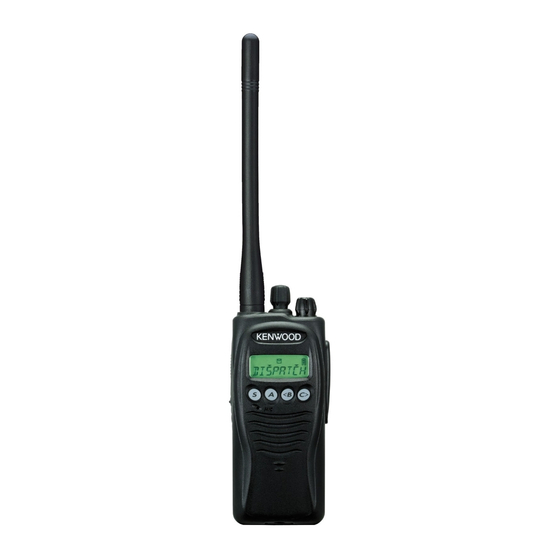
TK-2212/ TK-3212 VHF FM TRANSCEIVER/ UHF FM TRANSCEIVER INSTRUCTION MANUAL ÉMETTEUR-RÉCEPTEUR FM VHF/ ÉMETTEUR-RÉCEPTEUR FM UHF MODE D’EMPLOI TRANSCEPTOR DE FM VHF/ TRANSCEPTOR DE FM UHF MANUAL DE INSTRUCCIONES © B62-1817-00 (K, K2, M, M2) 09 08 07 06 05 04 03 02 01 00... - Page 2 VHF FM TRANSCEIVER/ UHF FM TRANSCEIVER TK-2212/ TK-3212 INSTRUCTION MANUAL...
- Page 3 HANK We are grateful you chose KENWOOD for your land mobile radio applications. We believe this easy-to-use transceiver will provide dependable communications to keep personnel operating at peak efficiency. KENWOOD transceivers incorporate the latest in advanced technology. As a result, we feel strongly that you will be pleased with the quality and features of this product.
- Page 4 For information on Ni-MH battery recycling in your area, call (toll free) 1-800-8-BATTERY (1-800-822-8837). KENWOOD’s involvement in this program is part of our commitment to preserve our environment and conserve our natural resources.
- Page 5 Ensure that there are no metallic items located between the transceiver and the battery pack. • Do not use options not specified by KENWOOD. • If the die-cast chassis or other transceiver part is damaged, do not touch the damaged parts.
- Page 6 If an abnormal odor or smoke is detected coming from the transceiver, switch the transceiver power off immediately, remove the battery pack from the transceiver, and contact your KENWOOD dealer. • Use of the transceiver while you are driving may be against traffic laws.
-
Page 7: Table Of Contents
CONTENTS UNPACKING AND CHECKING EQUIPMENT ......1 ..........1 UPPLIED CCESSORIES PREPARATION ............3 ........... 3 HARGING THE ATTERY ....... 5 NSTALLING EMOVING THE ATTERY ..........6 NSTALLING THE NTENNA ..........6 NSTALLING THE ..... 7 NSTALLING THE AP OVER THE PEAKER ICROPHONE ACKS... - Page 8 DTMF SIGNALING ............ 22 ............22 QUELCH ............24 ELECTIVE ............... 26 DTMF N ..........26 UMBER ISPLAY QUIET TALK (QT)/ DIGITAL QUIET TALK (DQT) ....27 (OST) ........27 PERATOR ELECTABLE VOICE OPERATED TRANSMISSION (VOX) ......28 VOX G ............
-
Page 9: Unpacking And Checking Equipment
UNPACKING AND CHECKING EQUIPMENT Note: The following unpacking instructions are for use by your KENWOOD dealer, an authorized KENWOOD service facility, or the factory. Carefully unpack the transceiver. We recommend that you identify the items listed in the following table before discarding the packing material. - Page 10 VHF Antenna UHF Antenna UHF Antenna (K, M types only) (K, M types only) (K2, M2 types only) Ni-MH battery pack Battery charger AC adaptor AC adaptor (K, K2 types only) (M, M2 types only) Belt clip Speaker/ Speaker/ Screw set microphone microphone jacks cap...
-
Page 11: Preparation
PREPARATION HARGING THE ATTERY The battery pack is not charged at the factory; charge it before use. Initially charging the battery pack after purchase or extended storage (greater than 2 months) will not bring the battery pack to its normal operating capacity. After repeating the charge/ discharge cycle two or three times, the operating capacity will increase to normal. - Page 12 1 Plug the AC adaptor cable into the adaptor jack located on the rear of the charger. 2 Plug the AC adaptor into an AC outlet. 3 Slide the battery pack or a transceiver with a battery pack into the charger. •...
-
Page 13: Installing / Removing The Battery Pack
NSTALLING EMOVING THE ATTERY ◆ Do not short the battery terminals or dispose of the battery by fire. ◆ Never attempt to remove the casing from the battery pack. 1 Align the battery pack with the back of the transceiver, then press the battery pack and transceiver firmly together until the release latch on the base... -
Page 14: Installing The Antenna
NSTALLING THE NTENNA Screw the antenna into the connector on the top of the transceiver by holding the antenna at its base and turning it clockwise until secure. Note: The antenna is neither a handle, a key ring retainer, nor a speaker/ microphone attachment point. -
Page 15: Installing The Cap Over The Speaker / Microphone Jacks
NSTALLING THE AP OVER THE PEAKER ICROPHONE ACKS If you are not using an optional speaker/ microphone, install the cap over the speaker/ microphone jacks using the supplied 3 x 6 mm screw. Note: To keep the transceiver water resistant, you must cover the speaker/ microphone jacks with the supplied cap. -
Page 16: Getting Acquainted
GETTING ACQUAINTED Microphone Speaker... - Page 17 q q q q q Antenna connector Connect an antenna here {page 6}. w w w w w Selector Your dealer can program the selector as either Zone Up/ Down (default setting) or Channel Up/Down. Rotate the selector to select a zone or channel. e e e e e Power switch/ Volume control Turn clockwise to switch ON the transceiver.
-
Page 18: Display
!1 !1 !1 !1 !1 S key Press to activate its programmable function {page 12}. The default setting is None (no function). !2 !2 !2 !2 !2 A key Press to activate its programmable function {page 12}. The default setting is None (no function). !3 !3 !3 !3 !3 <B key Press to activate its programmable function {page 12}. - Page 19 e l i n i l y t i e l i v i t / l l c i f y l t...
-
Page 20: Programmable Functions
PROGRAMMABLE FUNCTIONS Side 1, Side 2, S, A, <B, and C> keys {pages 9 and 10} can be programmed with the functions listed below. Please contact your dealer for further details on these functions. Note: The selector can be programmed as either Zone Up/Down or Channel Up/Down. -
Page 21: Basic Operations
BASIC OPERATIONS ON/OFF WITCHING OWER Turn the Power switch/ Volume control clockwise to switch the transceiver ON. • A beep sounds and the display momentarily lights up. • If the Transceiver Password function is programmed, “PASSWORD” appears on the display. Enter the password to unlock the transceiver (refer to “Transceiver Password”, below). -
Page 22: Selecting A Zone And Channel
ELECTING A ONE AND HANNEL Select the desired zone using the selector or the keys programmed as Zone Up/ Zone Down. • The default setting for the selector is Zone Up/ Down. Select the desired channel using the selector or the keys programmed as Channel Up/ Channel Down. -
Page 23: Scan
SCAN If the Scan function is programmed, zones or channels can be scanned by pressing the key programmed as Scan. Scan can be used as either Single Scan or Multi Scan. • Single Scan monitors only the channels of the currently selected zone, which have been added to the scanning sequence. -
Page 24: Add To Scan / Delete From Scan
DD TO ELETE FROM Press the key programmed as Scan Delete/Add to add or remove each channel to or from the scan sequence. • The channel add indicator ( ) will appear on the display when the selected channel is added to the scan sequence. -
Page 25: Revert Channel
EVERT HANNEL During Scan, pressing the PTT switch to transmit will cause the transceiver to select the revert channel. Your dealer can program one of the following six types of Revert channels for your transceiver: • Selected: The zone/ channel selected prior to activating Scan is assigned as the new revert zone and channel. -
Page 26: Fleetsync: Alphanumeric 2-Way Paging Function
FleetSync: ALPHANUMERIC 2-WAY PAGING FUNCTION FleetSync is an Alphanumeric 2-way Paging Function, and is a protocol owned by KENWOOD Corporation. FleetSync enables a variety of paging functions on your transceiver, some of which depend on dealer programming. ELCALL ELECTIVE ALLING A Selcall is a voice call to a particular station or to a group of stations. -
Page 27: Status Message
■ Identification Codes An ID code is a combination of a 3-digit Fleet number and a 4-digit ID number. Each transceiver must have its own Fleet and ID number. • Enter a Fleet number (100 ~ 349) to make a group call. •... - Page 28 ■ Transmitting 1 Select your desired zone and channel. 2 Press the key programmed as Status to enter Status mode or Selcall + Status to enter Selcall mode. • When using the Status key to enter Status mode, the target Fleet/ ID is fixed and cannot be selected. Skip to step 5 to continue.
-
Page 29: Reviewing Messages In The Stack Memory
■ Reviewing Messages in the Stack Memory 1 Press and hold the key programmed as Selcall, Status, or Selcall + Status for 1 second to enter the Stack memory. • The last received message is displayed with the message number. 2 Press the <B and C>... -
Page 30: Dtmf Signaling
DTMF SIGNALING QUELCH Code Squelch is enabled or disabled by your dealer. This function turns the transceiver squelch OFF only when it receives the DTMF code that has been set up in your transceiver. Transceivers that do not transmit the correct code will not be heard. - Page 31 ■ Autodial 1 Press the key programmed as Autodial. • The first entry in the Autodial list appears on the display. 2 Press the <B and C> keys to select your desired Autodial list number. 3 Press the PTT switch or Side 2 key to make the call. ■...
-
Page 32: Selective Call
ELECTIVE Selective Call is enabled or disabled by your dealer. This function is similar to Code Squelch {page 20}. The differences from Code Squelch are as follows: • You can transmit or receive message codes containing a maximum of 5 digits. •... - Page 33 ■ Autodial 1 Press the key programmed as Autodial. • The first entry in the Autodial list appears on the display. 2 Press the <B and C> keys to select your desired Autodial list number. 3 Press the PTT switch or Side 2 key to make the call. ■...
-
Page 34: Stun
This function is used when a transceiver is stolen or lost. When the transceiver receives a call containing a stun code, either transmit mode will be disabled, or both receive mode and transmit mode will be disabled. The stun code is cancelled when the transceiver receives a call with a revive code. -
Page 35: Quiet Talk (Qt)/ Digital Quiet Talk (Dqt)
QUIET TALK (QT)/ DIGITAL QUIET TALK (DQT) Your dealer may have programmed QT or DQT signaling on your transceiver channels. A QT tone/ DQT code is a sub-audible tone/code which allows you to ignore (not hear) calls from other parties who are using the same channel. When a channel is set up with a QT tone or DQT code, squelch will only open when a call containing a matching tone or code is received. -
Page 36: Voice Operated Transmission (Vox)
VOICE OPERATED TRANSMISSION (VOX) VOX can be activated or deactivated by your dealer. VOX operation allows you to transmit hands-free. This feature can only be used if you are using a supported headset. When operating VOX, you must set a VOX Gain level. This setting allows the transceiver to recognize sound levels. -
Page 37: Vox Operation
VOX O PERATION 1 Connect the headset to the transceiver. • The VOX function does not activate when a headset is not connected to the accessory terminal of the transceiver. 2 Press and hold the key programmed as VOX for 2 seconds. -
Page 38: Advanced Operations
ADVANCED OPERATIONS ELECTING A RANSMIT OWER Each channel is programmed with either high or low transmit power by your dealer. You can change the transmit power of only channels programmed as high. When you can reliably communicate with other parties without using high transmit power, select low transmit power by pressing the key programmed as Low Transmission Power. -
Page 39: Monitor / Squelch Off
ONITOR QUELCH You can use the key programmed as Monitor/ Squelch Off to listen to weak signals that you cannot hear during normal operation and to adjust the volume when no signals are present on your selected channel. • icon appears on the display while Monitor/ Squelch Off is active. -
Page 40: Scrambler
CRAMBLER Although the scrambler function does not offer complete privacy with your calls, it does prevent others from easily listening in on your calls. When activated, the transceiver distorts your voice so that anybody listening to your call will be unable to clearly hear what you are saying. In order for members of your own group to clearly hear your call while you are using the scrambler, all other members must also activate the scrambler functions on their... -
Page 41: Transceiver Backlight
RANSCEIVER ACKLIGHT To turn the transceiver display and keypad backlight on, press the key programmed as Lamp. • Pressing any key other than the PTT switch and the Power switch/ Volume control while the backlight is on will reset the backlight timer, allowing it to remain lit for an additional 5 seconds. -
Page 42: Background Operations
BACKGROUND OPERATIONS (TOT) IMER The purpose of the Time-out Timer is to prevent any caller from using a channel for an extended period of time. Your dealer can program the TOT in the range of 15 seconds to 10 minutes. If you continuously transmit for a period of time that exceeds this programmed time, the transceiver will stop transmitting and an alert tone will sound. -
Page 43: Battery Power Indicator
ATTERY OWER NDICATOR The battery power indicator displays the battery power remaining, as illustrated below: High Sufficient Very low (flashing) When the battery power is very low, replace or recharge the battery pack. If activated by your dealer, an alert tone will sound every 30 seconds and the LED indicator will blink red when the battery power is low while transmitting.
Need help?
Do you have a question about the TK-2212 and is the answer not in the manual?
Questions and answers