Table of Contents
Advertisement
Your new tool has been engineered and manufactured to Ryobi's high standard for dependability, ease of operation, and
operator safety. When properly cared for, it will give you years of rugged, trouble-free performance.
WARNING:
To reduce the risk of injury, the user must read and understand the operator's manual before using
this product.
Thank you for buying a Ryobi Product.
SAVE THIS MANUAL FOR FUTURE REFERENCE
OPERATOR'S MANUAL
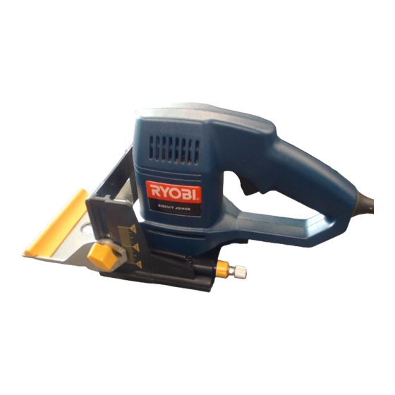
PLATE JOINER
JM81-1
DOUBLE INSULATED
Advertisement
Table of Contents

Related Manuals for Ryobi JM81-1


Summary of Contents for Ryobi JM81-1
- Page 1 PLATE JOINER JM81-1 DOUBLE INSULATED Your new tool has been engineered and manufactured to Ryobi's high standard for dependability, ease of operation, and operator safety. When properly cared for, it will give you years of rugged, trouble-free performance. WARNING: To reduce the risk of injury, the user must read and understand the operator's manual before using this product.
-
Page 2: Table Of Contents
TABLE OF CONTENTS Introduction ..................................2 General Safety Rules ..............................3-4 Specific Safety Rules ..............................4 Symbols ................................... 5 Electrical ..................................6 Features ..................................7-8 Adjustments ................................9-10 Operation ................................. 11-16 Maintenance ................................17-19 Accessories ................................... 19 Troubleshooting ................................20 Service Information ............................... -
Page 3: General Safety Rules
GENERAL SAFETY RULES switch or plugging in tools that have the switch on invites WARNING: accidents. Remove adjusting keys or wrenches before turning Read and understand all instructions. Failure to fol- the tool on. A wrench or a key that is left attached to a low all instructions listed below, may result in electric rotating part of the tool may result in personal injury. -
Page 4: Specific Safety Rules
GENERAL SAFETY RULES SERVICE When servicing a tool, use only identical replacement parts. Follow instructions in the Maintenance section Tool service must be performed only by qualified re- of this manual. Use of unauthorized parts or failure to pair personnel. Service or maintenance performed by follow Maintenance Instructions may create a risk of shock unqualified personnel may result in a risk of injury. -
Page 5: Symbols
SYMBOLS Important: Some of the following symbols may be used on this tool. Please study them and learn their meaning. Proper interpretation of these symbols will allow you to operate the tool better and safer. SYMBOL NAME DESIGNATION/EXPLANATION Volts Voltage Amperes Current Hertz... -
Page 6: Electrical
DOUBLE INSULATION When using a power tool at a considerable distance from a Your Ryobi power tool is double insulated. This means you power source, be sure to use an extension cord that has the are separated from the tool's electrical system by two complete capacity to handle the current the tool will draw. -
Page 7: Features
FEATURES SPECIFICATIONS No Load Speed ..............................10,000 rpm Rating ..........................120 volts, 60 HZ, AC, 6.0 Amperes ° Fence Angle Adjustment With 45 Positive Stops ..................... 0 - 135° Depth Of Cut With Micro Depth Of Cut Adjustment .................. 0 - 5/8 in. (16mm) Net Weight .............................. - Page 8 If any parts are damaged or missing, contact your local Ryobi factory or authorized service center to obtain replacement parts before attempting to operate your plate joiner.
-
Page 9: Adjustments
ADJUSTMENTS WARNING: If any parts are missing, do not operate tool until the missing parts are replaced. Failure to do so could result ROTATE TO DESIRED SETTING in possible serious personal injury. 0, 10, OR 20 PULL AND HOLD DEPTH OF CUT ADJUSTMENTS TO ROTATE DEPTH Your plate joiner can be adjusted to three standard cutting ADJUSMENT... -
Page 10: Adjustments
ADJUSTMENTS FENCE HEIGHT ADJUSTMENT See Figure 5. The adjustable fence on your plate joiner can be moved up FRONT HANDLE / and down to adjust the position of the blade in relation to the ADJUSTMENT top of the workpiece. A scale on both sides of the fence FENCE indicates the height of the fence from the center of the blade. -
Page 11: Operation
OPERATION Plug your plate joiner into power supply and prepare to WARNING: make your first cut. Grasp and hold your plate joiner securely with both hands by the front and rear handles Always wear safety goggles or safety glasses with side as shown on page 3. - Page 12 OPERATION Finally, disassemble the workpieces and place a bead of Once all biscuit slots have been cut, place a biscuit in glue in each slot. Also, spread a bead of glue over the each joint and dry assemble the workpieces. Make sure entire surface of the joint.
- Page 13 OPERATION OFFSET BUTT JOINTS CENTERLINE See Figure 10. MARK (S) The rails of a table or workbench are often offset from the front of the table legs. When offsets are required, it is necessary to cut the slots in the rails first, then re-adjust the BISCUIT (S) fence to cut the slots in the legs.
- Page 14 OPERATION Place your plate joiner on vertical board as shown in figure 15 and align indicator marks on base assembly with centerline on vertical board. Place a straight piece of wood on the vertical board and securely clamp it flush against the base assembly. This piece of wood is used for a fence or guide.
- Page 15 OPERATION Align indicator mark on fence with the centerline on the workpiece. Plug your plate joiner into power supply and prepare to cut slot. Depress the switch trigger to turn the power on your plate BISCUIT joiner, then push it forward to extend the blade into the SLOT wood.
-
Page 16: Operation
OPERATION Once all slots have been cut, place a biscuit in each joint and dry assemble the workpieces. Make sure each joint lines up and fits. ADAPTER RETAINER Finally, disassemble workpieces and place a bead of STRIP glue in each slot. Also, spread a bead of glue over the entire surface of the joint. -
Page 17: Maintenance
MAINTENANCE WARNING: ADJUSTABLE FENCE REMOVE When servicing, use only identical Ryobi replacement parts. Use of any other part may create a hazard or FRONT BASE ASSEMBLY cause product damage. CLEANING BASE ASSEMBLY / DUST BAG TUNNEL See Figures 21-23. After extended use, wood particles and resin may build up... - Page 18 MAINTENANCE BLADE REPLACEMENT See Figures 24-27. After extended use, the blade on your plate joiner may ADJUSTABLE FENCE REMOVE become dull and need replacing. If you accidentally hit a nail or other blunt object, it will break the carbide tips on the FRONT BASE ASSEMBLY blade.
-
Page 19: Accessories
MAINTENANCE HOW TO REPLACE THE BLADE (Continued) TO REMOVE TO TIGHTEN NOTE: Blade teeth point toward the right of the tool when held in normal operating position. The direction of rotation BLADE is marked on the joiner blade. An arrow on the bottom SCREW of the front base assembly also indicates direction of OUTER BLADE... -
Page 20: Troubleshooting
TROUBLESHOOTING PROBLEM SOLUTION 1. Biscuits do not fit slots. Biscuits not fitting slots may A. Biscuit slots are too deep or too shallow. Make fine also cause misalignment of boards being joined. adjustments to depth setting. See "TO MAKE FINE ADJUSTMENTS"... - Page 21 NOTES Page 21...
-
Page 22: Service Information
Now that you have purchased your tool, should a need ever exist for repair parts or service, simply contact your nearest Ryobi Authorized Service Center. Be sure to provide all pertinent facts when you call or visit. Please call 1-800-525-2579 for your nearest Ryobi Authorized Service Center.
Need help?
Do you have a question about the JM81-1 and is the answer not in the manual?
Questions and answers