Table of Contents
Advertisement
Available languages
Available languages
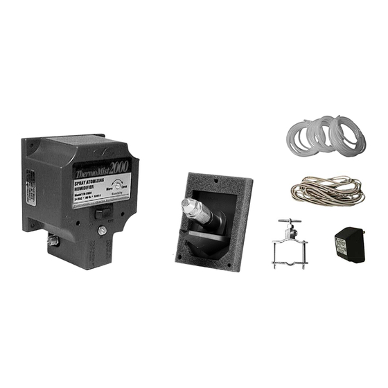
The TM-2000 Humidifier is activated by heated air being produced by your furnace. Its thermal sensing circuitry
monitors the temperature of the heated air. When the air is warm enough, the Housing Assembly's electric
water valve is actuated, opening to allow cold water from your plumbing system to be atomized into a fine mist.
This mist is discharged into the heated air by the Remote Nozzle Bracket Assembly, where it immediately
evaporates and is distributed throughout your household. The TM-2000 is supplied water from your plumbing
system by the Saddle Valve Assembly, and is safely powered with reduced voltage by the 120/24 VAC
Transformer, which plugs into an ordinary 120-volt wall outlet.
The TM-2000 is ideal for use with conventional gas or oil forced-air central heating systems.
WARNING: The TM-2000 is not be used on 90+ condensing furnaces, electric heat pumps or homes
with well-water systems.
I
: (DO NOT INSTALL HUMIDIFIER IF ALL OF THESE ITEMS ARE NOT PRESENT!)
TEMS INCLUDED IN KIT
Housing Assembly
Plastic Tubing (3 - 10' Sections)
Housing Mounting Template
Remote Mounting Template
Power Supply Wire
Quick Connect Terminals (2)
120/24 VAC Transformer
Instruction Manual
O
PTIONAL ACCESSORIES
Air Booster Activator Kit
Humidistat
NOTE:
The TM-2000 is designed to operate on normal city water supply
pressure. If any other type of water supply is to be used it must be capable of
providing a minimum pressure of 50 psi.
READ AND SAVE THESE INSTRUCTIONS FOR FUTURE REFERENCE OF REPLACEMENT PARTS, OPTIONAL
WHOLE HOUSE HUMIDIFIER
Model: TM-2000
Housing Assembly
Remote
Nozzle Bracket
:
DO NOT DESTROY
COMPONENTS, AND TROUBLESHOOTING INFORMATION.
Saddle Valve Assembly
Remote Nozzle Bracket
Saddle Valve Assembly
Includes 5 Each: Compression Nuts, sleeves, and inserts
Mounting Components
Includes: (4) #8-15 X 3/4" Hex Head Housing
(3) #8-15 X 1/2" Hex Head Remote
Bracket Mounting Screws
(3) #8 Speed Nuts For Remote Bracket Mounting.
Plastic Tubing (3-10' Sections)
10' Power Supply Wire
120VAC/24VAC
Transformer
English ...... Page 1
Français..... Page 8
Espanõl ..... Page 14
PRODUCT QUESTIONS...
CALL FIELD FIRST
for answers on product maintenance,
operation or replacement part questions.
Phone:
(252)522-3031
E-mail:
fieldtec@fieldcontrols.com
Advertisement
Table of Contents

Related Manuals for Field Controls TM-2000

Summary of Contents for Field Controls TM-2000
- Page 1 WHOLE HOUSE HUMIDIFIER The TM-2000 Humidifier is activated by heated air being produced by your furnace. Its thermal sensing circuitry monitors the temperature of the heated air. When the air is warm enough, the Housing Assembly’s electric water valve is actuated, opening to allow cold water from your plumbing system to be atomized into a fine mist.
- Page 2 PLEASE READ COMPLETELY BEFORE BEGINNING INSTALLATION! CAUTION: The TM-2000 is not to be used on electric furnaces, heat pumps, or in locations where the air temperature could drop below 40°F. The mounting position of the mounting position of the TM-2000 is very important.
- Page 3 Figure 3 Figure 5 Figure 7 Page 3 Figure 4 Figure 6 Figure 8...
- Page 4 22. Make certain the Housing Assembly’s power switch is “OFF,” and plug the transformer into the outlet. The transformer should now be supplying 24 volts AC to the TM-2000. Page 4 Figure 9...
- Page 5 Housing Assembly. 4. Lower the thermostat to end the furnace heating cycle. Check to be sure the TM-2000 deactivates at least 30 seconds before the furnace stops blowing air through the ductwork. If the TM-2000 does not deactivate soon enough, turn the adjustment knob slightly clockwise.
- Page 6 Humidistat and an Air Booster Activator. The Humidistat will allow power supply to the TM-2000 only when there is a call for humidity. The TM-2000 will still be activated only by the warm air flow. The Air Booster Activator recognizes when the blower is on and supplies power to the TM-2000 only during this time.
- Page 7 Nozzle drips continuously during operation, the water inlet filter or nozzle is becoming clogged. Replace both as necessary. c. If the nozzle drips continuously after shut down of the TM-2000, it is likely due to a faulty internal valve. Contact Field Controls for replacement.
- Page 8 4. Couper, percer ou poinçonner les trous dans le plénum, tel qu’indiqué sur le gabarit, puis retirer le gabarit. 5. Fixer soigneusement le boîtier du TM-2000 au plénum en utilisant les quatre longues vis autotaraudeuses à tête hexagonale n° 8 de 15 x ¾ po. Prendre bien soin de ne pas endommager l’élément du capteur thermique.
- Page 9 Schéma 3 Schéma 4 Schéma 5 Schéma 6 Schéma 7 Schéma 8 Page 9...
- Page 10 22. Fixer fermement le fil rouge à une des deux bornes à vis sur le transformateur 120/24 volts c.a. et le fil blanc à l’autre borne du transformateur. 23. S’assurer que l’interrupteur de l’humidificateur est en position «OFF» et brancher le transformateur dans une prise de courant. Le transformateur devrait maintenant fournir une alimentation de 24 volts c.a. au TM-2000. service Page 10 Schéma 9...
- Page 11 4. Baisser le thermostat de la fournaise pour mettre fin au cycle de chauffage. Vérifier que le TM-2000 s’éteint au moins 30 secondes avant que la fournaise ne cesse de souffler de l’air chaud dans le conduit. Si le TM-2000 ne s’éteint pas dans les délais prescrits, tourner légèrement le cadran de réglage dans le sens horaire.
- Page 12 L’activateur d’air détecte que le ventilateur est allumé et alimente alors le TM-2000 en courant. Lorsque le ventilateur est éteint et qu’il n’y a pas de circulation d’air, le TM-2000 ne peut fonctionner.
- Page 13 4. L’alimentation en eau la plus près est située à plus de 10 pieds du TM-2000. a. Si l’alimentation en eau la plus près est située à plus de 10 pieds du TM-2000, il est recommandé que la connexion soit faite uniquement avec un conduit en cuivre de même diamètre extérieur (1/4 po). Ce type de conduit est disponible dans la plupart des quincailleries.
- Page 14 La Figura 6) En ciertas instalaciones, tal vez sea necesario extender más la boquilla con un juego de opcional extensión EK-1 de Field Controls. (Vea La Figura 7) Un 45° para redirigir el rocío sin extender la boquilla. Si existe un aire acondicionado “A-COIL”...
- Page 15 Figura 3 Figura 5 Figura 7 Page 15 Figura 4 Figura 6 Figura 8...
- Page 16 El transformador debe suministrar ahora 24 voltios CA al TM-2000. JUSTE DEL UMIDIFICADOR El TM-2000 debe estar ajustado ahora de tal manera que se active después que comience la circulación de aire caliente, Page 16 Figure 9...
- Page 17 3. Aproximadamente 2 minutos después de que la caldera comience a soplar aire caliente a través de los conductos, gire la perilla de ajuste en sentido contrario de las agujas del reloj hasta que se active el TM-2000. Esto se indicará al iluminarse la luz “ON”...
- Page 18 “ON” (ENCENDIDO) para obtener mayor temperatura, o trate de localizar una posición que sea adecuada para el requerimiento de temperatura. 3. El TM-2000 se enciende después que el ventilador de la caldera se apaga o el TM-2000 se mantiene encendido después de apagarse el ventilador.
- Page 19 5. El suministro de agua más cercano está a más de 10 pies de la ubicación del TM-2000. a. Si el suministro de agua más cercano está a más de 10 pies de la ubicación del TM-2000, se recomienda que la conexión de agua se haga solamente con tubería de cobre del mismo tamaño (1/4 de pulgada de diámetro...
- Page 20 GARANTÍA LIMITADA DE UN AÑO Se garantiza que los productos de The Field Controls Co. están libres de defectos en material y mano de obra bajo uso normal durante un año a partir de la fecha de compra. En caso de un mal funcionamiento o falla de este producto, el comprador deberá empaquetar toda la unidad debidamente y enviarla con PORTE PAGADO con la dirección de regreso, a la dirección indicada a continuación.
Need help?
Do you have a question about the TM-2000 and is the answer not in the manual?
Questions and answers