Hoshizaki KML-451MAH Instruction Manual
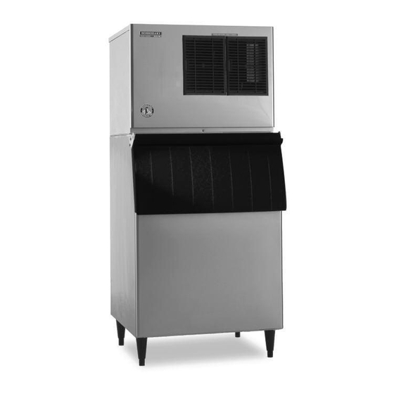
Low-profile modular crescent cuber
Hide thumbs
Also See for KML-451MAH:
- Service manual (48 pages) ,
- Parts list (26 pages) ,
- Specifications (2 pages)

Subscribe to Our Youtube Channel
Related Manuals for Hoshizaki KML-451MAH


Summary of Contents for Hoshizaki KML-451MAH
- Page 1 Hoshizaki Hoshizaki America, Inc. Low-Profile Modular Crescent Cuber Models KML-451MAH KML-451MWH INSTRUCTION MANUAL “A Superior Degree of Reliability” www.hoshizaki.com ™ Issued: 2-7-2006 Revised: 8-5-2009...
- Page 2 Should the reader have any questions or concerns which have not been satisfactorily addressed, please call, write, or send an e-mail message to the Hoshizaki Technical Support Department for assistance. HOSHIZAKI AMERICA, INC.
-
Page 3: Table Of Contents
CONTENTS Important Safety Information ....................4 I. Specifications ........................5 A. Nameplate Rating ......................5 1. KML-451MAH (air-cooled) ..................5 2. KML-451MWH (water-cooled) .................. 6 B. Dimensions/Connections ....................7 1. KML-451MAH (air-cooled) ..................7 2. KML-451MWH (water-cooled) .................. 8 II. -
Page 4: Important Safety Information
Important Safety Information Throughout this manual, notices appear to bring your attention to situations which could result in death, serious injury, or damage to the unit. WARNING Indicates a hazardous situation which could result in death or serious injury. CAUTION Indicates a situation which could result in damage to the unit. -
Page 5: Specifications
I. Specifications A. Nameplate Rating 1. KML-451MAH (air-cooled) HOSHIZAKI ICE MAKER MODEL NUMBER KML-451MAH SERIAL NUMBER AC SUPPLY VOLTAGE 115-120/60/1 COMPRESSOR 115-120V 7.9RLA 54.5LRA PUMP 120V 0.5FLA 120V 0.85FLA OTHER 115-120V 0.15A MAXIMUM FUSE SIZE 20 AMPS MAX. HACR BREAKER(USA ONLY) 20 AMPS MAX. -
Page 6: Kml-451Mwh (Water-Cooled)
2. KML-451MWH (water-cooled) HOSHIZAKI ICE MAKER MODEL NUMBER KML-451MWH SERIAL NUMBER AC SUPPLY VOLTAGE 115-120/60/1 COMPRESSOR 115-120V 9.0RLA 70LRA PUMP 120V 0.5FLA OTHER 115-120V 0.15A MAXIMUM FUSE SIZE 20 AMPS MAX. HACR BREAKER(USA ONLY) 20 AMPS MAX. CIRC. BREAKER (CANADA ONLY) -
Page 7: Dimensions/Connections
B. Dimensions/Connections 1. KML-451MAH (air-cooled) -
Page 8: Kml-451Mwh (Water-Cooled)
2. KML-451MWH (water-cooled) -
Page 9: Installation And Operating Instructions
• This icemaker can be installed on a dispenser unit or storage bin 30" wide or wider. The following are recommended: Hoshizaki Dispenser, Model DB-200 or DM series; Hoshizaki Ice Storage Bin, Model B-500 series. For further options, contact your local Hoshizaki distributor. B. How to Remove Panels See Fig. -
Page 10: Location
C. Location CAUTION 1. This icemaker is not intended for outdoor use. Normal operating ambient temperature should be within 45°F to 100°F (7°C to 38°C); Normal operating water temperature should be within 45°F to 90°F (7°C to 32°C). Operation of the icemaker, for extended periods, outside of these normal temperature ranges may affect icemaker performance. -
Page 11: Electrical Connection
E. Electrical Connection WARNING 1. Electrical connection must be hard-wired and must meet national, state, and local electrical code requirements. Failure to meet these code requirements could result in death, electric shock, serious injury, fire, or severe damage to equipment. 2. -
Page 12: Water Supply And Drain Connections
10 PSIG. Do not run the icemaker until the proper water pressure is reached. • A plumbing permit and services of a licensed plumber may be required in some areas. • External filters, strainers, or softeners may be required depending on water quality. Contact your local Hoshizaki distributor for recommendations. • Water supply pressure should be a minimum of 10 PSIG and a maximum of 113 PSIG. If the pressure exceeds 113 PSIG, the use of a pressure reducing valve is required. • The icemaker drain line, dispenser unit/storage bin drain line, and water-cooled condenser drain line (if applicable) must be run separately. -
Page 13: Icemaker
Icemaker Water Supply Line Drain Valve Bin Drain Outlet 3/4" FPT Separate piping to approved drain. Leave a 2-inch (5-cm) vertical air Icemaker gap between the end of each pipe Drain Outlet and the drain. 3/4" FPT 2-inch (5-cm) air gap Floor Drain KML-451MAH Fig. 4... -
Page 14: Water-Cooled Condenser
2. Water-Cooled Condenser a) Connection to an Open Drain System • Condenser water supply inlet is 1/2" female pipe thread (FPT). A minimum of 3/8" OD copper tubing is recommended for the condenser water supply line. • A condenser water supply line shut-off valve and drain valve should be installed. • Condenser drain outlet is 3/8" FPT. A minimum of 3/8" OD hard pipe is recommended for the condenser drain line. • In some areas, a back flow preventer may be required in the cooling water circuit. Icemaker Water Supply Line Icemaker Shut-Off Valve Water Supply Icemaker Inlet Condenser Water Supply Line 1/2" FPT Shut-Off Valve Condenser... -
Page 15: B) Connection To A Closed Loop System
b) Connection to a Closed Loop System • Condenser water supply inlet is 1/2" female pipe thread (FPT). A minimum of 3/8" OD copper tubing is recommended for the condenser water supply line. • Condenser return outlet is 3/8" FPT. A minimum of 3/8" OD hard pipe is recommended for the condenser return line. • Shut-off valves and drain valves should be installed at both the condenser water supply inlet and condenser return outlet. • The water supply to the condenser should not drop below 4 GPM. • The pressure differential between the condenser water supply inlet and condenser return outlet must be no less than 10 PSIG. • When using a glycol blend, the solution mixture should be less than 30% glycol. • In order to maintain the proper high side pressure, the condenser water supply inlet temperature should not drop below 45°F (7°C) and the condenser return outlet temperature must be in the 104°F to 115°F (40°C to 46°C) range. -
Page 16: Final Checklist
G. Final Checklist WARNING CHOKING HAZARD: Ensure all components, fasteners, and thumbscrews are securely in place after installation. Make sure that none have fallen into the dispenser unit/storage bin. 1) Is the icemaker level? 2) Is the icemaker in a site where the ambient temperature is within 45°F to 100°F (7°C to 38°C) and the water temperature within 45°F to 90°F (7°C to 32°C) all year around? 3) Is there at least 6" (15 cm) clearance at sides, rear, and top of the icemaker for proper air circulation and ease of maintenance and service? -
Page 17: Startup
H. Startup WARNING 1. All parts are factory-adjusted. Improper adjustments may adversely affect safety, performance, component life, and warranty coverage. 2. If the icemaker is turned off, wait for at least 3 minutes before restarting the icemaker to prevent damage to the compressor. 3. -
Page 18: Cleaning And Maintenance
A. Cleaning and Sanitizing Instructions Hoshizaki recommends cleaning and sanitizing this unit at least once a year. More frequent cleaning and sanitizing, however, may be required in some existing water conditions. - Page 19 8) In bad or severe water conditions, clean the float switch assembly as described below. Otherwise, continue to step 9. a. Remove the 3 screws securing the float switch assembly, then remove the assembly. b. Remove the retainer rod from the bottom of the float switch housing, then remove the float.
-
Page 20: Sanitizing Procedure - Following Cleaning Procedure
2. Sanitizing Procedure - Following Cleaning Procedure 1) Dilute 1.0 fl. oz. (30 ml or 2.0 tbs) of a 5.25% sodium hypochlorite solution (chlorine bleach) with 2.0 gal. (7.6 l) of warm water. 2) Remove the front insulation panel. 3) Pour the sanitizing solution into the water tank. 4) Move the service switch to the "WASH" position. 5) Replace the front insulation panel and the front panel in their correct positions. 6) Turn on the power supply to start the sanitizing process. -
Page 21: Maintenance
B. Maintenance This icemaker must be maintained individually, referring to the instruction manual and labels provided with the icemaker. WARNING 1. Only qualified service technicians should attempt to service or maintain this icemaker. 2. Disconnect power before performing service or maintenance. 1. -
Page 22: Preparing The Icemaker For Long Storage
C. Preparing the Icemaker for Long Storage CAUTION 1. When storing the icemaker for an extended time or in sub-freezing temperatures, follow the instructions below to prevent damage. 2. To prevent damage to the water pump, do not leave the control switch in the "SERVICE" position for extended periods of time when the water tank is empty. - Page 23 3) Open the condenser water supply line drain valve. If connected to a closed loop system, also open the condenser return line drain valve. 4) Attach a compressed air or carbon dioxide supply to the condenser water supply line drain valve. 5) Open the water regulating valve by using a screwdriver to pry up on the spring retainer underneath the spring.
- Page 24 HOSHIZAKI AMERICA, INC. 618 Hwy. 74 S., Peachtree City, GA 30269 USA TEL (770) 487-2331 FAX (770) 487-3360 www.hoshizaki.com 91A1BG10C...
Need help?
Do you have a question about the KML-451MAH and is the answer not in the manual?
Questions and answers