
Related Manuals for QSC Q-SYS TSC-8-BK

Summary of Contents for QSC Q-SYS TSC-8-BK
- Page 1 ™ Hardware User Manual TSC-8-BK – Networked 8.4" Touchscreen Controller – Black TSC-8-WH – Networked 8.4" Touchscreen Controller – White TSC-8-BX – 8.4" Touchscreen Controller Back Box TD-000340-00-B *TD-000340-00*...
-
Page 2: Important Safety Instructions
EXPLANATION OF TERMS AND SYMBOLS The term “WARNING!” indicates instructions regarding personal safety. If the instructions are not followed the result may be bodily injury or death. The term “CAUTION!” indicates instructions regarding possible damage to physical equipment. If these instructions are not followed, it may result in damage to the equipment that may not be covered under the warranty. -
Page 3: Fcc Statement
Damage to, or loss of any software or data residing on the product is not covered. When providing repair or replacement service, QSC will use reasonable efforts to reinstall the product’s original software configuration and subsequent update releases, but will not provide any recovery or... -
Page 4: Rohs Statement
RoHS STATEMENT The Q-Sys TSC-8-BK and TSC-8-WH products are in compliance with European Directive 2002/95/EC – Restriction of Hazardous Substances (RoHS). The Q-Sys TSC-8-BK and TSC-8-WH products are in compliance with “China RoHS” directives. The following chart is provided for product use in China and its territories: Q-Sys TSC-8-BK, Q-Sys TSC-8-WH 部件名称... - Page 5 The TSC-8 series products are network enabled capacitive touchscreen control panels. The TSC-8 products are designed to connect to a Q-Sys system via Q-LAN or to an auxiliary network to which the system Core Processor(s) is connected. Q-LAN is QSC’s proprietary time-sensitive gigabit Ethernet network implementation built on standard protocols and off-the-shelf network hardware and cabling.
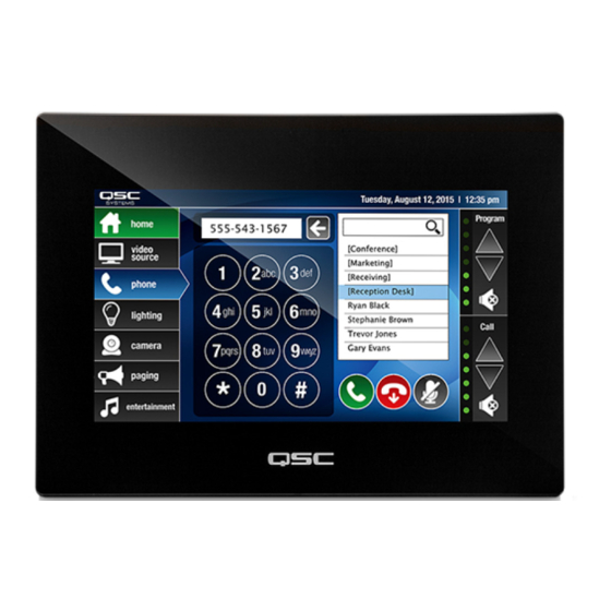
- Page 6 TSC-8 Front Panel Features — Figure 1 — 1. Capacitive-touch control surface and LCD viewing area (8.4" diagonal) 2. Bezel mounting points 3. Bezel mounting point cap...
- Page 7 TSC-8 Rear Panel and Connector Edge Features — Figure 2 — 1. Cooling fins 7. USB 2.0 host port interfaces (type A) – not used 2. Mounting point Standoff slots 8. Device Restart (on left side if you are facing the touchscreen) 3.
- Page 8 TSC-8-BX Back Box Features — Figure 3 — 1. Mounting Brackets 7. Flange 2. Mounting Bracket screws, M3x5L, large-dia., truss-head, Phillips (10) 8. Bezel Mounting Standoffs 3. AC Connection pigtail 9. Cable Access opening 4. Back Box Mounting Tabs 10. Back Box 5.
- Page 9 The Q-Sys solution (Figure 4) is designed to be deployed on QSC’s high performance Q-LAN network. Q-LAN is a proprietary network implementation that bundles several industry standard protocols into a data transport solution appropriate for live performance multimedia environments. Q-LAN offers gigabit data rates, device and network redundancy, 32-bit floating point audio data transfers, and low-latency support on local area network deployments.
-
Page 10: Installation
If service is required and the original packing material is not available, ensure that the unit is adequately protected for shipment (use a strong box of appropriate size, sufficient packing/padding material to prevent load shifting or impact damage) or call QSC’s Technical Services Group for replacement packing material and a carton. - Page 11 Mounting the TSC-8 in an Existing all or Podium This procedure covers mounting the Back Box with Flange in an existing wall or podium. CAUTIONG!: Before cutting the mounting hole, make sure that there is nothing behind the wall/podium that can be damaged during the cutting operation.
- Page 12 Mounting the TSC-8 in a all Under Construction NOTE!: The studs in the wall where the TSC-8 is to be mounted, must be no more than 15 1/2 in (393 mm) from inside edge to inside edge. The minimum distance is 9 1/4 in (235 mm) between inside edges. This procedure is for mounting the TSC-8 in a wall where the studs are still exposed;...
- Page 13 16. After wall construction is complete (including texture and paint), install the Flange into the Back Box using six screws (7). Make sure that the Flange is tight up against the drywall. The Flange will go into the Back Box only one way due to the placement of the screw holes. 17.
- Page 14 QSC website (http://www.qscaudio.com/). Additionally, all Q-Sys Core Processors include a Q-Sys Designer CD-ROM. Refer to the Q-Sys Designer installation instructions on the QSC website or in the Q-Sys Core Processor User Manual for more information regarding system requirements and installation instructions.
- Page 15 Using the Status Page The Status Page provides status information, and a number of controls. To access the Status Page: • If the unit is not running a design, tap the screen once. • If the unit is running a design, click the ID button in either the Status component in Q-Sys Designer, or the Q-Sys Configurator. TSC8-0123 LAN A IP: 10.10.67.110...
-
Page 16: Reset Buttons
Reset Buttons There are two pin holes on the bottom of the TSC-8 bezel. There is a button in each of holes used to restart or reset the TSC-8. Refer to Figure Device Restart Factory Reset Drywall CompactFlash Cover — Figure 12 — Use a paperclip or similar object, insert it into the hole, and press carefully to activate the button. - Page 17 TSC 8 Dimensions The dimensions include the touchscreen and the Back Box assembled, without the new-construction mounting brackets. 2.36 in (60 mm) 9.75 in. (247.7 mm) 0.65 in (16.5 mm) 3.06 in (77.7 mm) 3.71 in (94.2 mm) 8.6 in (218.4 mm) 0.45 in (11.4 mm) 9.53 in (242 mm) —...
- Page 18 TSC-8 Specifications Processing CPU 1.8 GHz Intel ATOM D525 Memory Internal RAM 1 GB DDR3 External non-volatile CompactFlash drive Front Panel Controls Control surface 8.4" capacitive touch surface Display 8.4" 4:3 color graphics display Luminance: 450 nits (450 lumen/candela per square meter) Resolution: 800x600 Glass overlay...
- Page 20 (immediate email response not guaranteed. For URGENT issues use the phone numbers above.) © 2011, QSC Audio Products, LLC. This Hardware User Manual and the content therein are protected by copyright law. No part of this Hardware User Manual may be reproduced, printed, edited, or re-transmitted, or stored in a document retrieval system for the purpose of re-distribution, without the permission of QSC Audio Products, LLC QSC™...
Need help?
Do you have a question about the Q-SYS TSC-8-BK and is the answer not in the manual?
Questions and answers