Qlogic 8100 Series User Manual
Converged network adapter
Hide thumbs
Also See for 8100 Series:
- User manual (430 pages) ,
- Installation manual (76 pages) ,
- User manual (366 pages)
Table of Contents
Advertisement
Quick Links
Advertisement
Table of Contents

Related Manuals for Qlogic 8100 Series


Summary of Contents for Qlogic 8100 Series
- Page 1 User’s Guide Converged Network Adapter 8100 Series FE0254601-00 A...
-
Page 2: Document Revision History
QLogic Corporation reserves the right to change product specifications at any time without notice. Applications described in this document for any of these products are for illustrative purposes only. QLogic Corporation makes no representation nor warranty that such applications are suitable for the specified use without further testing or modification. -
Page 3: Table Of Contents
QLogic Adapters ........ - Page 4 Other Requirements ........Downloading QLogic Drivers ........
- Page 5 Firmware Upgrades ......... . . 3-33 Obtaining the QLogic Firmware/Boot Code..... 3-33 Determining the Installed Firmware Version .
- Page 6 Upgrading the Boot Code Using the QConvergeConsole GUI . . 4-24 Using QLogic BIOS and UEFI Utilities ....4-26 Management Tool Installation........
- Page 7 Using ifconfig ........6-37 Identifying the QLogic 8100 Adapter Network ID ....6-37 Interrupt Support .
- Page 8 N_Port ID Virtualization ........QLogic CNA NPIV Solution ....... . .
- Page 9 8-40 Using the QLogic Linux Utilities ........
- Page 10 User’s Guide Converged Network Adapter 8100 Series Adapters Offline Utilities Overview ........... Fast!UTIL .
- Page 11 Device Properties........... Sample QLogic Vendor IDs and Device IDs ......
- Page 12 Compiling the QLogic Driver ........
- Page 13 User’s Guide Converged Network Adapter 8100 Series Adapters 4-20 Install the QConvergeConsole: Directory Containing Installer ....4-28 4-21 Install the QConvergeConsole: Terminal Window—Verify Permission to Execute . 4-28 4-22 Install the QConvergeConsole: Run in Terminal Selection .
- Page 14 Creating a Team........... . 6-19 6-14 Logical Interface—QLogic VT-IM Miniport Driver ......6-19 6-15 Deleting a Team .
- Page 15 Fast!UTIL Advanced Adapter Settings........8-14 Locating QLogic 8100 Adapter PCI Devices ......8-20 Identifying the Adapter Port PCI Device ID .
- Page 16 QLogic 8100 Series Adapter LEDs ........
- Page 17 User’s Guide Converged Network Adapter 8100 Series Adapters 8-19 FC HBA Change LUN State Utility Package Files ......8-50 8-20 FC HBA Change LUN State Utility Command Line Options .
- Page 18 User’s Guide Converged Network Adapter 8100 Series Adapters xviii FE0254601-00 A...
-
Page 19: Preface
This guide provides detailed instructions on the installation, configuration, and troubleshooting of QLogic 8100 Series Converged Network Adapter for Windows , Linux , and VMware . It also provides details on the use of QLogic ® ® ® adapter features to enhance the value of server virtualization using VMware ESX™/ESXi 4.0. -
Page 20: Intended Audience
Related Materials For additional information, refer to the QLogic 8100 Series Converged Network Adapter Read Me and release notes files, available on the QLogic Web site: http://driverdownloads.qlogic.com. Documentation Conventions This guide uses the following documentation conventions: ... -
Page 21: License Agreements
License Agreements Refer to the QLogic Software End User License Agreement for a complete listing of all license agreements affecting this product. FE0254601-00 A... -
Page 22: Technical Support
QLogic offers training for technical professionals for all iSCSI, Converged Network, InfiniBand, and Fibre Channel products. From the main QLogic web page at www.qlogic.com, click the Support tab at the top, then click the Training and Certification on the left. The QLogic Global Training Portal offers online courses, certification exams, and scheduling of in-person training. -
Page 23: Knowledge Database
Legal Notices Knowledge Database The QLogic knowledge database is an extensive collection of QLogic product information that you can search for specific solutions. We are constantly adding to the collection of information in our database to provide answers to your most urgent questions. -
Page 24: Emi And Emc Requirements
Preface Legal Notices EMI and EMC Requirements FCC Part 15 compliance: Class A (QLE8xxx) FCC compliance information statement: This device complies with Part 15 of the FCC Rules. Operation is subject to the following two conditions: (1) this device may not cause harmful interference, and (2) this device must accept any interference received, including interference that may cause undesired operation. -
Page 25: Mic: Class A (Qle81Xx)
Korean Language Format— Class A Product Safety Compliance UL, cUL product safety: QLogic 8100 Series Converged Network Adapter UL60950-1 (2 Edition), 2007-03-3-27 UL CSA C22.2 60950-1-07 (2nd Edition) Use only with listed ITE or equivalent. - Page 26 Preface Legal Notices xxvi FE0254601-00 A...
-
Page 27: Quick Start
Quick Start Installation Instructions This Quick Start section describes how to install and configure your new QLogic Converged Network Adapter in four simple steps: Step 1. Verify the Package Contents. Step 2. Install the Adapter Hardware. Step 3. Install the Adapter Drivers. -
Page 28: Step 3. Install The Adapter Drivers
Figure i Illustration of Sample Motherboard and Slots Step 3. Install the Adapter Drivers To install the FCoE and Ethernet drivers: Go to the QLogic Driver Downloads/Documentation page at http://driverdownloads.qlogic.com. Click QLogic Products. From the table at the bottom of the page, select Converged Network Adapters, the appropriate adapter model, and your operating system, and then click Go. -
Page 29: Step 4. Install Qconvergeconsole Management Tools
For descriptions and procedures related to QConvergeConsole, use the built-in help system. The following sections contain additional information about the QLogic adapter, the warranty, and laser safety information. FE0254601-00 A xxix... - Page 30 Quick Start Additional Resources FE0254601-00 A...
-
Page 31: Product Overview
10Gb Ethernet link. Deploying Converged Network Adapters lowers costs through reduced adapter, switch, cabling, power, cooling, and management requirements. The following table identifies the adapters that apply to content in this user’s guide. Table 1-1. QLogic 8100 Series Converged Network Adapters Product Part Number QLE8140 FE0210402... -
Page 32: What Is Enhanced Ethernet
1–Product Overview What is Enhanced Ethernet? What is Enhanced Ethernet? Standard Ethernet is a best-effort network that may drop packets or deliver packets out of order when the network is busy or congested, resulting in retransmissions and time-outs. The SCSI payload carried by the Fibre Channel protocol does not react well to dropped or out-of-order packets. -
Page 33: Qlogic Converged Network Adapter
CPU load for I/O operations, which leads to faster application performance and greater consolidation in virtualized systems. QLogic Converged Network Adapters can connect a server to a Fibre Channel storage area network through a compatible converged network switch (FCoE switch). -
Page 34: Fcoe Network Deployment
1–Product Overview FCoE Network Deployment Table 1-2 describes the QLogic 8100 series Converged Network Adapters for standard servers. Table 1-2. 8100 Series Converged Network Adapters Model Ports Media Bus Speed Bus Width Bus Type I/O Rate PCIe PCIe PCIe PCIe... -
Page 35: Hardware Components
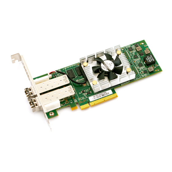
1–Product Overview Hardware Components Figure 1-3, the FCoE adapter communicates to existing native Fibre Channel storage because of the translation capability of the switch. Figure 1-3. FCoE Deployment Hardware Components A typical 8100 Series Adapter has the following major components ... -
Page 36: Series Adapter Components
1–Product Overview Hardware Components Figure 1-4 shows the hardware components of a QLogic 8100 Series Adapter. Table 1-3 describes the 8100 Series Adapter components. Figure 1-4. 8100 Series Adapter Components Table 1-3. 8100 Series Adapter Components Hardware Function Component ASIC The Converged Network Controller, also known as the intelligent storage peripheral (ISP) controller, is the heart of the adapter. -
Page 37: Overview
Each transceiver is a removable device that functions both as trans- mitter and as a receiver. A transceiver and cable connect the adapter to other devices. A transceiver can be a QLogic-branded SR (short range), optical transceiver, or copper cables. For a list of QLogic approved copper cables, visit http://www.qlogic.com/Resources/Pages/Resources.aspx... -
Page 38: Boot Code
(PXE) boot server attached to the QLogic Converged Network Adapter. This type of configuration is called PXE boot (LAN) or boot from SAN. QLogic Converged Network Adapters support PXE boot for servers with BIOS and unified extensible firmware interface (UEFI) capabilities, and boot from SAN for servers with BIOS, UEFI, and FCode capabilities. -
Page 39: Firmware
CPU and memory resources from protocol processing. This efficiency saves runtime system resources, such as CPU and memory. For the QLogic 8100 Series Adapter, the firmware comes as part of the multi-boot image, which comprises the boot code, FCoE firmware, message passing interface (MPI) firmware, and various offline utilities. - Page 40 ETS, port-level statistics, Fibre Novell SLES Channel support quality of service QConvergeConsole (QoS), N_Port ID virtualization (NPIV), and FCAPS capabilities. QLogic SuperIn- Windows Windows utility that installs: staller for Windows FC-FCoE and Ethernet Network- ing (NDIS) drivers. VLAN and Teaming driver.
- Page 41 1–Product Overview Hardware Components Table 1-4. Software and Firmware Components (Continued) Operating System Component Comments (QLogic Supported QLogic SuperIn- Red Hat RHEL Linux Utility that installs: staller for Linux Novell SLES FC-FCoE and Ethernet Network- ing drivers. QConvergeConsole command line interface (CLI) Management Tool.
-
Page 42: Adapter Specifications
PCIe Gen 1 x8 mode, 250MBps per lane PCIe Gen 2 x4 mode, 500MBps per lane QLogic adapters can automatically train a PCIe Gen 2 x8 slot to use the slot as a PCIe Gen 2 x4 slot, where four lanes of the PCIe Gen 2 x8 slot are powered off to save power and maximize performance. -
Page 43: Transceiver Requirements
QLogic-approved active copper cables only. Refer http://www.qlogic.com/Products/CU_Cables.aspx for a list of approved cables from switch vendors. The adapter port will function; however, QLogic provides no warranty or technical support for this configuration. The adapter port will not function. Table 1-7. FCoE Specifications... -
Page 44: Ethernet Specifications
1–Product Overview Adapter Specifications Table 1-7. FCoE Specifications (Continued) Feature Description N_Port ID Supports 256 virtual ports per physical port, optimized for Virtualization virtualization Topology Support Point-to-point and switched fabric Logins Supports 2,048 concurrent logins and 2,048 concurrent exchanges Boot from SAN Supports booting the server with an operating system that resides on the SAN instead of on a local hard disk drive Class of Service... - Page 45 1–Product Overview Adapter Specifications Table 1-8. Ethernet Specifications (Continued) Specification Description Compliance IEEE: 802.3ae (10Gb Ethernet) 802.1q (VLAN) 802.3ad (Link Aggregation) 802.1p (Priority Encoding) 802.3x (Flow Control) IEEE 1149.1 (JTAG) IPv4 Specification (RFC 791) ...
-
Page 46: Management Specifications
qlremote and netqlremote—Agent software that allows the remote management of QLogic adapters with the QConvergeConsole web management interface. QLogic FC HBA API—SNIA HBA API V2 - Management API for integration with other tools. SNIA Common Adapter API—v1.x/v2.0 compliant. -
Page 47: Management Tools
Management Tools Overview QLogic provides the following tools with which to manage the QLogic 8100 Series Converged Network Adapter: QConvergeConsole Web Management GUI QConvergeConsole Management Agents (qlremote/netqlremote) QConvergeConsole CLI Offline Utilities QConvergeConsole Web Management GUI The QConvergeConsole management tool is a Web-based client/server application that allows for centralized management and configuration of QLogic adapters within the entire network (LAN and SAN) via a Graphical User Interface. -
Page 48: Qconvergeconsole Management Agents (Qlremote/Netqlremote)
Configuration management – QConvergeConsole allows you to configure local and remote systems. With QConvergeConsole you can configure QLogic adapters and connected devices. It also lets you update adapter parameters, firmware, boot code, and drivers. NOTE: You can install the adapter driver before you install the adapter hardware. -
Page 49: Qconvergeconsole Cli
You can automate management and monitoring tasks using scripts. You must install the CLI on the host in which the QLogic adapter is installed. The CLI manages only the host on which it is installed. The CLI is also available as a menu interface. - Page 50 EFICFG—This utility provides a UEFI shell into the server manufacturer’s boot-up menu interface, which configures advanced adapter features, including boot-from-SAN. EFIUTIL—This utility installs the multi-boot image (including firmware) on the QLogic Converged Network Adapter. For more information about the offline utilities, refer to Section FE0254601-00 A...
-
Page 51: Installation In A Windows Environment
Windows Server 2008 Server Core Architecture Support: IA-32 (x86), Intel64, AMD64 (x64) Refer to the Read Me file provided with the QLogic 8100 Series Adapter multi-flash image or Windows driver for a complete list of supported operating systems and required service packs. -
Page 52: Cabling Requirements
QLogic 8100 Series Adapter drivers are not included with most versions of Microsoft Windows operating systems. Microsoft Windows does not recognize the QLogic 8100 Series Adapter until the drivers are installed on the server. If the adapter drivers are installed on the server, go to... -
Page 53: Select An Adapter And A Windows Operating System
3–Installation in a Windows Environment Downloading QLogic Drivers In the selection list, click Converged Network Adapters in the first column. In the selection list, click on the adapter model number in the second column. In the third column, click the version of the Microsoft Windows operating system that is installed on the server. -
Page 54: Installing Hardware
3–Installation in a Windows Environment Installing Hardware Under Drivers, click the download link for the QLogic drivers. To enable all adapter capabilities, download both the FCoE (STOR Miniport) and NIC (NDIS Miniport) drivers (Figure 3-2). Figure 3-2. Download Drivers for Windows Servers Read the QLogic license agreement, and then click Agree. -
Page 55: Install The Adapter
Record the adapter model number, which can be found on the bar code label on the board. Determine whether the server requires a full-height or a half-height adapter bracket. The QLogic 8100 Series Adapter ships with a full-height bracket installed and a spare half-height (low profile) bracket. To install the half-height bracket: Using the bail handle of the SFP+ transceivers, pull out the SFP+ modules. -
Page 56: Verify The Adapter Installation
PCIe device, and it is safe to boot the operating system and install the QLogic driver. The presence or absence of the QLogic banner does not indicate that the QLogic adapter has been connected to a compatible switch. FE0254601-00 A... -
Page 57: Installing Software
SAN” on page 7-15. For unified extensible firmware interface (UEFI) servers, boot into the UEFI shell and enter the drivers command to verify that the QLogic adapter is in the list of discovered devices. Figure 3-4 shows sample output for a dual-port QLogic 8100 Series Adapter. -
Page 58: Creating The Driver Disk Or Extracting The Driver File Into A Folder
3–Installation in a Windows Environment Installing Software CAUTION! A reboot may be required to complete the installation of a QLogic driver. If a reboot is required, the driver installation process prompts for a reboot. NOTE: For Microsoft Windows 2003 operating systems, a Microsoft STOR miniport update is required before installing the FCoE driver. -
Page 59: Device Properties
3–Installation in a Windows Environment Installing Software To obtain vendor ID and device ID information: Right-click on the My Computer icon on the desktop or in the Start menu, and then select Manage. Select Device Manager in the left pane. In the right pane, under Other Devices, right click on any device and click Properties (Figure... -
Page 60: Installing And Updating Drivers Using Device Manager
In the Property drop-down list, select Device Instance Id (Windows Server 2003) or Hardware Ids (Windows 2008). Figure 3-6 shows sample vendor IDs and device IDs for QLogic 8100 NIC adapter (Windows 2003) and QLogic 8100 FCoE adapter (Windows 2008). QLogic 8100 NIC QLogic 8100 FCoE... -
Page 61: Qlogic 8100 Series Adapter Device Entries
In the Computer Management window, select Device Manager in the left pane. Scroll down the list of hardware types in the right pane. If you are installing the QLogic adapter drivers for the first time on this server, do the following; otherwise, go to Step Click Other Devices to see a list of devices for which a driver is not installed on the server. -
Page 62: Typical Qlogic 8100 Series Ethernet Adapter Port Entries
Adapter under this section. Figure 3-9 shows typical entries for a dual-port QLogic 8100 Series Adapter. Figure 3-9. Typical QLogic 8100 Series Ethernet Adapter Port Entries To update the driver, right click Ethernet Controller, and then click Update Driver (Figure 3-10). -
Page 63: Starting The Hardware Update Wizard
QLogic NIC driver that you downloaded in “Downloading QLogic Drivers” on page 3-2. Select the setup information file (qlge.inf) from the list of QLogic NIC driver files, and then click Open. When the Hardware Update Wizard/Select a Device Driver dialog box opens, click Next. -
Page 64: Installing The Fcoe Driver For Windows Server 2003
In the Computer Management window, select Device Manager in the left pane. Scroll down the list of hardware types in the right pane. If you are installing the QLogic adapter drivers for the first time on this server, do the following; otherwise, go to Step Click Other Devices to see a list of devices for which a driver is not installed on the server. -
Page 65: Installing An Fcoe Driver
Figure 3-14. Installing an FCoE Driver If you are updating QLogic adapter drivers: Click SCSI and RAID Devices (for FCoE Drivers). Find each port of the QLogic adapter FCoE function that is listed as QLogic FCoE Adapter under this section. Figure 3-15 shows typical entries for a dual-port QLogic 8100 Series Adapter. -
Page 66: Updating An Fcoe Driver
Select the setup information file (qlfcoe.inf) from the list of QLogic FCoE driver files, and then click Open. When the Hardware Update Wizard/Select a Device Driver dialog box opens, click Next. Confirm that the QLogic FCoE adapter is shown in the list of network adapters (Figure 3-17), and then click Next. -
Page 67: Installing The Nic Driver For Windows Server 2008
In the Server Management window, expand the Diagnostics entry in the left pane, and then select Device Manager. Scroll down the list of hardware types. If you are installing the QLogic adapter drivers for the first time on this server, do the following; otherwise go... -
Page 68: Installing An Nic Driver—Windows 2008
Figure 3-19. Installing an NIC Driver—Windows 2008 If you are updating QLogic adapter drivers: Click Network Adapters (for NIC drivers). Find each port of the QLogic adapter NIC function that is listed as QLogic10Gb PCI Ethernet Adapter under this section. Figure 3-20 shows typical entries for a dual-port QLogic 8100 Series Adapter. -
Page 69: Starting The Update Driver Software Wizard
Figure 3-22. Starting the Update Driver Software Wizard In the Update Driver Software–Ethernet Controller dialog box, click Browse, and then navigate to the folder containing the QLogic NIC driver that you downloaded earlier. Click Next. Figure 3-23. Select Driver Software The Microsoft Windows Update Driver Software Wizard installs the NDIS driver for the QLogic adapter NIC function. -
Page 70: Installing The Fcoe Driver For Windows Server 2008
In the Server Management window, expand the Diagnostics entry in the left pane, and then select Device Manager. Scroll down the list of hardware types. If you are installing the QLogic adapter drivers for the first time on this server, do the following; otherwise go... -
Page 71: Installing An Fcoe Driver For Windows 2008
Figure 3-26 shows typical entries for a dual-port QLogic 8100 Series Adapter. Figure 3-26. Typical QLogic 8100 Series Adapter Port Entry To update the driver, right click QLogic FCoE Adapter, and then click Update Driver Software… (Figure 3-27). Figure 3-27. Updating an FCoE Driver for Windows 2008... -
Page 72: Select Driver Software
(Figure 3-28). Figure 3-28. Starting the Update Driver Software Wizard In the Update Driver Software–Ethernet Controller dialog box, click Browse, and then navigate to the folder containing the QLogic FCoE driver that you downloaded earlier (Figure 3-29). Click Next. Figure 3-29. Select Driver Software The Microsoft Windows Update Driver Software Wizard proceeds to install the FCoE driver for the QLogic adapter FCoE function. -
Page 73: Installing And Updating Drivers Using The Windows Superinstaller
QConvergeConsole CLI utility installation Downloading the Windows SuperInstaller To download the Windows SuperInstaller: Go to the QLogic Web site: http://driverdownloads.qlogic.com. Click QLogic Products. Click QLogic Adapters. In the selection list, click Converged Network Adapters in the first column. In the selection list, click the adapter model number in the second column. -
Page 74: Download The Windows Superinstaller
3-32). On the same page, review the Readme file, which describes how to install and use the Windows SuperInstaller. The release notes provide the versions of the QLogic adapter drivers that are bundled with the SuperInstaller. Figure 3-32. Download the Windows SuperInstaller Read the license agreement that opens, then click I Agree to accept the terms. -
Page 75: Initial Windows Server 2003 Installation With The Converged Network Adapter As Boot Device (For Fcoe Driver Only)
After all drivers have been loaded for the standard devices (Figure 3-33), type S to select Specify Additional Device. Figure 3-33. Specify Additional Device Insert the QLogic driver disk (3.5-inch floppy) into a floppy disk drive on the server, and then press ENTER (Figure 3-34). FE0254601-00 A... -
Page 76: Insert Driver Disk
CD-ROMs; therefore, a 3.5-inch disk is required. Figure 3-34. Insert Driver Disk Windows displays a list of drivers found on the disk (Figure 3-35). Select QLogic FCoE Adapter, and then press ENTER. Figure 3-35. Select QLogic FCoE Adapter 3-26 FE0254601-00 A... -
Page 77: Initial Windows Server 2008 Installation With The Converged Network Adapter As Boot Device (For Fcoe Driver Only)
Figure 3-36. Install Additional Drivers Continue with the standard Windows Server 2003 installation procedure. For more information about the other QLogic BIOS configurations required to enable a server to boot from SAN, refer to “Boot from SAN” on page 7-15. -
Page 78: Windows Installation Type
3–Installation in a Windows Environment Installing Software When prompted to indicate the type of installation (Figure 3-37), click Custom (advanced). Figure 3-37. Windows Installation Type When prompted to indicate where to install Windows (Figure 3-38), click Load Driver. Figure 3-38. Windows Installation Location 3-28 FE0254601-00 A... -
Page 79: Insert The Driver Disk
3-39), insert the QLogic driver disk (3.5-inch disk, USB memory stick, CD/DVD-ROM), click Browse, and then select the drive containing the QLogic driver disk. Figure 3-39. Insert the Driver Disk Windows Setup presents a list of all drivers on the driver disk (Figure 3-40). -
Page 80: Removing The Driver
3–Installation in a Windows Environment Removing the Driver Windows loads the QLogic FCoE driver, and displays all LUNs that were presented to the QLogic adapter for a boot-from-SAN installation. If LUNs are found, Windows prompts you to select the disk/LUN on the SAN on... -
Page 81: Verifying Driver Installation
Adapters and Storage Controllers sections are expanded. Figure 3-42. Confirming Port Classification and Health Verify that QLogic adapter driver versions are the most recent for the server operating system. Compare the installed driver versions with those on the QLogic Web site. For information about downloading drivers from the QLogic Web site, see “Downloading QLogic Drivers”... -
Page 82: Network Adapters And Storage Controllers
NIC adapter driver (version 1.0.1.0) and an FCoE adapter driver (version 9.1.8.26). Figure 3-44. NIC and FCoE Adapter Driver Properties Understand the LED scheme for QLogic 8100 Series Adapters. For information about QLogic 8100 Series Adapter LEDs, see Appendix... -
Page 83: Firmware Upgrades
QLogic 8100 Series Converged Network Adapters ship with the latest firmware version. QLogic periodically releases new firmware versions, which can be downloaded from the QLogic Web site as part of a multi-boot image. Always use the latest firmware versions for enhanced performance and availability. -
Page 84: Determining The Installed Firmware Version
Determining the Installed Firmware Version Use the QConvergeConsole GUI or QConvergeConsole CLI to determine the firmware version of the QLogic adapter installed in the server. For information about installing and using the QConvergeConsole management tools, refer to Section... -
Page 85: Displaying The Adapter Firmware Version
In the QConvergeConsole web management GUI, in the left pane, expand the host to view the connected adapters. Select the port QLogic 8100 Series Adapter for which to determine the installed firmware version. The HBA Info tabbed page identifies the... -
Page 86: Upgrading The Firmware/Boot Code
3–Installation in a Windows Environment Firmware Upgrades Expand the physical Port 1, select the FCoE port, and then select the VPD (Figure 3-48) in the right pane. The Flash Image Version appears at the bottom of the Port Vital Product Data (VPD) list. Figure 3-48. -
Page 87: Qconvergeconsole—Update Entire Image
3–Installation in a Windows Environment Firmware Upgrades Under Flash, click Update Entire Image (Figure 3-52). Figure 3-49. QConvergeConsole—Update Entire Image Click the Choose File button. The Open dialog box appears. Navigate to and click on the file from which to update, then click Open. Make sure you select the correct file. -
Page 88: Updating Firmware Using Qlogic Bios And Uefi Utilities
Firmware Version” on page 3-34. For information about using QLogic offline utilities, see Section Installing Management Tools QLogic 8100 Series Adapters can be managed with QLogic tools requiring a separate installation, or with built-in Microsoft Windows tools. The QLogic tools are: QConvergeConsole... -
Page 89: Obtaining Qlogic Adapter Management Utilities
Obtaining QLogic Adapter Management Utilities To download the QLogic management utilities and documentation: Go to the QLogic Web site: http://driverdownloads.qlogic.com. Click QLogic Products. In the selection box... -
Page 90: Installing And Launching The Qconvergeconsole
QConvergeConsole is installed or remotely from another computer. From the main window, you can connect to servers that host QLogic adapters and devices you want to manage. NOTE: Refer to the QConvergeConsole User’s Guide and the online help system for more details. -
Page 91: Install The Qconvergeconsole: Install Tomcat On Your System
3–Installation in a Windows Environment Installing Management Tools Click Next. If the Apache Tomcat server is not installed, a message prompts whether you want to install Tomcat on your system (Figure 3-52). Figure 3-52. Install the QConvergeConsole: Install Tomcat on Your System Click Yes. -
Page 92: Install The Qconvergeconsole: Installation Status
3–Installation in a Windows Environment Installing Management Tools During the installation, the installer notifies you of the installation status (Figure 3-54). Figure 3-54. Install the QConvergeConsole: Installation Status A message prompts you to confirm that you want to enable the Secure Socket Layer (SSL) feature, which allows you to run QConvergeConsole in a secured environment (Figure... -
Page 93: Install The Qconvergeconsole: Install Complete Notification
These agents can be installed using the Windows SuperInstaller found on the download sections for your specific adapter at http://driverdownloads.qlogic.com. Open QConvergeConsole locally on the server or from a remote computer. To open QConvergeConsole locally on the server:... -
Page 94: Qconvergeconsole Resides
3–Installation in a Windows Environment Installing Management Tools Figure 3-57. QConvergeConsole Main Window on the Server Where QConvergeConsole Resides To open QConvergeConsole from a remote computer: Enter the IP address of the QConvergeConsole server, followed by the access port and application name in the browser's address bar using the following format: http://xxx.xxx.xxx.xxx:8080/QConvergeConsole/ In the following example, the Web address of the QConvergeConsole server... -
Page 95: Entering Qconvergeconsole Web Address (Example)
3–Installation in a Windows Environment Installing Management Tools Figure 3-58. Entering QConvergeConsole Web Address (Example) The initial main menu of the QConvergeConsole opens, as shown in Figure 3-59. Figure 3-59. QConvergeConsole Main Window from a Remote Computer —Unpopulated View FE0254601-00 A 3-45... -
Page 96: Installing And Launching The Qconvergeconsole Cli
QCCCLI.msi msiexec /i QCCCLI.msi The default directory for the QConvergeConsole CLI application is: Program files\QLogic Corporation\QCCCLI If you want a different directory, type it in the command line. For example: QCCCLI.msi installdir="directory" The preceding command installs the QConvergeConsole CLI in the directory named directory. -
Page 97: Overwrite Previous Windows Installations
Type the following for an installation that overwrites any previous installations without asking for confirmation. Type: QCCCLI.msi /i forceinstall=true Starting the QConvergeConsole CLI You can start the QLogic 8100 Series Converged Network Adapter in Windows in the following ways: Double click the QCCCLI icon on the desktop. - Page 98 3–Installation in a Windows Environment Installing Management Tools 3-48 FE0254601-00 A...
-
Page 99: Installation In A Linux Environment
Installation in a Linux Environment Overview This section describes how to install a QLogic 8100 Series Adapter in a Linux server, including system requirements, hardware installation, driver installation, and software installation. System Requirements Operating System Requirements The QLogic 8100 Series Adapter supports the following Linux operating systems: ... -
Page 100: Cabling Requirements
The server motherboard must have a PCIe slot of at least x8 physical length. Both PCIe Gen 1 and Gen 2 slots are supported. QLogic adapters operate on all eight lanes on a PCIe Gen 1 x8 slot, and automatically train down to use only four lanes on a PCIe Gen 2 x8 slot, thus saving energy by powering off the remaining four lanes of the PCIe Gen 2 x8 slot. -
Page 101: Install The Adapter
Record the adapter model number, which can be found on the bar code label on the board. Determine whether the server requires a full-height or a half-height adapter bracket. The QLogic 8100 Series Adapter ships with a full-height bracket installed and a spare half-height (low profile) bracket. To install the half-height bracket: Using the bail handle of the SFP+ transceivers, pull out the SFP+ modules. -
Page 102: Adapter Hardware
4–Installation in a Linux Environment Installing Hardware Connect the other end of the Ethernet cable to a supported switch. Plug in the power cables and power up the server. Figure 4-1. Adapter Hardware FE0254601-00 A... -
Page 103: Drivers Command Output
“Boot-from-SAN” on page 8-29. For unified extensible firmware interface (UEFI) servers, boot into the UEFI shell and enter the Drivers command to verify that the QLogic adapter is in the list of discovered devices. Figure 4-2 shows sample output for a dual-port QLogic 8100 Series Adapter. -
Page 104: Installing Software
Close any open windows of the QConvergeConsole before proceeding with the driver installation. CAUTION! A reboot may be required to complete the installation of a QLogic driver. If a reboot is required, the driver installation process prompts for a reboot. Installing the FCoE Driver (qla2xxx) The QLogic 8100 Series Adapter FCoE drivers are included (inbox or in kernel) with all supported versions of RHEL 5, except RHEL 5.3. -
Page 105: Select An Adapter And A Linux Operating System
Read the QLogic license agreement, and then click Agree. When prompted, click Save to save the compressed driver file to a temporary location on the hard drive. The compressed file contains the source for the QLogic FC-FCoE drive. The file name has the following format: qla2xxx-src-x.xx.xx.xx.xx.xx-k.tar.gz... -
Page 106: Compiling The Qlogic Driver
-ivh gcc-4.1.2-46.el5.x86_64.rpm Figure 4-5 shows the response to the first two commands. Figure 4-5. Compiling the QLogic Driver You can also use the yum command to compile these packages. For more information about the yum command, refer to the manual pages. -
Page 107: Executing The Build.sh Script
Execute the build.sh script to compile the driver modules from the source code. # ./extras/build.sh install The build.sh script does the following: Builds the QLogic FCoE driver .ko files. Copies the .ko files to the appropriate /lib/modules/2.6.<kernel-sub-version>/extra/qlgc-ql a2xxx directory. - Page 108 # modprobe –r qla2xxx The following error message indicates that the unload operation failed because the server is engaged in I/O operations through the QLogic adapter, or another module is dependent on the qla2xxx module. FATAL: Module qla2xxx is in use In this case, stop all I/O, eliminate dependent modules, and unload the module again.
-
Page 109: Installing The Fcoe Driver For Rhel 5.3 Boot-From-San
Installing Software Installing the FCoE Driver for RHEL 5.3 Boot-from-SAN The RHEL 5.3 operating system does not include the QLogic 8100 Series Adapter drivers. Therefore, to boot from SAN, you must load the adapter drivers during the operating system installation. QLogic provides a driver disk kit (DD-Kit) for RHEL 5.3 that contains the driver binaries for RHEL 5.3. -
Page 110: Download The Fc-Fcoe Dd-Kit
Read the QLogic license agreement, and then click Agree. When prompted, click Save to save the driver file to the hard drive. The compressed file contains the source for the QLogic FC-FCoE driver. The file name has the following format: qla2xxx-src-x.xx.xx.xx.xx.xx-k.tar.gz... -
Page 111: Rhel 5.3 Boot Screen
4–Installation in a Linux Environment Installing Software Configure the server to boot from the optical drive, and power up the server. The system boots from the CD and stops at the boot: prompt (Figure 4-9). Figure 4-9. RHEL 5.3 Boot Screen At the boot: prompt, press the F2. -
Page 112: Installing The Networking Driver
ENTER. At the Insert Driver Disk window, insert the driver disk into the appropriate drive, click OK, and then press ENTER. The QLogic driver is loads automatically from the driver disk. The Disk Driver window prompts you to install more drivers. Click NO, and then press ENTER. -
Page 113: Download The Networking Driver
Read the QLogic license agreement, and then click Agree. When prompted, click Save to save the compressed driver file to a temporary location on the hard drive. The compressed file contains the source for the QLogic networking driver. The file name has the following format: qlge_x.x.x.xx-ddmmyy_xx_x.x.xx.tgz... - Page 114 4–Installation in a Linux Environment Installing Software Insert the RHEL 5 installation DVD into the optical drive on the server, or into another drive that contains the following packet files for the RHEL 5 version and architecture installed on the server. ...
-
Page 115: Make Install Command Execution Log
Build and install the driver modules from the source code. # make install The GNU executes the makefile included in the qlge/ directory and then does the following: Builds the QLogic networking driver .ko files Copies the .ko file to the appropriate /lib/modules/[Kernel_version]/kernel/drivers/net/ql ge/ directory. - Page 116 # modprobe –r qlge The following error message indicates that the unload operation failed because the server is engaged in I/O operations through the QLogic adapter, or another module is dependent on the qlge module. FATAL: Module qlge is in use In this case, stop all I/O, eliminate dependent modules and unload the module again.
-
Page 117: Verifying The Driver Installation
# lsmod | grep qlgc # qlge 129881 Verify the QLogic adapter driver versions. You can use sysfs (FCoE) and ethtool (networking), which is usually the most accurate. You can also use the modinfo command. The following example displays the FCoE driver version, where X is ... -
Page 118: Removing Drivers
For specific LED indications, refer to Appendix Removing Drivers Uninstalling the QLogic FCoE or networking driver disables the adapter and terminates communication between the server and connected SAN or LAN devices. In a boot-from-SAN configuration, the FCoE driver (qla2xxx) cannot be uninstalled because the server accesses the operating system image over the SAN through the adapter. -
Page 119: Firmware Upgrades
QLogic 8100 Series Converged Network adapters ship with the latest available firmware version. QLogic periodically releases new firmware versions, which can be downloaded from the QLogic Web site as part of a multi-boot image. Always use the latest firmware versions for enhanced performance and availability. -
Page 120: Determining The Installed Firmware Version
You can determine the firmware version the QConvergeConsole, or for advanced users, sysfs. Displaying the Firmware Version Using the QConvergeConsole Use QConvergeConsole GUI or QConvergeConsole CLI to determine the firmware version of the QLogic adapter installed in the server. For information about installing and using QConvergeConsole, refer to Installing Software. -
Page 121: Displaying The Adapter Firmware Version
NOTE: Ignore the driver firmware version listed under Information; it is not related to the installed adapter firmware version. QLogic 8100 Series Adapter drivers are not bundled with the firmware, and use the firmware that is resident on the adapter hardware. -
Page 122: Displaying The Firmware Version Using Sysfs
4–Installation in a Linux Environment Firmware Upgrades In the right pane, click the FCoE tab (Figure 4-17). The MPI firmware version is listed under the Information section. Figure 4-17. Displaying the Adapter MPI Firmware Version Displaying the Firmware Version Using sysfs The sysfs interface is available to advanced users to display the adapter firmware version. -
Page 123: Qconvergeconsole—Update Entire Image
4–Installation in a Linux Environment Firmware Upgrades Under Flash, click Update Entire Image (Figure 4-18). Figure 4-18. QConvergeConsole—Update Entire Image In the Open pop-up window, browse to the temporary folder that contains the extracted multi-boot image, and then select the Flash file (.BIN). Click Open. -
Page 124: Using Qlogic Bios And Uefi Utilities
For information about using QLogic offline utilities, refer to Section Management Tool Installation QLogic 8100 Series Adapters can be managed with QLogic utilities or with Linux utilities. The QLogic utilities are: QConvergeConsole web management GUI, which is used to configure and manage QLogic Fibre Channel adapters, Intelligent Ethernet Adapters, and Converged Network Adapters within storage area networks (SANs). -
Page 125: Obtaining The Qlogic Adapter Management Tools
In the third column, click the Linux operating system that is installed on the server, and then click Go. Under Management Tools, click the download link for the QLogic management application that you want, including the Readme and Release Note files (Figure 4-19). -
Page 126: Installing And Launching Qconvergeconsole
4–Installation in a Linux Environment Management Tool Installation Installing and Launching QConvergeConsole To install and launch the QConvergeConsole: QConvergeConsole can be installed on a Linux host by running a Virtual Network Computing (VNC ) program on a Windows host to remotely control the ®... -
Page 127: Install The Qconvergeconsole: Installer Extracts Files
4–Installation in a Linux Environment Management Tool Installation Click Run in Terminal. The installer extracts the files and installs QConvergeConsole in the directory /opt/QConvergeConsole_Installer (Figure 4-23). Figure 4-23. Install the QConvergeConsole: Installer Extracts FIles The InstallAnywhere window prepares to install the QConvergeConsole and opens the installation Introduction dialog box (Figure 4-24). -
Page 128: Install The Qconvergeconsole: Pre-Installation Summary
4–Installation in a Linux Environment Management Tool Installation The Pre-Installation Summary dialog box (Figure 4-25) opens. Figure 4-25. Install the QConvergeConsole: Pre-Installation Summary Read the information, and then click Install. 4-30 FE0254601-00 A... -
Page 129: Install The Qconvergeconsole: Installation Status
4–Installation in a Linux Environment Management Tool Installation During the installation, the installer notifies you of the installation status (Figure 4-26). Figure 4-26. Install the QConvergeConsole: Installation Status FE0254601-00 A 4-31... -
Page 130: Install The Qconvergeconsole: Install Complete Notification
These agents can be installed using the Linux SuperInstaller found on the download sections for your specific adapter at http://driverdownloads.qlogic.com. Open QConvergeConsole locally on the server or from a remote computer. To open QConvergeConsole locally on the server:... -
Page 131: Qconvergeconsole Resides
4–Installation in a Linux Environment Management Tool Installation Figure 4-28. QConvergeConsole Main Window on the Server Where QConvergeConsole Resides To open QConvergeConsole from a remote computer: Enter the IP address of the QConvergeConsole server, followed by the access port and application name in the browser's address bar using the following format: http://xxx.xxx.xxx.xxx:8080/QConvergeConsole/ In the following example, the Web address of the QConvergeConsole server... -
Page 132: Unpopulated View
4–Installation in a Linux Environment Management Tool Installation Figure 4-29. Entering QConvergeConsole Web Address (Example) The initial main menu of the QConvergeConsole opens, as shown in Figure 4-30. Figure 4-30. QConvergeConsole Main Window from a Remote Computer —Unpopulated View 4-34 FE0254601-00 A... -
Page 133: Installing And Launching The Qlogic Linux Tools
Sets the timeout on the devices connected to the ql-set-cmd-timeout-x.x.tgz QLogic Fibre Channel adapter To install and launch the QLogic Linux utilities on the RHEL 5 host: Extract the component files from the Linux-Tools-yyyymmdd-x.tgz file by typing the following command: # tar –xvzf Linux-Tools-yyyymmdd-x.tgz... - Page 134 4–Installation in a Linux Environment Management Tool Installation Table 4-2. QLogic Linux Utility Directories and Commands Directory Command ql-hba-snapshot-x.xx/ ./ql-hba-snapshot.sh ql-lun-state-online-x.x/ ./ql-lun-state-online.sh –i ql-set-cmd-timeout-x.x/ ./ql-set-cmd-timeout.sh -i For information about using the Linux utilities, refer to “Using the QLogic Linux Utilities” on page 8-41.
-
Page 135: Installation In A Vmware Environment
Installation in a VMware Environment Overview This section describes how to install a QLogic 8100 Series Adapter in VMware ® ESX/ESXi environments including, hardware installation, driver installation, and software installation. Installing Hardware CAUTION! To minimize the risk of ESD damage, use a workstation anti-static mat and an ESD wrist strap. - Page 136 Plug the appropriate Ethernet cable (either copper or optical) into the adapter. QLE814x adapters ship with optical transceivers already installed. 814x adapters operate only with optical transceivers sold by QLogic. For QLE815x adapters, see the list of approved copper cables at http://www.qlogic.com/Resources/Pages/Resources.aspx under Cable Support.
-
Page 137: Installing The Fcoe And Networking Drivers
LED indications, refer to Appendix Installing the FCoE and Networking Drivers The QLogic 8100 Series Adapter driver is not included with the VMware ESX™/ESXi4.0 operating system. Therefore, you must download the drivers for VMware ESX/ESXi 4.0 from the QLogic Web site at http://driverdownloads.qlogic.com/. -
Page 138: Select Adapter Software For Vmware By Operating System
5–Installation in a VMware Environment Installing the FCoE and Networking Drivers Select VMware ESX/ESXi in the third column of the selection list, and then click Go (Figure 5-2). Figure 5-2. Select Adapter Software for VMware by Operating System In the Drivers table, click the links that correspond to the following descriptions to download the drivers: ... -
Page 139: Selecting The Summary Tab
5–Installation in a VMware Environment Installing the FCoE and Networking Drivers On the ESX host server, in maintenance mode, select the Summary tab (Figure 5-4). Figure 5-4. Selecting the Summary Tab Right-click the storage icon, and then select Browse Datastore (Figure 5-5). -
Page 140: Creating A Temporary Folder In Which To Store The Driver Iso Files
5–Installation in a VMware Environment Installing the FCoE and Networking Drivers In the Datastore Browser, create a temporary folder in which to store the driver ISO files (Figure 5-6). Figure 5-6. Creating a Temporary Folder in Which to Store the Driver ISO Files Click the Upload icon to upload the driver ISO files into the temporary folder (Figure 5-7). - Page 141 5–Installation in a VMware Environment Installing the FCoE and Networking Drivers Change to the directory that contains the driver ISO files by issuing the following command: # cd /vmfs/volumes/Storage1/<esxconsole>/temp Mount the first ISO file under the ESX host server by issuing the following command: # mount -o loop –t iso9660 <network driver file>.iso /mnt/cdrom...
-
Page 142: Verifying Driver Installation
# ls /proc/scsi: If the qla2xxx directory is present, the QLogic FCoE adapter driver is installed on the VMware ESX/ESXi 4.0 host server. List the QLogic FCoE adapters present on the ESX host server by issuing the following command: # ls /proc/scsi/qla2xxx... -
Page 143: Displaying Fcoe Adapter Driver Details
FCoE adapter 3, including the current state, the firmware version, the driver version, and the boot code version. Figure 5-10. Displaying FCoE Adapter Driver Details List details for the QLogic adapter networking driver by issuing the following command: ifconfig -a The example in... -
Page 144: Displaying Networking Adapter Driver Details
5–Installation in a VMware Environment Installing the FCoE and Networking Drivers Figure 5-11. Displaying Networking Adapter Driver Details 5-10 FE0254601-00 A... -
Page 145: Identifying Qlogic Adapters Using Vsphere Client
Display adapter networking driver and firmware versions for QLogic vmnic interfaces by issuing the following command: # ethtool –i vmnic[N] In this command, [N] is the adapter number that corresponds to a QLogic interface from the ifconfig –a display (Figure 5-11). -
Page 146: Configuring Nic Using The Vsphere Client
5–Installation in a VMware Environment Configuring NIC Using the vSphere Client Figure 5-13. Displaying Storage Adapters Using the vSphere Client In the Hardware pane, select Network Adapters to display all network adapters, as shown in Figure 5-14. Figure 5-14. Displaying Network Adapters Using the vSphere Client Configuring NIC Using the vSphere Client To configure the NIC using the vSphere client: Ensure that the necessary guest operating systems have been installed on... -
Page 147: Configuring Networking Adapters
5–Installation in a VMware Environment Configuring NIC Using the vSphere Client Open the vSphere client, and then click the Configuration tab. In the Hardware pane, select Networking, as shown in Figure 5-15. Figure 5-15. Configuring Networking Adapters Select Add Networking . . in the upper right portion of the window. In the Add Network Wizard, click Virtual Machine, and then click Next (Figure 5-16). -
Page 148: Selecting The Virtual Switch
5–Installation in a VMware Environment Configuring NIC Using the vSphere Client Click the vmnic associated with the QLogic adapter to be connected to the new virtual switch, and then click Next. Figure 5-17. Selecting the Virtual Switch Modify the network label and VLAN ID if needed, and then click Next (Figure 5-18). -
Page 149: Configuring The Driver Parameters
Click Finish to complete the addition of the networking interface. Configuring the Driver Parameters Use the esxcfg-module command to configure the QLogic Fibre Channel and Converged Network Adapter driver parameters. Configuration changes made using the esxcfg-module -s command are preserved across system reboots. -
Page 150: Esxcfg-Module Configurable Driver Parameters
5–Installation in a VMware Environment Configuring the Driver Parameters Reboot the server to place the parameter changes into effect. # reboot Table 5-1 describes the configurable QLogic driver parameters. Table 5-1. esxcfg-module Configurable Driver Parameters Driver Parameter Description ql2xallocfwdump Enables (1) or disables (0) allocation of memory for a firmware dump during adapter initialization. - Page 151 5–Installation in a VMware Environment Configuring the Driver Parameters Table 5-1. esxcfg-module Configurable Driver Parameters (Continued) Driver Parameter Description ql2xplogiabsentdevice Enables (1) or disables (0) PLOGI (port login) to devices that are not present after a fabric scan. Enabling this parameter is required to work around some Fibre Channel switch defects.
-
Page 152: Configuring A Hard Drive In A Virtual Machine
5–Installation in a VMware Environment Configuring a Hard Drive in a Virtual Machine Configuring a Hard Drive in a Virtual Machine To configure a hard drive in a virtual machine: Open vSphere and exit maintenance mode on the vSphere client (Figure 5-19). -
Page 153: Virtual Machine Properties Window
5–Installation in a VMware Environment Configuring a Hard Drive in a Virtual Machine Click Add in the Virtual Machine Properties window to add a device to the virtual machine (Figure 5-21). Figure 5-21. Virtual Machine Properties Window FE0254601-00 A 5-19... -
Page 154: Add Hardware—Device Type
5–Installation in a VMware Environment Configuring a Hard Drive in a Virtual Machine Select a device. In this example, select Hard Drive to add a storage device to the virtual machine, and then click Next (Figure 5-22). Figure 5-22. Add Hardware—Device Type Select the type of disk. -
Page 155: Add Hardware—Select Target Lun
5–Installation in a VMware Environment Configuring a Hard Drive in a Virtual Machine Select a target LUN. In this example, accept the selected LUN, and then click Next (Figure 5-24). Figure 5-24. Add Hardware—Select Target LUN Select a datastore. In this example, accept the default, Store with Virtual Machine, and then click Next (Figure 5-25). -
Page 156: Add Hardware—Compatibility Mode
5–Installation in a VMware Environment Configuring a Hard Drive in a Virtual Machine Select a compatibility mode. In this example, accept the default, Physical, and then click Next (Figure 5-26). Figure 5-26. Add Hardware—Compatibility Mode Select advanced options. In this example, accept the default, and then click Next (Figure 5-27). -
Page 157: Add Hardware—Ready To Complete
5–Installation in a VMware Environment Configuring a Hard Drive in a Virtual Machine Review the disk settings, and then click Finish to complete the configuration (Figure 5-28). Figure 5-28. Add Hardware—Ready to Complete Observe the New Hard Disk (adding) entry in the Virtual Machine Properties window, and then click OK (Figure 5-29). -
Page 158: Configuring A Network Adapter In A Virtual Machine
5–Installation in a VMware Environment Configuring a Network Adapter in a Virtual Machine Configuring a Network Adapter in a Virtual Machine To configure a network adapter in a virtual machine: Open vSphere and exit maintenance mode on the vSphere client (Figure 5-30). -
Page 159: Virtual Machine Properties Window
5–Installation in a VMware Environment Configuring a Network Adapter in a Virtual Machine Click Add in the Virtual Machine Properties window to add a device to the virtual machine (Figure 5-21). Figure 5-32. Virtual Machine Properties Window FE0254601-00 A 5-25... -
Page 160: Add Hardware—Select Adapter
5–Installation in a VMware Environment Configuring a Network Adapter in a Virtual Machine Select the Ethernet adapter device, and then click Next (Figure 5-33). Figure 5-33. Add Hardware—Select Adapter Select the adapter type and network connection. For information about these options, refer to the VMware documentation. In this example, accept the default setting for adapter type, select Network Label, Virtual Machine Network, and then click Next (Figure... -
Page 161: Confirm New Adapter
5–Installation in a VMware Environment Configuring a Network Adapter in a Virtual Machine Review the adapter settings, and then click Finish to complete the adapter configuration (Figure 5-35). Figure 5-35. Add Hardware—Ready to Complete Observe the New NIC (adding) entry in the Virtual Machine Properties window, and then click OK (Figure 5-36). -
Page 162: Deploying Npiv For Vmware Esx/Esxi 4.0
Fibre Channel-FCoE WWPN by creating multiple virtual adapters on a single physical adapter. VMware ESX/ESXi 4.0 enables NPIV support on QLogic 4Gb and 8Gb Fibre Channel adapters and 8100 Series Converged Network Adapters. No additional software or hardware installation is required to support NPIV. -
Page 163: Assigning Wwns To Virtual Machines
5–Installation in a VMware Environment Deploying NPIV for VMware ESX/ESXi 4.0 Assigning WWNs to Virtual Machines You can assign a WWN to a new virtual machine with an RDM disk when you create the virtual machine, or to an existing virtual machine that has been powered off. -
Page 164: Create New Virtual Machine—Select A Disk
5–Installation in a VMware Environment Deploying NPIV for VMware ESX/ESXi 4.0 Proceed through the configuration procedure (Name and Location, Datastore, Virtual Machine Version, Guest Operating System, CPUs, Memory, Network, SCSI Controller) as you would for any non-NPIV virtual machine. Select a disk. In this example, click Raw Device Mappings, and then click Next (Figure 5-39). -
Page 165: Create New Virtual Machine—Select Target Lun
5–Installation in a VMware Environment Deploying NPIV for VMware ESX/ESXi 4.0 Select the LUN to attach to the VM, and then click Next (Figure 5-40). Figure 5-40. Create New Virtual Machine—Select Target LUN Select the datastore on which to store the LUN mapping. In this example, click Store with Virtual Machine, and click Next (Figure 5-41). -
Page 166: Create New Virtual Machine—Compatibility Mode
5–Installation in a VMware Environment Deploying NPIV for VMware ESX/ESXi 4.0 Select the compatibility mode. In this example, click Virtual, and then click Next (Figure 5-42). Figure 5-42. Create New Virtual Machine—Compatibility Mode Select advanced options. In this example, accept the default, and then click Next. -
Page 167: Virtual Machine Properties—Generate New Wwns
5–Installation in a VMware Environment Deploying NPIV for VMware ESX/ESXi 4.0 Select the Options tab in the Virtual Machine Properties window. Select Fibre Channel NPIV in the left pane, click Generate new WWNs, and then click Finish (Figure 5-44). Figure 5-44. Virtual Machine Properties—Generate New WWNs To confirm that the WWNs were generated for the port: Select the Getting Started tab, and then click Edit virtual machine settings. -
Page 168: Confirm Node And Port Wwns
5–Installation in a VMware Environment Deploying NPIV for VMware ESX/ESXi 4.0 Confirm the node WWN and port WWN in the WWN Assignment field of the Virtual Machines Properties window (Figure 5-45). Figure 5-45. Confirm Node and Port WWNs NOTE: Do NOT power on the virtual machine prior to configuring zoning and LUN masking. -
Page 169: Configuring Nic Functionality In The Converged Network Adapter
QLogic 8100 Series Adapter for a Windows environment and a Linux environment. Configuring the NIC in a Windows Environment You can configure the QLogic 8100 Series Adapter NIC function with one of the following methods: ... -
Page 170: Accessing Device Manager
Figure 6-1. Figure 6-1. Accessing Device Manager Under Network Adapters, right-click the QLogic 10Gb PCI Ethernet Adapter, and then select Properties to display the Properties dialog box (Figure 6-2). The properties window... -
Page 171: Managing The Nic Function With The Qconvergeconsole Cli
Navigate through the menu options in the main interactive menu (Figure 6-3) by typing the option number. The CLI detects QLogic adapters in the local server and displays a list of options, including support for advanced features such as VLANs and teaming. For detailed instructions about using the QConvergeConsole CLI, refer to the QConvergeConsole CLI Users Guide, which is available at http://driverdownloads.qlogic.com/. -
Page 172: Nic Driver Parameters (Windows)
6–Configuring NIC Functionality in the Converged Network Adapter Configuring the NIC in a Windows Environment Figure 6-3. Main Interactive Menu NIC Driver Parameters (Windows) Table 6-1 lists the QLogic 8100 Series Adapter NIC function driver parameters for Windows, their default values, and allowed values. FE0254601-00 A... -
Page 173: Nic Driver Parameters For Windows
Value CheckSumOf- Bucket to enable, disable all Enable Disable Windows Property floadSupport IP, TCP, UDP checksum Enable Pages for QLogic offload driver capabilities adapter, navigate to Advanced tab or QConvergeConsole CLI FlowControl Enable or disable Flow Rx Enable Disable Windows Property Control. - Page 174 Value Jumbo Packet Enables Jumbo Packet 1514 9014,1514 Windows Property capability for TCP/IP pack- Pages for QLogic ets. When large packets adapter, navigate to make up the majority of traf- Advanced tab or fic, and additional latency QConvergeConsole CLI can be tolerated, jumbo...
- Page 175 Value PriorityVLANTag Enables the sending and Enable Disable Windows Property receiving of IEEE 802.3ac Enable Pages for QLogic tagged frames, which adapter, navigate to include: Advanced tab 802.1p QoS (Quality of Service) tags for prior- ity-tagged packets 802.1Q tags for VLANs...
- Page 176 Rx and Tx Disable Windows Property ffloadIPv6 (Rx) the TCP checksum of Enable Rx Enable Pages for QLogic packets in IPv6. This fea- Tx Enable adapter, navigate to ture can improve perfor- Rx and Tx Advanced tab or mance and reduce CPU...
-
Page 177: Offload Support
Offload Support The QLogic 8100 Series Adapter offloads the processing of several common protocols onto its hardware; this saves host CPU cycles, increases performance, and reduces CPU use. The QLogic 8100 Series Adapter supports the following offload types: Checksum offload—The QLogic adapter supports checksum offloads for IP, TCP (IPv4, IPv6), UDP (IPv4, IPv6) packets, and the IPv4 header. -
Page 178: Receive Side Scaling
offloading (LSO).LSO enables the Microsoft Windows TCP stack to send one large block of data to the QLogic adapter, which then segments this large block into multiple TCP packets. The LargeSendOffloadSupport parameter is enabled by default and can be disabled on the Windows Advanced property pages for the QLogic 10Gb PCI Ethernet adapter using Windows Device Manager. -
Page 179: Displaying Rss Status—Windows 2008
Network applications that have a large number of short-lived connections, such as Web servers and data base servers, typically benefit from RSS. The RSS feature must be enabled on both the QLogic adapter and in the Microsoft Windows networking stack. By default, RSS is enabled on both the QLogic the CNA adapter (on a per port basis) and in the Microsoft Windows networking stack (globally). -
Page 180: Enabling Rss—Windows Advanced Properties
6–Configuring NIC Functionality in the Converged Network Adapter Configuring the NIC in a Windows Environment Search for a DWORD named EnableRSS. If none exists, RSS is enabled, and no action is required. If a DWORD named EnableRSS exists, double-click ... -
Page 181: Disable Rss—Windows 2008
Configuring the NIC in a Windows Environment Disabling RSS in the Microsoft Windows Networking Stack RSS can be disabled on the QLogic adapter on a per port basis by accessing the Windows property pages for the QLogic 10Gb PCI Ethernet adapter, or globally in Microsoft Windows. -
Page 182: Header Data Split (Hds)
Header data split (HDS) is a feature of the networking stack in Microsoft Windows Server 2008 and is fully supported by the QLogic 8100 Series Adapter NIC driver. HDS enables the adapter NDIS miniport driver to indicate to the network stack... -
Page 183: Nic Teaming
6–Configuring NIC Functionality in the Converged Network Adapter Configuring the NIC in a Windows Environment HDS is disabled on QLogic 8100 Series Adapters by default and can be enabled using the Windows Advanced Property Pages for the QLogic 10Gb PCI Ethernet adapter port through the Windows Device Manager. -
Page 184: Switch Independent Teaming
Switch independent teaming is implemented entirely at the adapter level. The Ethernet switch that is connected to the adapter is unaware of the team, and no switch involvement is required for team operation. QLogic 8100 Series Adapters support switch-independent teams only by using a specialized QLogic NIC teaming driver and the QConvergeConsole CLI for Microsoft Windows environments. -
Page 185: Creating And Configuring A Team
Do not attempt teaming configuration and reconfiguration on production systems. Two or more QLogic adapter ports must be available in a server to configure teaming; all members of the team must be QLogic adapter ports. To configure switch-independent teaming using the NIC function of the QLogic 8100 Series Adapter: Download and install QConvergeConsole CLI. -
Page 186: Confirm Vlan/Teaming Driver Installation
At the prompt Select Team Type, type 1 to create a fail over team, or 2 to create a load balanced team, and then press ENTER. A list of available QLogic adapter ports is displayed from which to select ports to be members of the team. -
Page 187: Creating A Team
For more information, refer to “VLAN Configuration” on page 6-52. After successfully creating a team, a new logical interface appears in the Microsoft Windows Network Connections window as shown in Figure 6-14. Figure 6-14. Logical Interface—QLogic VT-IM Miniport Driver FE0254601-00 A 6-19... -
Page 188: Deleting A Team
The windows command, ipconfig /all, lists the newly created team but not the physical interfaces in the team. This is because only the logical team interface is visible to the operating system for all operations, while the QLogic teaming driver manages the physical interfaces. Deleting a Team NOTE: Modifying or deleting a network team causes the network connection to be reset. -
Page 189: Vlan Tagging
VLAN tagging assigns a VLAN ID to a NIC interface. The most commonly used protocol for VLAN tagging is the virtual LANs IEEE 802.1Q. Using this protocol, the QLogic 8100 adapter NIC function assigns a VLAN ID to each frame that it transmits. The connected switch understands that the tag and packets are switched only within the VLAN. -
Page 190: Host Level Info & Operations Menu
The current VLAN/teaming driver version and the version to be installed are displayed. If this is correct, enter Yes to proceed with the installation. When the QLogic VLAN/teaming driver installation is complete, type 8 and press ENTER to return to the main Interactive Menu. -
Page 191: Adding A Vlan To A Team
6–Configuring NIC Functionality in the Converged Network Adapter Configuring the NIC in a Windows Environment In the main Interactive Menu, type 4 and press ENTER to select Configure VLANs Menu. In the Configure VLANs menu, type 3, and then press ENTER to select Add VLAN to Port or Team (Figure 6-18). -
Page 192: Removing Vlan Id Assignment
These interfaces are not listed because the logical team interface is visible to the operating system for all operations, while the QLogic VLAN/teaming driver manages the physical interfaces and teaming. Removing VLAN ID Assignment... -
Page 193: Pxe Boot
Connections window, and the local area connection for the teaming logical interface will be enabled again. PXE Boot PXE boot code is a part of the QLogic 8100 Series Adapter multi-boot image that allows a networked server to boot with the images provided by remote servers. Prerequisites for PXE Boot PXE boot requires the following: ... - Page 194 For detailed instructions about setting up a PXE boot server and a DHCP server, refer to the Microsoft documentation at http://technet.microsoft.com/. The current versions of Microsoft Windows do not include the QLogic 8100 Series Adapter drivers. A successful PXE boot requires that the Microsoft Windows image that resides on the PXE boot server contains the latest QLogic 8100 Series Adapter drivers.
-
Page 195: Pxe Protocol Operation
Boot order/Boot Device priority (Figure 6-21). The two QLogic UNDI v1.11 PXE-2 entries are dual-port QLogic 8100 Series Adapters. Figure 6-21. Boot Order in BIOS Reboot the client system to boot over the network from the PXE boot server. -
Page 196: Pxe Operation
Configuring the NIC in a Windows Environment Figure 6-22. PXE Operation As the server boots up, the QLogic adapter PXE boot code starts from the adapter Flash memory. This boot code is part of the multi-boot image that is resident on the QLogic adapter. -
Page 197: Configuring The Nic In A Linux Environment
6–Configuring NIC Functionality in the Converged Network Adapter Configuring the NIC in a Linux Environment Configuring the NIC in a Linux Environment Configuring the QLogic 8100 Series Adapter NIC function in RHEL 5 environments can be accomplished using the following built-in utilities and functions: ... - Page 198 6–Configuring NIC Functionality in the Converged Network Adapter Configuring the NIC in a Linux Environment Table 6-2. NIC Driver Parameters for Linux (Continued) Default Allowed Configuration Parameter Name Description Value Values Method tx-checksumming (tx) Enables or disables Off, On ethtool hardware transmit TCP/UDP checksum scatter-gather (sg)
-
Page 199: Modifying Nic Driver Parameters (Linux)
Available by default in RHEL 5, modprobe is a Linux utility that intelligently adds or removes a module from the Linux kernel. The QLogic drivers for the 8100 Series Adapter are compiled and used as a module. Any driver parameter that is modified using this method requires that the QLogic driver be reloaded (for nonpersistent changes) or rebooted (for persistent changes). - Page 200 To make changes that are persistent across reboots, edit the file /etc/modprobe.conf, add the QLogic NIC driver parameters with their values, build a new RAMDISK image and reboot. For example: Open the file /etc/modprobe.conf in read/write mode using a Linux editor.
-
Page 201: Example Modprobe.conf
# cd /boot Create a backup copy of the RAMDISK (initrd) image. For example: # cp initrd-[kernel version].img initrd-[kernel version].img.bak Generate a new RAMDISK image containing the updated QLogic FCoE driver: # mkinitrd -f initrd-[kernel version].img `uname -r` NOTE: Depending on the server hardware, the RAMDISK file name may be different. -
Page 202: Using Sysfs
Driver parameter changes that you make with sysfs are not persistent across reboots or driver reloads. For the QLogic NIC driver, the following table summarizes the sysfs locations and the parameters can be modified by accessing these locations. Table 6-3. Sysfs Locations and Parameters... -
Page 203: Using Ethtool
6–Configuring NIC Functionality in the Converged Network Adapter Configuring the NIC in a Linux Environment Verify that the values for the parameter have changed. The output of the following command should be 1 if the command in Step 2 was successful. For example: # cat /sys/module/qlge/parameters/ql2xmaxqdepth cat /etc/bus/pci/drivers/qlge/module/parameters/qlge/qlge_irq_type... -
Page 204: Udev Rule Example
6–Configuring NIC Functionality in the Converged Network Adapter Configuring the NIC in a Linux Environment Making Persistent Changes Using ethtool To make changes that are persistent across reboots, choose one of the following: Edit the file /etc/sysconfig/networking-scripts/ifcfg-ethX, add required ETHTOOL_OPTS, and then restart the network interface. Note that ETHTOOL_OPTS is limited to specifying only those parameters that are configured with the -s flag. -
Page 205: Using Ifconfig
NIC function ports of a dual-port adapter. For example: # lspci | grep "QLogic Corp" Figure 6-27. Identify NIC Function Verify that QLogic NIC driver qlge is managing the PCI bus device ID as 85:00.0 and 85:00.1. For example: # ls -l /sys/bus/pci/drivers/qlge... -
Page 206: Verify Nic Driver Qlge
List the contents of the soft link for the device ID. In Figure 6-29, find the net:ethX entries. The X in each entry represents the network interface ID, which indicates that the QLogic adapter NIC function is located in sysfs under /sys/class/net/ethX. For example: # cd /sys/bus/pci/drivers/qla2xxx # ls -l 0000:85:00.0/ Figure 6-29. - Page 207 Figure 6-29 shows that the QLogic 8100 Series Adapter NIC function at PCI device ID 85:00.0 maps to eth0. QLogic driver parameters can now be displayed and configured through /sys/class/net/eth0. You can set network interface options and parameters using commands such as ifconfig and ethtool by querying with this network id (ethX).
-
Page 208: Interrupt Support
Stateless offload—The QLogic 8100 Series Adapter supports large send offloading (LSO), which enables the Linux TCP stack to send one large block of data to the QLogic adapter, which then segments this large block into multiple TCP packets. NIC Bonding (Linux) You can configure multiple QLogic 8100 Series Adapters to appear as a single virtual network interface. -
Page 209: Switch Independent Bonding
Switch independent teaming is implemented entirely at the adapter-host level. The Ethernet switch that is connected to the adapter is unaware of the team, and no switch involvement is required for team operation. QLogic 8100 Series Adapters support switch independent teams only by using a specialized QLogic NIC teaming driver and the QConvergeConsole CLI for Microsoft Windows environments. -
Page 210: Ethernet Channel Bonding Driver
6–Configuring NIC Functionality in the Converged Network Adapter Configuring the NIC in a Linux Environment Ethernet Channel Bonding Driver The Linux bonding driver combines multiple network interfaces into a single logical bonded interface. The driver supports bonding modes such as failover and round-robin. - Page 211 6–Configuring NIC Functionality in the Converged Network Adapter Configuring the NIC in a Linux Environment Table 6-4. Linux Bonding Driver Parameters (Continued) Parameter Default Unit Description Allowed Values Name Value arp_ip_target IP address Specifies the IP addresses to None Up to 16 IP addresses use as ARP monitoring peers (comma separated) when arp_interval is >...
- Page 212 6–Configuring NIC Functionality in the Converged Network Adapter Configuring the NIC in a Linux Environment Table 6-4. Linux Bonding Driver Parameters (Continued) Parameter Default Unit Description Allowed Values Name Value balance-rr or mode Integer or Specifies a bonding policy balance-rr 0—Round-robin policy string...
-
Page 213: Loading The Bonding Driver
Loading the Bonding Driver In most RHEL 5 environments, the bonding driver is not loaded by default. Unless the bonding driver is loaded, bond interfaces using the QLogic adapter NIC function cannot be created. To determine whether the bonding driver is loaded, enter the following command: # lsmod | grep bonding If the command produces no output, the bonding driver is not loaded. -
Page 214: Unloading The Bonding Driver
6–Configuring NIC Functionality in the Converged Network Adapter Configuring the NIC in a Linux Environment If the command produces no output, the bonding driver is already loaded. If the output is similar to Figure 6-32, the bonding driver has been successfully loaded. - Page 215 Making Persistent Changes to the Bonding Driver (recommended) To make changes to driver parameters that persist across reboots, edit the file /etc/modprobe.conf, add the QLogic FCoE driver parameters and values, build a new RAMDISK image and reboot. For example: Open the file /etc/modprobe.conf with an editor in read/write mode by issuing the following command: # vi /etc/modprobe.conf...
-
Page 216: Bonding Configuration
6–Configuring NIC Functionality in the Converged Network Adapter Configuring the NIC in a Linux Environment NOTE: Depending on the server hardware, the RAMDISK file name may be different. The command is successful if there is no output. Reboot the server for the new RAMDISK image to take affect by issuing the following command: # shutdown -r now After a successful reboot, verify that the parameter values parameters have... - Page 217 bond0 is the bonding interface created by the ifconfig command in Step eth0 and eth1 are the QLogic adapter network interfaces form a part of this bond. Persistent Bonding Configuration NOTE: Persistent configuration changes are preserved across server reboots. To make persistent configuration changes, edit the Linux networking scripts in the /etc/sysconfig/network-scripts/ directory.
-
Page 218: Verify The Bonding Configuration
6–Configuring NIC Functionality in the Converged Network Adapter Configuring the NIC in a Linux Environment Open the file /etc/sysconfig/network-scripts/ifcfg-ethx. For example: # vi /etc/sysconfig/network-scripts/ifcfg-eth0 Append the following commands to the file to modify the physical interface. MASTER=bond0 SLAVE=yes Save the file, and then exit the editor. Repeat Step 3 for each physical network interface that is to be part of the... -
Page 219: Disabling A Bonding Network Interface
6–Configuring NIC Functionality in the Converged Network Adapter Configuring the NIC in a Linux Environment Enter the ifconfig command, and examine the output. Figure 6-34 shows that the bond0 interface status and IP address information. The MAC addresses for the two bonded ports (eth0 and eth1) are the same. After the bond has been brought down and the bonding driver removed, the original MAC addresses are restored. -
Page 220: Vlan Configuration
VLAN configuration assigns a VLAN ID to a NIC interface. The protocol most commonly used to configure VLANs is Virtual LANs IEEE 802.1Q. Using this protocol, the QLogic adapter NIC function assigns a VLAN ID to each frame that it transmits. The connected switch interprets the tag, and packets are switched only within the VLAN. -
Page 221: Loading The Vlan 802.1Q Kernel Module
Loading the VLAN 802.1q Kernel Module In most RHEL 5 environments, the VLAN 802.1q kernel module is loaded by default. VLAN interfaces cannot be created over the QLogic adapter NIC function without the VLAN 802.1q kernel module. To determine whether the VLAN 802.1q kernel module is loaded, issue the... - Page 222 6–Configuring NIC Functionality in the Converged Network Adapter Configuring the NIC in a Linux Environment This section describes nonpersistent and persistent configuration of VLAN interfaces over the NIC function using VLAN 802.1q Kernel Module and user space utilities. Nonpersistent configuration (ifconfig and vconfig) changes are lost across server reboots.
-
Page 223: Verify The Vlan Configuration
6–Configuring NIC Functionality in the Converged Network Adapter Configuring the NIC in a Linux Environment Open the VLAN interface network configuration script with an editor, and make the following changes: Replace the string DEVICE=eth0 with DEVICE=eth0.5. Append the string VLAN=yes to the end of the file. Figure 6-36 shows the resulting file. -
Page 224: Disabling A Vlan Interface
6–Configuring NIC Functionality in the Converged Network Adapter Configuring the NIC in a Linux Environment Enter the ifconfig command, and then examine the output. For example: # ifconfig eth0.5 This command shows the eth0.5 VLAN interface status, statistics, and IP address. -
Page 225: Wake On Lan
Wake on LAN is not supported for QLogic 8100 Series Adapters. PXE Boot PXE boot code is a part of the QLogic 8100 Series Adapter multi-boot image that enables a networked server to boot with the images provided by remote servers. -
Page 226: Pxe Flow Diagram
Configuring the NIC in a Linux Environment Figure 6-38. PXE Flow Diagram As the server boots up, it starts the QLogic adapter PXE boot code from the adapter Flash memory. This boot code is part of the multi-boot image that is resident on the QLogic adapter. -
Page 227: Prerequisites For Pxe Boot
DHCP and a boot server. For information about setting up a Linux server as a PXE boot server, refer to the QLogic application note, Setting Up Linux PXE on Server and Client Systems, which is available at http://driverdownloads.qlogic.com. - Page 228 6–Configuring NIC Functionality in the Converged Network Adapter Configuring the NIC in a Linux Environment 6-60 FE0254601-00 A...
-
Page 229: Configuring Fcoe In A Windows Environment
Configuring FCoE in a Windows Environment Overview The QLogic 8100 Series Converged Network Adapter is dual-function adapter comprising FCoE and NIC functions. This section describes the characteristics, configurations, and features of the FCoE function. Driver Parameters Table 7-1 lists the FCoE parameters, their default values, allowed values, and how to change values. - Page 230 7–Configuring FCoE in a Windows Environment Driver Parameters Table 7-1. Driver Parameters Configuration Parameter Description Default Range Method Spin-up Delay Time that the adapter port 0–2 Fast! UTIL, QCon- waits before scanning the seconds vergeConsole GUI, channel for devices. or QConvergeCon- sole CLI Fast! Frame Size...
- Page 231 7–Configuring FCoE in a Windows Environment Driver Parameters Table 7-1. Driver Parameters Configuration Parameter Description Default Range Method LUNs Number of LUNs per target. 0, 8, 16, 32, 64, Fast! UTIL, QCon- per Target Multiple LUN support is typi- 128, 256 vergeConsole GUI, cal of RAID boxes that use or QConvergeCon-...
-
Page 232: Operation Mode (Zio)
7–Configuring FCoE in a Windows Environment Driver Parameters Table 7-1. Driver Parameters Configuration Parameter Description Default Range Method Enable Fibre Enables or disables FCP-2 Enabled Enabled, Dis- Fast! UTIL, QCon- Channel Tape recovery. Disable this param- abled vergeConsole GUI, Support eter if the Fibre Channel or QConvergeCon- adapter is connected to a... -
Page 233: Interrupt Delay Timer (Idt)
7–Configuring FCoE in a Windows Environment N_Port ID Virtualization Table 7-2. Operation Mode Values Values Operation Disables ZIO mode. Enables ZIO mode 5. DMA transfers response queue entries into the response queue. No interrupt is generated unless the Interrupt Delay Timer updates the Response Queue-Out Pointer register. -
Page 234: Qlogic Cna Npiv Solution
QLogic CNA NPIV Solution To complement Microsoft and other server virtualization software solutions, QLogic has extended virtualization capabilities to the adapter hardware through NPIV. All QLogic 8100 Series Adapters support NPIV. QLogic supports creating, deleting, and managing NPIV ports through the QConvergeConsole web... -
Page 235: Creating Virtual Ports
To create a virtual adapter port, connect the QConvergeConsole window to the server that houses the QLogic 8100 Series Adapter, then follow these steps: In the system tree, expand a QLogic 8100 Series Adapter, and then expand the port number to view the FCoE port node. -
Page 236: Select Port To Create A Virtual Port
7–Configuring FCoE in a Windows Environment N_Port ID Virtualization Figure 7-2. Select Port to Create a Virtual Port In the Number of vPort to create box, select the number of virtual ports you want to create, then click Update. The Generated WWNs window displays unique WWNs for the selected number of vPorts. -
Page 237: Verifying The Virtual Ports
7–Configuring FCoE in a Windows Environment N_Port ID Virtualization NOTE: To benefit from I/O segregation and NPIV monitoring after creating a virtual port, configure zoning on the FCoE switch, and configure selective LUN presentation on the Fibre Channel or FCoE target array. For information about configuring the FCoE switch and target array, refer to the product documentation Select Refresh from the Host drop-down menu and click OK when... -
Page 238: Deleting Virtual Ports
To delete one or more virtual ports, connect the QConvergeConsole window to the server that houses the QLogic 8100 Series Adapter, then follow these steps: In the system tree, expand a QLogic 8100 Series Adapter, and then expand the port number to view the FCoE port node. -
Page 239: Verifying Deletion Of Virtual Ports
7–Configuring FCoE in a Windows Environment N_Port ID Virtualization Figure 7-4. Select Virtual Ports to Delete Click the Delete button, located at the bottom of the screen. A dialog box prompts you for a password. Type the administrative password, and then click OK. A dialog box appears, asking if you want to refresh the host view. -
Page 240: Virtual Port Features And Limitations
Link status For more information about setting up and configuring NPIV with your QLogic Fibre Channel adapter, refer to the QLogic Fibre Channel HBA and VM Migration for Hyper-V & SC VMM2008 Quick Start Guide at http://www.qlogic.com. 7-12 FE0254601-00 A... -
Page 241: Implementing Adapter-Based Quality Of Service
The QLogic 8100 Series Adapter solution provides for standards-based quality of service (QoS), ensuring high-quality performance for applications that require preferential delivery. The QLogic QoS solution is based on assigning QoS levels to virtual ports (NPIV ports). You can configure QoS using the priority method or... -
Page 242: Setting Qos By Bandwidth
A QLogic 8100 Series Adapter QLogic STOR Miniport Driver 9.1.8.15 or later Setting QoS by Bandwidth Setting the QoS by bandwidth allocates up to 80 percent of the physical port's bandwidth to its virtual ports. For the 10Gbps 8100 Series Adapter, this value is 8Gb. -
Page 243: Boot From San
Converged Network Adapter to a new server, pointing it to the SAN boot device, and booting up the new host. All QLogic 8100 Series Adapters enable a host to boot from any of the supported versions of Microsoft Windows operating on the SAN. -
Page 244: Converged Network Adapter Requirements
The Converged Network Adapter must meet the following requirements: QLogic 8100 Series Adapter with current firmware. QLogic 8100 Series Adapter with the boot BIOS is enabled. Typically, the boot BIOS is disabled by default. Disregard this requirement if a UEFI-enabled server is used. ... -
Page 245: Boot-From-San Configuration
LUN. Boot-from-SAN Configuration Boot-from-SAN requires the configuration of the QLogic 8100 Series Adapter, the FCoE switch, and the storage array. How you connect these SAN components is determined by the level of redundancy you require. There are minor differences when configuring the QLogic 8100 Series Adapter for boot-from-SAN between servers that support BIOS and those that support UEFI. -
Page 246: Single-Path Configuration
7-6, if the primary boot device (LUN1) fails, or if it is not available at boot time, the QLogic adapter automatically tries to boot from the alternate boot device (LUN2). Up to four alternate boot devices can be configured, which provides failover protection by redirecting the boot device without user intervention. -
Page 247: Multipath Topology
7–Configuring FCoE in a Windows Environment Boot from SAN Multipath Topology Multipath topology provides fault tolerance through redundant SAN components: two adapter ports, two converged networking switches, and access to the boot LUNs through two independent storage array controllers. Figure 7-7 shows the SAN components and their connections. -
Page 248: Configuring An Adapter To Boot-From-San
Boot from SAN Configuring an Adapter to Boot-from-SAN This section describes how to configure a QLogic 8100 Series Adapter to boot the Microsoft Windows operating system from the SAN. Install the QLogic 8100 Series Adapter, and update the firmware, if necessary. -
Page 249: Selectable Boot Settings Menu
Press ESC twice—the utility prompts you to save the settings. Press ESC to exit the Fast!UTIL BIOS configuration utility. Select Reboot System from the Exit Fast!UTIL menu. NOTE: For information about using the QLogic 8100 Series Fast!UTIL BIOS configuration utility, refer to “Fast!UTIL” on page 9-2. - Page 250 In the EFI shell, type the following command to display a list of installed EFI drivers: drivers Under the heading DRIVER NAME, find the driver with name QLogic Fibre Channel Driver. Locate the DRV column, and make note of the driver handle number.
-
Page 251: Driver Configuration Main Menu
7–Configuring FCoE in a Windows Environment Boot from SAN Select Show Translation, under Information, from the Driver Configuration Main Menu (Figure 7-9). This option displays the target and LUN information. Main Menu NVRAM Parameters 1. Edit Adapter Settings 2. Edit Advanced Settings 3. -
Page 252: Edit Boot Settings Menu
After the operating system installation is complete and the server reboots, type the appropriate key sequence to open the system BIOS/EFI Boot Manager. Set the SAN boot device (QLogic adapter for BIOS; fibre disk for UEFI) at the top of the boot order. 7-24... - Page 253 7–Configuring FCoE in a Windows Environment Boot from SAN To configure a multipath/load-balanced boot-from-SAN configuration: Connect the second adapter port, as shown in Figure 7-7. Modify the storage array configuration to present the primary and alternate boot LUNs to both storage array controllers. Modify switch zoning to ensure that the second adapter port has access to both storage array controllers.
- Page 254 7–Configuring FCoE in a Windows Environment Boot from SAN 7-26 FE0254601-00 A...
-
Page 255: Configuring Fcoe In A Linux Environment
Overview The QLogic 8100 Series Converged Network Adapter is dual-function adapter comprising FCoE and NIC functions. This section describes the characteristics, configurations and features of the QLogic 8100 Series Adapter FCoE function for Linux. FCoE Driver Parameters for Linux Table 8-1 lists the FCoE driver parameters for Linux, their default values, allowed values, and configuration methods. - Page 256 8–Configuring FCoE in a Linux Environment FCoE Driver Parameters for Linux Table 8-1. FCoE Driver Parameters for Linux Configuration Parameter Description Default Range Method ql2xextended_error_l Enables or disables the driver 0—Disable modprobe, ogging to print verbose logging infor- sysfs 1—Enable mation.
- Page 257 8–Configuring FCoE in a Linux Environment FCoE Driver Parameters for Linux Table 8-1. FCoE Driver Parameters for Linux Configuration Parameter Description Default Range Method Interrupt Delay Timer The time interval, in 100ms 0–255 Fast! UTIL, increments, between the QConverge- response queue update and Console GUI, the interrupt generation.
- Page 258 8–Configuring FCoE in a Linux Environment FCoE Driver Parameters for Linux Table 8-1. FCoE Driver Parameters for Linux Configuration Parameter Description Default Range Method Execution throttle Maximum number of com- 65,535 1–65,535 Fast! UTIL, mands that a port can execute QConverge- at one time.
- Page 259 8–Configuring FCoE in a Linux Environment FCoE Driver Parameters for Linux Table 8-1. FCoE Driver Parameters for Linux Configuration Parameter Description Default Range Method Enable OoOFR Enables or disables 0—Disabled QConverge- out-of-order frame reassembly. Console GUI or 1—Enabled This parameter reassembles QConverge- out-of-order frames as they are Console CLI...
-
Page 260: Configuring Driver Parameters Using Modprobe
(persistent change). Reloading the QLogic FCoE driver (qla2xxx) for nonpersistent changes does not interrupt the adapter’s NIC function (qlge). Neither does reloading the QLogic NIC driver interrupt the FCoE function. Use modprobe to make nonpersistent changes only if the driver parameter cannot be changed using any other method. -
Page 261: Making Persistent Changes Using Modprobe
8–Configuring FCoE in a Linux Environment Configuring Driver Parameters Using modprobe Load the QLogic FCoE driver module, and specify one or more parameters separated by a space. The following example enables MSI-X and Extended Error Logging: #modprobe –v qla2xxx ql2xenablemsix =1... -
Page 262: Configuring Driver Parameters Using Sysfs
8–Configuring FCoE in a Linux Environment Configuring Driver Parameters Using sysfs Save and exit the file etc/modprobe.conf. Create a new RAMDISK (initrd image): Change to the directory that contains the RAMDISK images by issuing the following command: # cd /boot Create a backup copy of the RAMDISK (initrd) image by issuing the following command: # cp initrd-[kernel version].img initrd-[kernel... -
Page 263: Configuring Fcoe Parameters Using Qlogic Utilities
#cat /sys/module/qla2xxx/parameters/ ql2xmaxqdepth Configuring FCoE Parameters Using QLogic Utilities Table 8-3 describes some of the features and characteristics of the QLogic QConvergeConsole and Fast!Util utilities. These utilities manage the QLogic 8100 Series Adapters in a Linux environment. FE0254601-00 A... -
Page 264: Configuring Fcoe Driver Parameters Using Qconvergeconsole
8–Configuring FCoE in a Linux Environment Configuring FCoE Parameters Using QLogic Utilities Table 8-3. QConvergeConsole and Fast!UTIL Comparison Installation Utility Required for Online or Offline How to Access RHEL 5 http://driver- Agent (qlremote), Online, requires a func- Download from QConvergeConsole tioning operating system downloads.qlogic.com/... -
Page 265: Qconvergeconsole Hba Parameters
8–Configuring FCoE in a Linux Environment Configuring FCoE Parameters Using QLogic Utilities To configure a parameter from the list of HBA parameters: Expand the port number in the system tree (left pane) of the QConvergeConsole browser window Click the FCoE port node. -
Page 266: Configuring Fcoe Driver Parameters Using Fast!Util
8–Configuring FCoE in a Linux Environment Configuring FCoE Parameters Using QLogic Utilities To configure a parameter from the list of advanced HBA parameters: Expand the port number in the system tree (left pane) of the QConvergeConsole browser window Click the FCoE port node. -
Page 267: Fast!Util Fcoe Driver Parameters
8–Configuring FCoE in a Linux Environment Configuring FCoE Parameters Using QLogic Utilities Table 8-5. Fast!UTIL FCoE Driver Parameters Adapter Settings Advanced Adapter Settings Host Adapter BIOS Execution Throttle Frame Size LUNs Per Target Loop Reset Delay Enable Target Reset Spinup Delay... -
Page 268: Displaying Fcoe Driver Parameters Using Sysfs
8–Configuring FCoE in a Linux Environment Configuring FCoE Parameters Using QLogic Utilities Figure 8-5. Fast!UTIL Advanced Adapter Settings Displaying FCoE Driver Parameters Using sysfs Table 8-6 lists the FCoE driver parameters and sysfs locations by which you can display parameter values using sysfs. For information about configuring FCoE driver parameters using sysfs, refer to “Configuring Driver Parameters Using... -
Page 269: Sysfs Fcoe Driver Parameters And File Locations
8–Configuring FCoE in a Linux Environment Configuring FCoE Parameters Using QLogic Utilities Table 8-6. sysfs FCoE Driver Parameters and File Locations Sysfs Location Parameters Description ql2xallocfwdump Refer to “FCoE Driver Parameters for /sys/mod- Linux” on page 8-1. ule/qla2xxx/parame- ql2xdevdiscgoldfw ters... - Page 270 8–Configuring FCoE in a Linux Environment Configuring FCoE Parameters Using QLogic Utilities Table 8-6. sysfs FCoE Driver Parameters and File Locations Sysfs Location Parameters Description subsystem -> Link to the base subsystem class /sys/class/fc_host/h ostX/ supported_classes Fibre Channel service class supported by...
- Page 271 8–Configuring FCoE in a Linux Environment Configuring FCoE Parameters Using QLogic Utilities Table 8-6. sysfs FCoE Driver Parameters and File Locations Sysfs Location Parameters Description loss_of_sync_count Number of times synchronization is lost /sys/class/fc_host/h ostX/statistics nos_count Not operational primitive sequence (NOS) count.
- Page 272 QLogic adapter ASIC model number identifier max_npiv_vports Maximum number of NPIV ports that are allowed per physical port model_desc Full name of the QLogic Converged Net- work Adapter. For example: QLogic PCI-Express Dual Channel 10GbE CNA model_name QLogic Converged Network Adapter model number...
-
Page 273: Identifying The Scsi Host Id
SCSI hard disk drives. Identifying the SCSI Host ID To identify the SCSI host ID: List the PCIe bus and search for the QLogic devices. For example: #lspci | grep “QLogic Corp” Locate the QLogic 8100 Series Adapter entries in the search list (Figure 8-6), and record the PCI bus ID for each adapter port. -
Page 274: Locating Qlogic 8100 Adapter Pci Devices
8–Configuring FCoE in a Linux Environment Configuring FCoE Parameters Using QLogic Utilities Figure 8-6. Locating QLogic 8100 Adapter PCI Devices Figure 8-6 shows PCI bus device IDs 85:00.2 and 85:00.3 for the two FCoE adapter ports. Search the qla2xxx driver to verify that the driver is managing the PCI bus device ID as 85:00.2 and 85:00.3. -
Page 275: Displaying And Modifying Sysfs Entries
Online Storage Configuration and Reconfiguration Figure 8-8. Identifying the SCSI Host ID Figure 8-8 shows that the QLogic 8100 Series Adapter FCoE function at PCI device ID 85:00.2 maps to host6. QLogic driver parameters can now be configured using /sys/class/scsi_host/host6 and /sys/class/fc_host/host6. NOTE: Rebooting the server or reloading the QLogic FCoE driver (qla2xxx) may change the value of the SCSI host ID. -
Page 276: Adapter Fcoe Performance Tuning
8–Configuring FCoE in a Linux Environment Adapter FCoE Performance Tuning Adapter FCoE Performance Tuning The following FCoE driver parameters affect adapter performance: Operation Mode Interrupt Delay Timer Execution Throttle Frame Size (Fibre Channel) Queue Depth The default values for Frame Size and Execution Throttle provide maximum performance for most environments. -
Page 277: Queue Depth (Qla2Xmaxqdepth)
8–Configuring FCoE in a Linux Environment N_Port ID Virtualization Queue Depth (qla2xmaxqdepth) The Queue Depth parameter specifies the maximum number of SCSI command buffers that an adapter port can allocate. This parameter determines the maximum number of outstanding commands that can execute on any one adapter port. -
Page 278: Qlogic Cna Npiv Solution
A compatible Converged Networking Ethernet switch that supports NPIV. For information about compatible switches, refer to “System Requirements” on page 4-1. A QLogic 8100 Series Converged Networking Adapter. An active link (link up) between the QLogic 8100 Series Adapter and the FCoE switch. 8-24 FE0254601-00 A... -
Page 279: Creating Virtual Ports
Use the latest version. NOTE: QLogic 8100 Series Adapters support a maximum of 63 virtual ports per adapter port in RHEL 5 environments. This number may be limited by the capabilities of the FCoE switch. -
Page 280: Verifying The Creation Of Virtual Ports
8–Configuring FCoE in a Linux Environment N_Port ID Virtualization To benefit from I/O segregation and NPIV monitoring after creating a virtual port, configure zoning on the FCoE switch, and configure selective LUN presentation on the Fibre Channel or FCoE target array. For information about configuring the FCoE switch and target array, refer to the switch and target array documentation. -
Page 281: Displaying All Virtual Ports For Physical Port Host4
8–Configuring FCoE in a Linux Environment N_Port ID Virtualization Figure 8-10. Displaying All Virtual Ports for Physical Port host4 To verify the state of the virtual port, issue the following command, where X is the physical port SCSI host ID: #cat /sys/class/scsi_host/hostX/vport_state Deleting Virtual Ports CAUTION! -
Page 282: Differentiating Virtual Ports From Physical Ports In Sysfs
8–Configuring FCoE in a Linux Environment N_Port ID Virtualization To disable a virtual port, issue the following command, where X is the port SCSI host ID: #echo 1 > /sys/class/scsi_host/hostX/vport_disable To verify that the virtual adapter port has been deleted: ... -
Page 283: Boot-From-San
8–Configuring FCoE in a Linux Environment Boot-from-SAN Figure 8-11. Comparing NPIV Physical and Virtual Ports Boot-from-SAN For legacy servers, the most common boot method was to boot from a direct-attached disk. When booting from direct-attached disk, the server BIOS/UEFI locates the SCSI/IDE adapter BIOS, which contains instructions that enable the server to determine which of its internal direct-attach disks is the boot device. -
Page 284: Boot-From-San Requirements
Converged Network Adapter to a new server, pointing it to the SAN boot device, and booting up the new host. All QLogic 8100 Series Converged Network Adapters allow a host to boot-from-SAN for any of the supported versions of RHEL 5. -
Page 285: Converged Network Adapter Requirements
SAN boot device. If the boot media is a PXE server (for LAN boot), place the QLogic 8100 Series Adapter at the top of the boot order. For more information about PXE boot, refer to “PXE Boot”... -
Page 286: Storage Array Requirements
However, single-path topology does offer some degree of fault tolerance, because the QLogic 8100 Series Adapter can configure alternate boot LUNs. As shown in Figure 8-12, if the primary boot device (LUN1) fails, or if it is not available at boot time, the QLogic adapter automatically tries to boot from the alternate boot device (LUN2). -
Page 287: Single-Path Topology
8–Configuring FCoE in a Linux Environment Boot-from-SAN Server Adapter Port 1 Converged Networking Switch Controller A Storage Array LUN 1 Primary Boot Device LUN 2 Alternate Boot Device LUN 3 Alternate Boot Device LUN 4 Alternate Boot Device Figure 8-12. Single-Path Topology Multipath Topology The multipath topology provides fault tolerance through redundant SAN components: two adapter ports, two converged networking switches, and access... -
Page 288: Multipath Topology
8–Configuring FCoE in a Linux Environment Boot-from-SAN Server CNA Port 2 CNA Port 1 Converged Converged Networking Networking Switch 2 Switch 1 Controller B Controller A Storage Array LUN 1 (Primary Boot Device) LUN 2 (Alternate Boot Device) LUN 3 (Alternate Boot Device) LUN 4 (Alternate Boot Device) Figure 8-13. -
Page 289: Configuring An Adapter To Boot-From-San
8–Configuring FCoE in a Linux Environment Boot-from-SAN Configuring an Adapter to Boot-from-SAN This section describes how to configure a QLogic 8100 Series Adapter to boot the RHEL 5 operating system from the SAN. Install the QLogic 8100 Series Adapter, and update the firmware, if necessary. -
Page 290: Selectable Boot Settings Menu
Press ESC twice to save the changes. The utility prompts you to save the settings. Press ESC to exit the Fast!UTIL BIOS configuration utility. Select Reboot System from the Exit Fast!UTIL menu. NOTE: For information about using the QLogic 8100 Series Fast!UTIL BIOS configuration utility, refer to “Fast!UTIL” on page 9-2. 8-36... - Page 291 In the EFI shell, issue the following command to display a list of installed EFI drivers. drivers Under the heading DRIVER NAME, find the driver with name QLogic Fibre Channel Driver. Locate the DRV column, and make note of the driver handle number.
-
Page 292: Driver Configuration Main Menu
8–Configuring FCoE in a Linux Environment Boot-from-SAN Select Show Translation, under Information, from the Driver Configuration Main Menu (Figure 8-15). This option displays the target and LUN information. Main Menu NVRAM Parameters 1. Edit Adapter Settings 2. Edit Advanced Settings 3. -
Page 293: Edit Boot Settings Menu
Select Quit from the driver configuration Main menu to return to the EFI shell. At the EFI shell, issue the following command to reboot the server: reset NOTE: For information about using the QLogic 8100 Series EFI utilities and driver configuration, refer to “Configuration Settings” on page 9-4. -
Page 294: Booting From San Using A Lun Other Than Lun 0
8–Configuring FCoE in a Linux Environment Boot-from-SAN Set the SAN boot device (QLogic adapter for BIOS; fibre disk for UEFI) at the top of the boot order. To configure a multipath/load-balanced boot-from-SAN configuration: Connect the second adapter port, as shown in Figure 8-13. -
Page 295: Using The Qlogic Linux Utilities
OK. Continue installing RHEL 5. Using the QLogic Linux Utilities This subsection describes how to obtain, install, and launch the QLogic Linux utilities. The QLogic Linux utilities, listed in Table 8-9, configure the adapter FCoE function. -
Page 296: Dynamic Tgt-Lun Discovery Utility
The Dynamic TGT-LUN Discovery utility is a combination command line/menu interface that performs the following tasks: Rescans all the QLogic adapters for new LUNs, using sysfs-based (default) or proc-based scanning methods Rescans adapters and removes lost LUNs from the system ... -
Page 297: Using The Utility
Use the proc file system to perform LUN scanning on the 2.6 kernel. RHEL 5 is a 2.6 kernel-based Linux distribution. --scan (-s) Rescans all the devices connected to the QLogic adapter. If you omit all command line options, this is the default. --scan --refresh Rescans all the devices connected to the QLogic adapter, and removes LUNs that no longer exist. -
Page 298: Dynamic Tgt-Lun Discovery Utility Main Menu
8–Configuring FCoE in a Linux Environment Using the QLogic Linux Utilities Table 8-12. TGT-LUN Discovery Utility Tasks and Commands Task Command Examples # ./ql-dynamic-tgt-lun-disc.sh --scan Rescan all adapters # ./ql-dynamic-tgt-lun-disc.sh --scan --refresh Rescan all adapters and remove lost LUNs # ./ql-dynamic-tgt-lun-disc.sh --scan --proc... -
Page 299: Dynamic Tgt-Lun Main Menu
Table 8-13. Dynamic TGT-LUN Main Menu Option Description ALL HOSTS SCAN Scan all QLogic adapters in the system, and report new LUNs that are found. ALL HOST SCAN & REFRESH Scan all QLogic adapters in the system, and remove LUNs that no longer exist... -
Page 300: Hba Collect Utility
QLogic Technical Support. The HBA Collect utility collects the following information: Driver-related information including debug messages in /var/log/messages, information in /proc/scsi/scsi, information in /etc/qla2xxx.conf, and relevant information about QLogic FCoE driver configurations RHEL 5 version information System configuration information including a list of PCI devices, device... -
Page 301: Package Contents
8–Configuring FCoE in a Linux Environment Using the QLogic Linux Utilities Package Contents Table 8-15 describes the files in the HBA Collect utility package. Table 8-15. HBA Collect Utility Package Files File Description COPYING GNU general public license that describes rights to copy, distribute, and use the open source content in this Linux tool. -
Page 302: Fc Hba Snapshot Utility
Using the Utility To display QLogic adapter information, issue the following command: # ./ql-hba-snapshot.sh <Host number> | <-a/--all> <options> If you omit <options>, the utility displays information for all QLogic adapters in the server. 8-48 FE0254601-00 A... -
Page 303: Fc Hba Snapshot Utility Command Line Options
Specifies the host number of the adapter for which to display information. If you omit the host number, the utility displays infor- --all (-a) mation for all hosts. To obtain a host number for a QLogic Con- verged Network Adapters port, use the --hostlist option. --help (-h) -
Page 304: Fc Hba Change Lun State Utility
FC HBA Change LUN State Utility This utility is a combination command line/menu interface that changes the state (online/offline) of LUNs connected to a QLogic adapter, without rebooting the server. For example, if a SCSI command times out on a device, and fails to recover the device, the SCSI mid-layer places the device offline. -
Page 305: Fc Hba Change Lun State Utility Command Line Options
SCSI host IDs (delimited by spaces) of the QLogic Converged Network Adapter physical or virtual ports. If you omit host number list and the --all option, the utility prompts you to correct your entry. -
Page 306: Set Device Command Timeout Utility
If offline LUNs are found, the utility main menu appears, as shown in the example in Figure 8-21. Welcome to QLogic LUN State Change Utility ============================================ MAIN MENU 1. HOST: 2 TGT: 0 LUN: 4 2. HOST: 3 TGT: 1 LUN: 4 3. -
Page 307: Package Contents
To set the timeout values for devices connected to a specified target and host ID, issue the following command: # ./ql-set-cmd-timeout.sh <HOST #> <TARGET #> <TIMEOUT #> If you omit all command options, the utility displays the timeout values on devices connected to the all QLogic Converged Network Adapter ports. FE0254601-00 A 8-53... -
Page 308: Set Device Command Timeout Utility Command Options
Set Device Command Timeout utility command options. Table 8-23. Set Device Command Timeout Utility Command Options Option Description (Abbreviation) <HOST #> QLogic adapter port SCSI host ID (hostX) as identified in /sys/class/scsi_host/hostX/ <TARGET #> Target ID connected to the adapter port <TIMEOUT #>... -
Page 309: Set Device Command Timeout Utility Command Examples
8–Configuring FCoE in a Linux Environment Using the QLogic Linux Utilities Table 8-24 lists a set of tasks and the commands that perform them for a target device with the following sysfs path: /sys/class/scsi_host/host4/device/rport-4:0-1 In this path, host=4 and target=0. -
Page 310: Set Device Command Timeout Utility Main Menu
Table 8-25. Set Device Command Timeout Utility Main Menu Options Option Description HOSTX Select a QLogic adapter port for which to display or set the tim- eout value. Selecting this option opens the SELECT TARGET for HOSTX sub menu (Figure 8-23). -
Page 311: Select Target For Hostx Menu
8–Configuring FCoE in a Linux Environment Using the QLogic Linux Utilities Figure 8-23 shows an example of the Select Target for HostX menu. The actual menu varies depending on the number of targets that are visible through the QLogic adapter port. -
Page 312: Modify/Display Timeout Menu Options
8–Configuring FCoE in a Linux Environment Using the QLogic Linux Utilities Table 8-27 describes the Modify/Display Timeout menu options. Table 8-27. Modify/Display Timeout Menu Options Option Description MODIFY TIMEOUT Specify the timeout value, in seconds, for the selected tar- get(s). -
Page 313: Offline Utilities
EFIUTIL The Fast!UTIL and EFICFG configuration utilities enable advanced users to customize the configuration of the QLogic 8100 Series Adapter and connected Fibre Channel devices. Fast!UTIL is for adapters installed in BIOS-based severs, and the EFICFG utility is for adapters installed in UEFI servers. -
Page 314: Fast!Util
9–Offline Utilities Fast!UTIL The QLogic Flash programming utility is a DOS utility with command line options. Fast!UTIL The Fast!UTIL utility is for offline QLogic 8100 Series Adapters that are installed on BIOS servers. Fast!UTIL performs the following tasks: Configures general and advanced adapter settings, selects boot devices, restores default adapter settings, and displays raw NVRAM data. -
Page 315: Selecting An Adapter
9–Offline Utilities Fast!UTIL After a few seconds, the system confirms that Fast!UTIL initialization is in progress. If more than one adapter is installed on the server, Fast!UTIL prompts you to select an adapter to configure (Figure 9-2). Figure 9-2. Selecting an Adapter After an adapter is selected, the Fast!UTIL Options menu appears (Figure 9-3). -
Page 316: Configuration Settings
9–Offline Utilities Fast!UTIL The Fast!UTIL Options menu presents the following options: Configuration Settings Scan Fibre Channel Devices Fibre Disk Utility Loopback Data Test Select Host Adapter Exit Fast!UTIL After you make changes, the Fast!UTIL utility restarts the server to put those changes into effect. -
Page 317: Adapter Setting Parameters
Parameter Description BIOS Address I/O address where the QLogic BIOS code is stored when you start Fast! UTIL utility or when the BIOS code is enabled by default. This is the address of the BIOS code in ROM shadow memory. Mul- tiple adapters can be installed in the server, but only one BIOS instance is loaded for all adapters. -
Page 318: Selectable Boot Settings
9–Offline Utilities Fast!UTIL Table 9-1. Adapter Setting Parameters (Continued) Parameter Description Fibre Channel Enables or disables FCP-2 recovery. Disable Fibre Channel Tape Tape Support Support if the adapter is connected to a storage subsystem and not to a tape device. Most storage subsystems do not support sending I/O from the same adapter to both a storage subsystem and a tape device. -
Page 319: Select Fibre Channel Device Window
9–Offline Utilities Fast!UTIL Table 9-2. Selectable Boot Settings Window Parameters Parameter Description Selectable Boot Enables or disables specified boot devices. If Selectable Boot is disabled, BIOS configures the first disk drive (LUN) it finds as the boot device. If Selectable Boot is enabled and the Boot Port Name Lun parameter is unspecified, BIOS configures the first LUN 0 disk drive that it finds as the boot device. -
Page 320: Advanced Adapter Settings
The Restore Default Settings option restores the default adapter and NVRAM settings. The NVRAM settings are the adapter settings that were saved the last time NVRAM was updated using the QLogic FlasUTIL utility (option u). If NVRAM has not been updated using the FlasUTIL utility since the adapters were installed, the factory settings are restored. -
Page 321: Advanced Settings Window Parameters
The number of seconds that the software waits before resub- mitting a command to a port that was down. The default is 30 seconds. When the QLogic adapter is connected to a stor- age enclosure with a large number of drives, this parameter can be increased. -
Page 322: Scan Fibre Channel Devices
9–Offline Utilities Fast!UTIL Table 9-3. Advanced Settings Window Parameters (Continued) Parameter Description EV Controller Order Enables or disables loading the adapter BIOS if the Con- verged Network Adapter is selected as the first controller in the system BIOS\boot controller order. If this parameter is dis- abled, the adapter BIOS loads in any CMOS location, allow- ing the system to boot from a Fibre Channel drive (boot LUN), even after other devices, such as a 3.5-inch disk or CD-ROM... -
Page 323: Fibre Disk Utility
9–Offline Utilities Fast!UTIL Fibre Disk Utility CAUTION! Low-level formatting permanently removes all data on the disk. The Fibre Disk Utility option opens the Disk Utility Options window (Figure 9-8). This window displays information for all devices on the Fibre Channel loop and provides options to perform disk maintenance functions. -
Page 324: Exit Fast!Util
A list of installed EFI drivers is displayed in table form. Under the heading Driver Name, find the driver with name OEM Fibre Channel Driver (where OEM is QLogic or an OEM name). Notice the driver’s handle number in the DRV column (this number is known as driverhandle). -
Page 325: Flasutil
Some FlasUTIL features, such as the NVRAM options, are intended only for QLogic Technical Support and, therefore, are not documented in this guide. Do not run this utility from a drive connected to the QLogic 8100 Series Adapter. Installing FlasUTIL To install the FlasUTIL utility: Create a DOS-bootable disk or USB removable drive. -
Page 326: Using Flasutil
9–Offline Utilities FlasUTIL Boot the server with the QLogic 8100 Series Adapter using the disk or USB removable drive. Change to the directory containing the multi-boot image on the disk or USB removable drive. Using FlasUTIL The FlasUTIL utility has a command line interface and a menu interface. The menu interface is function specific, and is not described in this guide. -
Page 327: Installing The Multi-Boot Image
Execute the update.bat file. The update.bat file contains a script that calls the FLASHUTIL.EXE routine (to update the multi-boot image on the QLogic adapter) and the VPD.EXE routine (to update the vital product data). FE0254601-00 A 9-15... -
Page 328: Efiutil
EFIUTIL The EFIUTIL utility accesses and modifies the contents of the Flash memory on the QLogic adapter. This utility is an EFI/UEFI application runs from the EFI shell. It consists of the program efiutil.efi and an auxiliary driver, efiaux.drv. The auxiliary driver is used if efiutil.efi is unable to detect a QLogic EFI driver capable of supporting the Flash memory protocol. - Page 329 9–Offline Utilities EFIUTIL The utility can run in batch mode or in interactive mode (CLI mode). The mode of operation is determined by the number command line parameters used to start efiutil. If no parameters are used, EFIUTIL starts in CLI mode as follows: ...
- Page 330 9–Offline Utilities EFIUTIL 9-18 FE0254601-00 A...
-
Page 331: Adapter Port Leds
Adapter Port LEDs Figure A-1 shows the QLogic 8100 Series Adapter Storage Traffic and Link/Ethernet Traffic port LEDs. Each port has its own LEDs. The Storage Traffic LED indicates the state of data traffic exchanged with the SAN. ... - Page 332 A–Adapter Port LEDs Table A-1. Configuration Options for Virtual Ports Link/Ethernet Storage Traffic Hardware State Traffic LED Power off Slow flashing, unison Slow flashing, unison Power on, no link Power on, link established, no activity Flashing Power on, link established, Ethernet activity only Flashing Power on, link established,...
-
Page 333: Cisco Nexus 5000 Series Switch Configuration
Cisco Nexus switch configuration guide. This configuration procedure assumes that: The QLogic 8100 Series Adapter is connected to Cisco Nexus switch port 1/19. You have administrator authority on a workstation that is capable of running the Cisco Nexus switch CLI. -
Page 334: Enable Fcoe On The Switch
B–Cisco Nexus 5000 Series Switch Configuration Enable FCoE on the Switch Enable FCoE on the Switch To enable the FCoE function on the switch: Determine whether the FCoE function is enabled on the switch by issuing the show feature command. In the following example, the FCoE function is disabled. -
Page 335: Create And Configure The Vlan
(config)# fcoe vsan 1 Configure the Physical Ethernet Interface Switch Port To configure the physical Ethernet interface switch port to which the QLogic 8100 Series Adapter is connected: Enter the interface configuration mode for the CEE switch port that connects to the QLogic Converged Network Adapter by issuing the interface ethernet command. -
Page 336: Create And Configure A Virtual Fibre Channel Interface
B–Cisco Nexus 5000 Series Switch Configuration Create and Configure a Virtual Fibre Channel Interface Enable LLDP on the Ethernet interface by issuing the following commands: (config-if)# lldp transmit (config-if)# lldp receive Set the PFC mode for the interface by issuing the following command: (config-if)# priority-flow-control mode auto Configure the switch port as a trunk port by issuing the following command: (config-if)# switchport mode trunk... -
Page 337: Verify That The Adapter Is Logged Into The Switch
List the devices that have logged into the switch, and compare the device WWN with the information from the QLogic adapter port by entering the show flogi database command. In the example, vfc 19 is logged into the switch and visible in the switch name server database. - Page 338 B–Cisco Nexus 5000 Series Switch Configuration Verify that the Adapter Is Logged into the Switch FE0254601-00 A...
-
Page 339: Brocade Cee/Fcoe Switch/Blade Configuration
The FCoE10-24 blade resides in slot 7 of the backbone switch (DCX/DCX-4S backbone only). The QLogic 8100 Series Adapter is attached to the Brocade FCoE switch port 0/19. A Fibre Channel target device is attached to Fibre Channel port 0/1 on the Brocade switch. -
Page 340: Enable The Ethernet Switch Service
C–Brocade CEE/FCoE Switch/Blade Configuration Enable the Ethernet Switch Service Enable the Ethernet Switch Service CAUTION! To complete the configuration described in this section, the Brocade FCoE blade must be power cycled. If you have a Brocade 8000 Series FCoE switch, the Ethernet switch service is enabled by default—proceed to “Create and Configure FCoE VLAN”... -
Page 341: Create And Configure Fcoe Vlan
Create the VLAN interface 1002 by issuing the following command: (config)# interface vlan 1002 For QLogic Converged Network Adapters, use only VLAN 1002 to enable FCF forwarding. Enable the forwarding of FCoE traffic on VLAN 1002 by issuing the following... -
Page 342: Create And Configure Cee-Map
C–Brocade CEE/FCoE Switch/Blade Configuration Create and Configure CEE-MAP Create VLAN rules by issuing the following commands: swd77(config)# vlan classifier rule 1 proto fcoe encap ethv2 swd77(config)# vlan classifier rule 2 proto fip encap ethv2 Create a VLAN classifier group, and add the rules from the previous step to the group by issuing the following commands: swd77(config)# vlan classifier group 1 add rule 1 swd77(config)# vlan classifier group 1 add rule 2... -
Page 343: Configure Lldp/Dcbx For Fcoe
C–Brocade CEE/FCoE Switch/Blade Configuration Configure LLDP/DCBX for FCoE Verify the CEE-MAP configuration by issuing the following command: (config)# do show cee maps CEE Map demo Precedence 1 Priority Group Table Weight 50, PFC Enabled, TrafficClass 3, BW% 40 Weight 50, PFC Disabled, TrafficClass 6, BW% 60 15.0: PFC Disabled 15.1: PFC Disabled 15.2: PFC Disabled... -
Page 344: Configure Cee Port
Brocade Link DCBx FCoE Priority Bits: 0x8 Configure CEE Port To configure the CEE switch port to which the QLogic 8100 Series Adapter is connected: Enter the interface configuration mode for the CEE switch port that connects to the QLogic adapter by issuing the following command. In the example, the QLogic adapter port is connected to CEE port 0/19 on the Brocade switch. -
Page 345: Verify That The Adapter Is Logged Into The Switch
List the devices that have logged into the switch by issuing the do fos fcoe command, and compare the device MAC/WWN with the information from the QLogic adapter port. In the example, vfc19 is logged into the switch and visible in the switch name server database. - Page 346 C–Brocade CEE/FCoE Switch/Blade Configuration Verify that the Adapter is Logged into the Switch FE0254601-00 A...
- Page 348 Information supplied by QLogic Corporation is believed to be accurate and reliable. QLogic Corporation assumes no responsibility for any errors in this brochure. QLogic Corporation reserves the right, without notice, to make changes in product design or specifications.
Need help?
Do you have a question about the 8100 Series and is the answer not in the manual?
Questions and answers