Troy-Bilt TB490BC Operator's Manual
4-cycle gasoline trimmer / brushcutter
Hide thumbs
Also See for TB490BC:
- Parts list (3 pages) ,
- Operator's manual (32 pages) ,
- Operator's manual (96 pages)
Table of Contents
Advertisement
m
iwm
m
mmm
r®
TRnV:BILT
Operator's Manual
4-Cycle Gasoline
Trimmer / Brushcutter
Model TB490BC
IMPORTANT:READ
SAFETY RULES AND INSTRUCTIONS
CAREFULLY
NOTE:
For users on U,S, Forest
Land and in the states
of California.
Maine,
Oregon
and Washington.
All U.S, Forest Land and the state of California
(Public
Resources
Codes
4442 and 4443),
Oregon
and Washington
require,
by Iaw that certain
internal
combustion
engines
operated
on forest
brush
and/or
grass-covered
areas
be equipped
with
a spark
arrestor,
maintained
in effective
working
order,
or the
engine
be constructed,
equipped
and
maintained
for the prevention
of fire, Check
with
your
state
or local
authorities
for regulations
pertaining
to these
requirements,
Failure
to follow
these
requirements
could
subject
you to liability
or a fine. This unit is factory
equipped
with a spark
arrestor,
If it requires
replacement,
Accessory
Part 791-
180890
Spark
Arrestor
Screen
is available
by contacting
the service
department
at Troy-Biff
LLC, P.O. Box 36t 131 Cleveland,
Ohio 44I 36-0019.
TROY-BILT
LLC, P.O. BOX 361131, CLEVELAND,
OH 44136-0019
P!N 771-10661 (11/01 rev. P00)
PRINTED IN USA
Advertisement
Table of Contents

Related Manuals for Troy-Bilt TB490BC


Summary of Contents for Troy-Bilt TB490BC
- Page 1 Part 791- 180890 Spark Arrestor Screen is available by contacting the service department at Troy-Biff LLC, P.O. Box 36t 131 Cleveland, Ohio 44I 36-0019. TROY-BILT LLC, P.O. BOX 361131, CLEVELAND, OH 44136-0019 P!N 771-10661 (11/01 rev. P00) PRINTED IN USA...
- Page 2 Content Page Calling Customer Support ............ Rules for Safe Operation ............. Know Your Unit ............Assembly Instructions ............Oil and Fuel Information ............. Starting/Stepping Instructions ..........Operating Instructions ............Maintenance and Repair Instructions ........... Accessories and Replacement Parts ........... Cleaning and Storage ............Troubleshooting Chart ............
- Page 3 Thepurpose ofsafety symbols isto attract y our DANGER: Failure to obey a safety warning attention to possible dangers. The safety symbols, and will result in serious injury to yourself or to their explanations, deserve your careful attention and others. Always follow the safety precautions understanding.
- Page 4 • Wear heavy, long pants, boots, gloves and a long • To reduce fire hazard, replace faulty muffler and spark sleeve shirt. Do not wear loose clothing, jewelry, short arrestor, keep the engine and muffler free from grass, pants, sandals or go barefoot. Secure hair above leaves, excessive grease or carbon build up.
- Page 5 OTHER SAFETY WARNINGS • Never douse or squirt the unit with water or any other liquid. Keep handles dry, clean and free from debris. • Never store the unit, with fuel in the tank, inside a Clean after each use, see Cleaning and Storage building where fumes may reach an open flame or instructions.
- Page 6 SYMBOL MEANING • OIL Refer to operator's manual for the proper type of oil. * THROWN OBJECTS AND ROTATING CUTTER CAN CAUSE SEVERE INJURY WARNING: Do not operate without the cutting attachment shield in place, Keep away from the rotating cutting attachment. •...
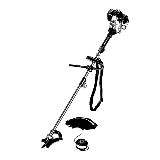
- Page 7 Spark Arrestor •=p---Spark Plug APPLICATIONS AS a trimmer: • CuRing gross and light weeds. • Edging. Muffler Guard --> • Decorative trimming around trees, fences, etc. AS a brushcu_er; Fuel Cap • Cutting weeds and light bush of up to 1/2 inch in Starter Rope diameter.
- Page 8 INSTALLING AND ADJUSTINGTHEJ-HANDLE While holding the unit in the operating position (Fig. 3), position the J-handle to the location Place the J-handle between the top and middle that provides you the best grip. clamp pieces (Fig. 1). Tighten the clamp screws evenly, until the J-handle is secure.
- Page 9 REMOVING AND INSTALLING CUTTING Output Shaft ATTACHMENT SHIELD Remove the cutting attachment shield when using the unit as a brushcutter. WARNING: The cutting attachment shield should NOT be installed when operating unit with a blade. Remove the cutting attachment shield before removing or OutputSh installing the blade.
- Page 10 Install the Cutting Blade Align the shaft bushing hole with the locking rod slot and insert the locking rod into the bushing hole WARNING: To avoid serious personal injury, (Fig. 8, Pg. 9). always wear gloves while handling or Put the blade retainer and nut on the output shaft. installing the blade.
- Page 11 3. While holding the locking rod, loosen the nut on Cutting Attachment the blade by turning it clockwise with a 5/8 inch closed-end or socket wrench (Fig. 14). Remove the nut, blade retainer, and blade. Store the nut and blade together for future use in a secure Blade Retainer place.
- Page 12 Pour the entire bottle of oil into the oil fill hole FUELING UNIT (Fig, 18), and its vapors can explode if ignited. To avoid serious personal injury, always stop the engine and allow it to cool before filling the fuel tank. Do not smoke while filling the tank. ARNING: Gasoline is extremely flammable Keep sparks and open flames away from the...
- Page 13 STARTING INSTRUCTIONS PulI the starter rope 1 to 3 pulis until the engine starts. Run for 15-30 seconds, if the unit fails to start Cold Start - First Start of the Day or Engine Ran Out return to step 7. of Fuel 10.
- Page 14 STOPPING INSTRUCTIONS 2. To stop the engine, put the Start!Stop Engine Control in the STOP [O] position (Fig. 20). Release your hand from the throttle control (Fig. 22). Allow the engine to idle. OPERATING THE EZ-LINK SYSTEM While firmly holding the add-on, push it straight into the EZ-Link coupler (Fig.
- Page 15 HOLDING THE TRIMMER Each time the head is bumped, about 1 inch (25.4 mm,) of trimming line is released. A blade in the cutting WARNING: Always wear eye, hearing, foot, attachment shield will cut the line to the proper length if body protection and strap to reduce the risk excess line is released.
- Page 16 DECORATIVE TRIMMING WARNING: The blade continues to spin after! Decorative trimming is accomplished by removing all the engine is turned off. The coasting blade can seriously cut you if accidentally touched. vegetation around trees, posts, fences, etc. Rotate the whole unit so that the cutting attachment is at •...
- Page 17 Check the indexing teeth on the inner reel and outer spool for wear (Fig. 33). If necessary, remove burrs or Always use geniune Troy-Bilt 0.105 in. (2.667 mm) replace the reel and spool. replacement line. Line other than specified may make the engine overheat or fail.
- Page 18 ForUsewithSingle ForUse withSplitLine Line ONLY or Single Line Slotted Holes Loop Fig. 37 Fig. 34 10. Before winding, split the line back about 6 inches. Single Line Installation 11. Wind the line in tight even layers in the direction Go To Step 8 for SplitLine Installation indicated on the inner reel.
- Page 19 INSTALLING A PREWOUND REEL Remove the oil fill plug/dipstick and check oil level, Oil should be up to the top of the dipstick (Fig. 40). 1. Hold the outer spool with one hand and unscrew the If the level is low, add a small amount of oil to the oil bump knob clockwise (Fig.
- Page 20 CHANGING THE OIL 4. Wipe up any oil residue on the unit and clean up any oil that may have spilled. Dispose of the oil For a new engine, change the oil after the first 10 hours according to Federal, State and local regulations. of operation.
- Page 21 AIR FILTER MAINTENANCE Cleaning the Air Filter WARNING: To avoid serious personal injury, t always turn your trimmer off and allow it to cool before you clean or do any maintenance on it, Clean and re-oil the air filter every 10 hours of operation, It is an important item to maintain, Not maintaining the air filter will VOID the warranty, 1.
- Page 22 CARBURETOR ADJUSTMENT Checking the fuel, cleaning the air filter, and adjusting the idle speed screw should solve most engine The idle speed of the engine is adjustable. An idle problems. adjustment screw is reached though a hole in the top of If not and: the engine cover (Fig 50).
- Page 23 Rocker Arms Remove the screw on back of the engine cover Nuts (Fig. 53). Feeler Gauge Gasket Fig. 53 Clean dirt from around the spark plug. Remove the Fig, 55 ..... spark plug from the cylinder head by turning a 5/8 in. socket counterclockwise.
- Page 24 REPLACING THE SPARK PLUG SPARK ARRESTOR MAINTENANCE Remove the muffler cover. See Rocker Arm Use only Champion RDZ19H spark plug or equivelent. The correct air gap is 0.025 in. (0.655 mm). Remove the plug Clearance, Pg. 22. after every 25 hours of operation and check its condition. 2.
- Page 25 CLEANING LONG TERM STORAGE If the unit wilBbe stored for an extended time, WARNING: To avoid serious personal injury, always turn your trimmer off and allow it to Drain all gasoline from the gas tank into a container. cool before you clean or do any maintenance Do not use gas that has been stored for more than on it.
- Page 26 CAUSE ACTION Ignition switchis Turn switch to ON Fill fueI tank Empty fuel tank Primer bulb wasn't pressed enough Press primer bulb fully and slowly 5-7 times Engine flooded Use starting procedure with choke lever in the RUN position, Pg+ 13 Old Gasoline Drain fuel tank/Add fresh Gasoline...
- Page 27 Engine Type ..............Air-Cooled, 4-Cycle Displacement ..............1.6 cu. in. (26.2 cc) Clutch Type ................. Centrifugal Operating RPM (Trimmer) ............7,200-8,300 Operating RPM (Brushcutter) ............7,200-9,800 Idle Speed RPM ..............3,000-3,600 Ignition Type ................. Electronic Ignition Switch ..............Rocker Switch Valve clearance (intake and exhaust) ........
- Page 28 ENGINE PARTS - MODEL TB490BC 4-CYCLE GAS TRIMMER (ppn - 41ADT49C063) (Serial Number 011 ..and greater) Part Numbers On Following Page Reissued12/01...
- Page 29 ENGINE PARTS - MODEL TB490BC 4-CYCLE GAS TRIMMER (ppn - 41ADT49C063) (Serial Number 011 ..and greater) Part_Lo_ IJ,_m _:t _L_. 79!-182338 Engine Cover 791-18t247 Painut 791-182339 Engine Cover Screws 753-1199 Recoil Pulley 791-!8!925 Valve Cover Screw 791-613102 Recoil Spring 791-!82098 Valve Cover 791-182366...
- Page 30 BOOM AND TRIMMER PARTS - MODEL TB490BC 4-CYCLE GAS TRIMMER ®( Descrij_tion 791-00040 Throttle Housing and Tdgger Assembly (includes 2-4) 791-00041 791-00042 Throttle Trigger Lock-Out Throttle Trigger 791-182690 Throttle Trigger Spring 791-182673 Switch Assembly 791-6!0327 Harness Clip 753-1247 Upper Drive Shaft Housing Assembly 79!-!81099 J-Handle Assembly (includes 9 &...
- Page 32 ° +glIIIIIIL _ ,llmllllV _mmm The limited warranty set forth below is given by Troy-Bilt entity, including a dealer or retailer, with respect to LLC with respect to new merchandise purchased and any product shall bind Troy-Bilt LLC During the period used in the United States, its possessions and territories.
Need help?
Do you have a question about the TB490BC and is the answer not in the manual?
Questions and answers