Table of Contents
Advertisement
Available languages
Available languages
Advertisement
Table of Contents

Related Manuals for Toro TimeCutter Z5030


Summary of Contents for Toro TimeCutter Z5030
- Page 1 Form No. 3360-826 Rev A Count on it. TimeCutter_ Z5030 and Z5060 Riding Mower Model No. 74373mSerial No. 290000001 and Up Model No. 74375mSerial No. 290000001 and Up G007648 Register at www.Toro.com. Original Instructions (EN)
- Page 2 Safety ................on the product. Write the numbers in the space Safe Operating Practices ........provided. Toro Riding Mower Safety ........Slope Chart ............Safety and Instructional Decals ......Product Overview ............Contact us at www.Toro.com. © 2008--The Toro®...
- Page 3 Controls ............. Safety Operation ..............Think Safety First ..........This machine meets or exceeds the B71.1-2003 Recommended Fuel ..........specifications of the American National Standards Checking the Engine Oil Level ......Institute, in effect at the time of production. Starting and Stopping the Engine ......However, improper use or maintenance...
- Page 4 Remove or mark obstacles such as rocks, tree limbs, A hitch kit is available for this machine and can be etc. from the mowing area. Tall grass can hide obtained by contacting an Authorized Toro Dealer. obstacles. Do not tow without first installing this manufacturer...
-
Page 5: Toro Riding Mower Safety
Always place containers The following list contains safety information specific to the ground away from your vehicle before filling. Toro products or other safety information that you must know that is not included in the ANSI standards. Remove gas-powered equipment from the truck or trailer and refuel it on the ground. - Page 6 Use only 7bro approved attachments. \K2arranty may be voided if used with unapproved attachments. If loading the machine onto a trailer or truck, use a single, full-width ramp onl> The ramp angle should not exceed i5 degrees. Note: Determine the left and right sides of the machine from the normal operating position.
- Page 7 No Slope FFFF FFFF FFFF Example: Compare slope with folded edge...
-
Page 8: Safety And Instructional Decals
Safety and Instructional Decals Safety decals and instructions are easily visible to the operator and are located near any area of potential danger. Replace any decal that is damaged or lost. 114-1606 Entanglement hazard, belt--keep all guards in place. 106-8717 Read the instructions before servicing or performing maintenance. - Page 9 N(Q) 112-9751 Parking position Neutral Fast Reverse Slow 112-9802 114-8531 Height-of-cut Bypass lever position for Bypass lever position for operating the machine pushing the machine 115-2501 114-8532 Fast Power take-off (PTO), Blade control switch on Bypass lever position for Bypass lever position for some models operating the machine pushing the machine...
- Page 10 115-2469 Warning--read the Operator's ManuaL Warning--read the instructions before servicing or performing maintenance; move the motion control levers to the park (brake) position, remove the ignition key and disconnect the spark plug wire. Cutting/dismemberment hazard, mower blade; entanglement hazard, belt--do not open or remove safety shields while engine is running.
-
Page 11: Product Overview
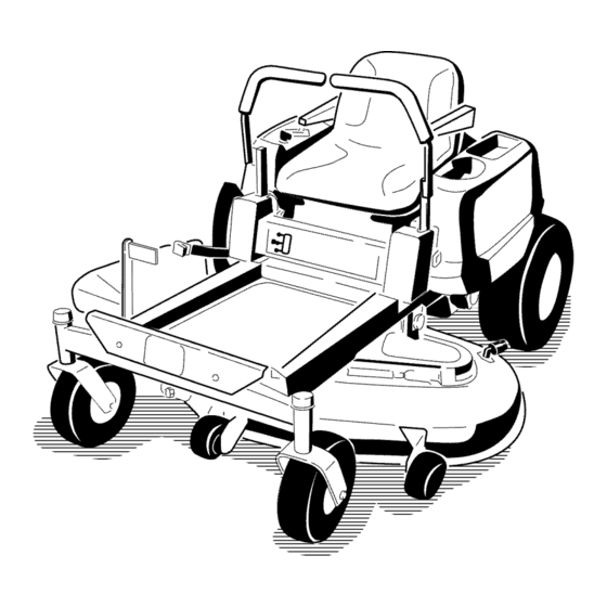
Product Overview G007649 Figure Rear drive wheel Footrest Control panel Anti-scalp roller Front caster wheel Height of cut lever Motion control levers Washout fitting Mower deck Fuel gauge Operator seat .3005369 Figure 4 Deflector Motion control levers Gas tank cap Foot assist pedal (Model 74375 only) Height of cut lever... -
Page 12: Controls
Controls reverse; wheel speed is proportional to the amount lever is moved. Move the control levers outward from Become familiar with all of the controls in Figure the center to the park position and exit the machine Figure 4, and Figure 5 before you start the engine and (Figure... -
Page 13: Operation
Operation Note: Determine the leKt and right sides of the machine from the normal operating position. Think Safety First Please carefully read all of the safety instructions decals in the safety section. Knowing this information could help you, your famil 5 pets or bystanders avoid injur>... - Page 14 In certain conditions, gasoline is extremely In certain conditions during fueling, static flammable and highly explosive. A fire or electricity be released causing a spark explosion from gasoline can burn which can ignite the gasoline vapors. A fire others and can damage property.
-
Page 15: Checking The Engine Oil Level
tank (Figure 9). This space in the neck of the tank Add the correct amount of gas stabilizer/conditioner allows gasoline to expand. Do not fill the fuel tank to the gas. completely full. Note: A fuel stabilizer/conditioner is most effective Install the fuel tank cap securely. -
Page 16: Operating The Blades
between attempts. Failure to follow these instructions can damage the starter motor. G005056 Figure 10 Blade control switch--Off Control panel position G005058 Move the throttle lever to Choke before starting a cold engine (Figure 1 i). Figure 12 Control panel Note: A warm or hot engine may not require... -
Page 17: Stopping The Engine
The Safety Interlock System If safety interlock switches are disconnected or damaged the machine could operate unexpectedly causing personal injury. • Do not tamper with the interlock switches. G005059 • Check the operation of the interlock switches daily and replace any damaged switches before... -
Page 18: Driving Forward Or Backward
Driving Forward or Backward The throttle control regulates the engine speed measured in rpm (revolutions per minute). Place the throttle control in the Fast position for best performance. Always operate in the full throttle position. machine spin very rapidly. operator lose control of the machine... -
Page 19: Stopping The Machine
Adjusting the Height of Cut To turn,release the pressure on the motion control lever toward the direction you want to turn. Using the Height of Cut Lever To stop, push the motion control levers to neutral. To adjust the height of cut, pull inward and up on the Stopping the Machine... -
Page 20: Positioning The Seat
Using the Foot Assist Pedal (Model Positioning the Seat 74375 only) The seat can move forward and backward. Position The foot assist pedal can be used with the height of cut seat where you have the best control of the machine and are most comfortable. - Page 21 Move the bypass levers rearward and then down to lock them in place as shown in Figure 22 to disengage the wheel motors. Repeat this on each side of the machine. Move the motion control levers inward to the neutral position.
- Page 22 Mowing Direction Alternate mowing direction to keep the grass standing Without the grass deflector, discharge cover, straight. This also helps disperse clippings which or complete grass catcher assembly mounted enhances decomposition and fertilization. in place, and others are exposed to blade contact and thrown debris.
- Page 23 W wear or damage. File down aW nicks and sharpen the blades as necessar> a blade is damaged or worn, replace it immediately with a genuine Toro replacement blade.
-
Page 24: Maintenance
Maintenance Note: Determine the left and right sides of the machine from the normal operating position. Recommended Maintenance Schedule(s) Maintenance Service Maintenance Procedure Interval • Check the safety interlock system. • Check the air cleaner for dirty, loose or damaged parts. •... -
Page 25: Premaintenance Procedures
Lubrication Premaintenance Procedures Greasing the Bearings Raising the Seat Service Interval: Ever3:25 hours--Grease lubrication points. Make sure the motion control levers are locked in the Grease Type: No. 2 General Purpose Lithium Base park position. Lift the seat forward. Grease The following components can be accessed... -
Page 26: Servicing The Air Cleaner
Engine Maintenance Connect a grease gun to each fitting (Figure 24 and Figure 25). Pump grease into the fittings until grease begins to ooze out of the bearings. Servicing the Air Cleaner 5. Wipe up any excess grease. Service Interval: Before each use or daily--Check air cleaner... -
Page 27: Servicing The Engine Oil
Servicing Paper Element Checking the Oil Level Service Interval: Every 50 hours--Service the paper Service Interval: Before each use or daily--Check element. (more often under extremely engine oil level. dust3; dirty conditions) Park the machine on a level surface, disengage Every i00 hours--Replace the paper blade control... - Page 28 low,addoil oKthepropertypeup to the Kull m ark. Reinstall o il fill cap/dipstickandscrewtight. Changing the Oil and the Filter Service Interval: Every I00 hours--Change the engine oil and filter. Refill with service class SG, SH, SJ or higher oil as specified in the "Viscosity Grades" table. Change the oil and filter while the engine is still warm.
-
Page 29: Servicing The Spark Plug
12.Installthe replacement oil filter to the adapter. Turn theoil filter clockwise until therubbergasket contacts the pad, additional then tighten filter an 3/4 to i turn (Figure 30). Wipe up aW excess oil on the frame. 13. When oil has drained completely, install the oil drain plug. -
Page 30: Cleaning The Blower Housing
Cleaning the Blower Housing Fuel System Maintenance To ensure proper cooling, make sure the grass screen, cooling fins, and other external surfaces of the engine are kept clean at all rimes. Annually or every 100 hours of operation (more often under extremely dust 5 dirty conditions),... - Page 31 Electrical System Maintenance Charging the Battery CALIFORNIA Proposition 65 Warning Battery posts, terminals, related accessories contain lead and lead compounds, G00507I chemicals known to the State of California to cause cancer reproductive harm. Wash hands after handling. Figure Fuel line from tank Fuel line to engine Removing the Battery...
- Page 32 Incorrect battery cable routing could damage the machine and cablescausingsparks. Sparks can causethe battery gassesto explode, resulting in personalinjury. • Mways disconnect the negative (black) battery cable before disconnecting positive (red) cable. G000538 Figure 35 • Mways connect the positive (red) battery cable...
-
Page 33: Drive System Maintenance
Drive System Maintenance Checking the Tire Pressure Service Interval: Every 25 hours--Check tire pressure. G005073 Maintain the air pressure in the front and rear tires as specified. Uneven tire pressure can cause uneven cut. Check the pressure at the vane stem (Figure 37). -
Page 34: Mower Maintenance
Pile down any nicks and sharpen blades as necessary. If a blade is damaged or worn, replace it immediately with a genuine Toro replacement Checking for Bent Blades blade. For convenient sharpening and replacement, may want to keep extra blades on hand. - Page 35 1/8 inch (3ram), the blade spindle could be bent. Contact an Authorized Toro Dealer for service. Measure from the tip of the blade to the fiat surface If the variance is within constraints, move to the here. The variance...
-
Page 36: Leveling The Mower Deck
Leveling the Mower Deck Check to ensure the mower deck is level any time you install the mower or when you see an uneven cut on your lawn. The mower deck must be checked for bent blades prior to leveling; any bent blades must be removed and replaced. - Page 37 G005278 Figure 47 Mower Decks with 3 Blades Blades side to side Outside cutting edges Sail area of blade Measure from the tip of the blade to the flat surface here G005074 Measure between the outside cutting edges the flat surface (Figure 46 and Figure 47).
-
Page 38: Removing The Mower
Figure 49 Mower Decks with 2 Blades Blades front to rear Measure from the tip of the blade to the flat surface here G005075 Figure 51 Lock nut 1. Adjusting rod Adjusting block To raise the front of the mower, tighten adjustment nut. -
Page 39: Mower Belt Maintenance
Mower Belt Maintenance Inspecting the Belts Service Interval: Every 25 hours--Check the belts for wear/cracks. Check the belts for cracks, frayed edges, burn marks, or any other damage. Replace damaged belts. Replacing the Mower Belt Squealing when the belt is rotating, blades slipping when G005076 cutting... -
Page 40: Replacing The Grass Deflector
Route the new belt around the engine pulley and mower pulleys (Figure 54). Pull the idler pulley in the direction shown Figure 54 and route the belt onto the idler pulley (Figure 54). 8. Install the belt covers over the outside spindles. -
Page 41: Cleaning
Note: Cleaning If the mower is not clean after one washing, soak it and let it stand for 30 minutes. Then repeat the process. Washing the Underside of the Run the mower again for one to three minutes Mower remove excess water. -
Page 42: Engine Maintenance
Storage Important: Do not store stabilizer 1conditioned gasoline over 30 days. Cleaning and Storage Remove the spark plug(s) and check condition; refer to Servicing the Spark Plug in the Engine 1. Disengage the blade control switch, move the Maintenance section. With the spark plug(s) motion... - Page 43 Troubleshootin Problem Possible Cause Corrective Action The engine overheats. 1. The engine load is excessive. 1. Reduce ground speed. 2. The oil level in the crankcase is low. 2. Add oil to the crankcase. 3. Remove the obstruction from the 3.
- Page 44 Problem Possible Cause Corrective Action There is abnormal vibration. 1. The engine mounting bolts are loose. 1. Tighten the engine mounting bolts. 2. The engine pulley, idler pulley, or blade 2. Tighten the appropriate pulley. pulley is loose. 3. Contact an Authorized Service Dealer. 3.
- Page 45 KEY SWITCH CONNECTIONS KEY SWITCH LEGEND = NO CONNECTION = BIAANDXY START =BIS l-l= VIEWED FROM BACK OF SWITCH PK _ ENGINE CONNECTIONS IGNITION (OPERATOR (SHOWN OFF') IN SEAT) MODULE _.=.oUT i \ _-_/ RH NEUT SWITCH (IN NEUT , II LOCK) I i _SOLENOID 1_"...
- Page 46 Notes:...
- Page 47 Notes:...
- Page 48 Countries Other than the United States or Canada Customers who have purchased Toro products exported from the United States or Canada should contact their Toro Distributor (Dealer) to obtain guarantee policies for your country, province, or state. If for any reason you are dissatisfied...
- Page 49 N° de modelo 74375mN ° de serie 290000001 y superiores mmmm G007648 Para registrar su producto o para descargar un Manual del operador o un Catalogo de piezas sin cargo alguno, vaya Traducci6n del original (ES) a www.Toro.com.
-
Page 50: Lyndale Avenue South Bloomington, Mn
Servicio Tdcnico Autorizado o con Asistencia al Cliente Toro, y tenga a mano los nt_meros de modelo y serie de su producto. Figura 1 identifica la ubicaci6n de los © 2008--The Toro® Company Pongase en contacto con nosotros en www.Toro.com. -
Page 51: Table Of Contents
....................Seguridad Limpieza ..............Prficticas de operaci6n segura ........ C6mo lavar los bajos del cortac&ped ....Seguridad para cortac&pedes Toro Almacenamiento ............conductor ............Limpieza y almacenamiento ........ Diagrama de pendientes ........Soluci6n de problemas .......... -
Page 52: B71.I
Seguridad No utilice la m(tquina sin tenet colocado funcionando un deflector, una tapa de descarga o el sistema de recogida de hierba completo. Esta mfiquina cumple o supera las especificaciones de la norma ANSI B71.1-2003 vigentes en el Est_ alerta, vaya m(ts despacio y extreme momento de la fabricaci6n. - Page 53 Distribuidor hacer que patinen las ruedas motrices, causando autorizado Toro. No remolque sin haber instalado este p&dida de frenado o de direcci6n. enganche homologado. Las siguientes directrices aplicables cuando...
-
Page 54: De Seguridad
Seguridad para cortacdspedes en todo momento basra que termine de repostar. Toro con conductor urilice dispositivos que mantengan abierta la boquilla. Si se derrama combustible sobre su ropa, cfimbiese La siguiente lista contiene informaci6n especifica para de ropa inmediatamente. - Page 55 No Slope FFFF FFFF FFFF Example: Compare slope with folded edge dk=t "0...
- Page 56 Pegatinas de seguridad e instrucciones Las pegatinas de seguridad e instrucciones estfin a la vista del operador y estfin ubicadas cerca de cualquier zona de peligro potencial. Sustituya cualquier pegatina que est8 dafiada o que falte. 114-1606 Peligro de enredamiento, correa - mantenga cotocados 106-8717 todos los protectores.
- Page 57 N(¢) 112-9751 Punto muerto Posici6n de aparcado Marcha atr_s R&pido Lento 112-9802 114-8531 Altura de corte Posici6n de ta patanca de Posici6n de la palanca desvio para empujar la de desvio para operar la m_quina m_quina 115-2501 Toma de fuerza (PTO), R_pido 114-8532 Mando de control de...
- Page 58 ®A Simbolos de la bateria Algunos de estos simbolos, o todos ellos, estan en su bateria Riesgo de explosi6n Mantenga a otras personas a una distancia prudencial de la bateria. No fume, mantenga Lleve protecci6n ocular; atejado det fuego y de las los gases exptosivos llamas desnudas.
- Page 59 117-1224 Indicador de combustible Lleno Medio Ileno Vacio 117-1268 Indicador de combustible Lleno Medio Ileno Vacio...
- Page 60 El producto G007649 Figura Panel de control Rueda motriz trasera Reposapi6s Rodilto protector det c6sped Palancas de control de Conector de lavado Patanca de ajuste de altura Rueda giratoria delantera de corte movimiento Indicador de combustible Plataforma de corte Asiento det operador .3005369 Figura 4 Palancas de control de...
- Page 61 Controles Palancas de control de movimiento posicion de aparcado Antes de poner en marcha el motor y trabajar con la m_iquina, familiadcese con todos los controles: Figura 3, Las palancas de control de movimiento son controles sensibles a la velocidad que controlan motores de rueda...
- Page 62 raclon "" Nota: Los lados dereeho e izquierdo de la m£quina dctcrminan dcsdc la posici6n normal del opcrador. Primero la seguridad Le rogamos lea cuidadosamente todas las instrucciones y pegatinas de la secci6n de seguridad. Esta informaci6n puede aFudarle a evitar lesiones al operador, a su familia, a sus animales...
- Page 63 En determinadas condiciones durante En ciertas condiciones la gasolina extremadamente inflamable y altamente repostaje, puede tener lugar una descarga explosiva. Un incendio o una explosi6n electricidad estfitica, produciendo chispa provocados por la gasolina puede causarle que puede prender los vapores de la gasolina.
- Page 64 Como Ilenar el deposito • Mantiene la gasolina fresca durante un pedodo combustible de almacenamiento de 30 dias o menos. Para un almacenamiento m(ts largo, se recomienda drenar Pare el motor y ponga los controles de movimiento dep6sito de combustible. en la posici6n de aparcar.
- Page 65 Importante: active el motor de arranque Desengrane las cuchillas moviendo el mando control de las cuchillas a Desengranado (Figura 10). durante mils de 10 segundos cada vez. Si el motor no arranca, deje que se enfrie durante 60 segundos entre intentos.
- Page 66 El sistema de interruptores de 1. Deje depresionar l aspalancas d e controlde movimientoy pongala mfiquina enpuntomuerto. seguridad 2. Muevael acelerador a laposici6nRfipido. 3. Tire hacia arriba del mando de control las cuchillas para desplazarlo a la posici6n Engranado y engranar las cuchillas (Figura 13).
- Page 67 SKntese en el asiento, mueva el mando de control de las cuchillas a desengranado y bloquee palancas de control de movimiento en la posici6n de aparcar. Arranque el motor. Con el motor en marcha, engrane el mando de control de las cuchillas y lev(mtese un poco...
- Page 68 Para ir recto, aplique la misma presi6n a ambas palancas de control de movimiento (Figura 17). Para girar, deje de empujar la palanca de control movimiento del lado al que desea girar. Para detenerse, empuje las palancas de control de movimiento a la posici6n de punto muerto.
- Page 69 G009619 Figura 18 Palanca de ajuste de la 76 mm (3 pulg.) altura de corte 115 mm (4,5 pulg.), 64 mm (2,5 pulg.) Posici6n de transporte 102 mm (4 pulg.) 51 mm (2 pulg.) 89 mm (3,5 pulg.) 38 mm (1,5 pulg.) Uso del pedal de elevacion asistida (Modelo...
-
Page 70: A Mano
Figura 20 Pomo de ajuste 2. Ponga el asiento en la posici6n deseada y apriete G005062 el pomo. Figura Brazo de la patanca de Taladro superior alargado control Ajuste de las palancas de Palanca de control Pemo control de movimiento Repita el ajuste con la otra palanca de control. - Page 71 3. Localice las palancas de desvio en la parte trasera de la mfiquina, en los lados izquierdo y derecho basridor. Sin el deflector de hierba, la tapa de descarga o el recogedor completo adecuadamente Mueva las palancas de desvio hacia atrfis y luego °...
- Page 72 Si una cuchilla estft desgastada o deteriorada, sustitfyala que avanza el verano, la velocidad de crecimiento inmediatamente por una cuchilla nueva genuina Toro. la hierba decrece, por ello debe cortarse con menor frecuencia. Si no puede cortar la hierba durante perfodo...
-
Page 73: De Mantenimiento
Mantenimiento Nota: Los lados derecho e izquierdo de la m_quina se determinan desde la posici6n normal del operador. Calendario recomendado de mantenimiento Intervalo de manteni- Procedimiento de mantenimiento miento y servicio • Compruebe el sistema de interruptores de seguridad. • Compruebe que el limpiador de aire no tiene piezas sucios, sueltos o dafiados. °... -
Page 74: Al Mantenimiento
Lubricacidn Procedimientos previos al mantenimiento Engrasado de los cojinetes Intervalo de mantenimiento: Cada Cbmo levantar el asiento horas--Lubrique todos los puntos engrase. AsegtSrese de que las palancas de control de movimiento estfin bloqueadas en la posici6n de aparcar. Mueva Tipo de grasa: Grasa de lirio de prop6sito general N °... -
Page 75: Del Motor
Mantenimiento del motor Mantenimiento del limpiador de aire Intervalo de mantenimiento: Cada vez que se urilice o diariamente--Compruebe que el limpiador de aire no tiene piezas sucios, sueltos o dahados. Este motor est(t equipado con un elemento limpiador aire de papel recambiable de alta densidad. - Page 76 nuevo; no lo use si las superficies sellantes est(m dobladas o dafiadas. Compruebe la base del limpiador de aire segfin sea necesario y verifique la condici(Sn. Coloque el element() de papel sobre la base del limpiador de aire. Cierre el enganche. Cierre la puerta de la tapa del limpiador de aire.
- Page 77 impurezas. A segdrese d e queel motor est_nivelado Asegdrese de que dejar tiempo suficiente para que el antesdereponer, e omprobar o eambiar e l aeeite. aceite se drene completamente. 10. Localice el film) de aceite situado en el lado derecho Cambieel aceite y el _ltro deaeeite segdn seindicaa eondnuaei6n: del motor.
- Page 78 motor est(t funcionando correctamente. Si el aislante Mantenimiento de la bujia aparece de color negro, significa que el limpiador Intervalo de mantenimiento: Cada aire est(t sucio. horas--Compruebe el estado Importante: No limpie nunca la bujia. Cambie la(s) bujfa(s) y el espacio entre los electrodos.
- Page 79 Mantenimiento sistema de combustible ciertas condiciones la gasolina extremadamente inflamable y altamente explosiva. Un incendio o una explosi6n provocados por la gasolina puede causarle quemaduras a usted y a otras personas asi como dafios materiales. G005071 Realice cualquier tipo de mantenimiento relacionado con el sistema de combustible...
- Page 80 Mantenimiento sistema el ctrico Un enrutado incorrecto de los cables de la bateria podria dafiar la mfiquina y los cables, causando chispas. Las chispas podrian hacer Cbmo cargar la bateria explotar los gases de la bateria, causando lesiones personales. • Desconecte siempre el cable...
-
Page 81: De Los Fusibles
FI - 30 amperios, Cargue la bateda a un ritmo de 6 a 10 amperios • Principal tipo chapa durante 1 hora como mfnimo. No sobrecargue • Circuito de carga F2 - 25 amperios, tipo chapa bateda. 1. Levante el asiento para tenet acceso al portafusibles Cuando... - Page 82 Neumfiticos traseros: 90 kPa (13 psi) sustit6yala inmediatamente pot una cuchilla nueva genuina Toro. Para que el afilado y la sustituci6n sean Neumfiticos delanteros (ruedas giratorias): 24i kPa mils c6modos, puede desear tenet un stock de cuchillas (35 psi) de repuesto.
- Page 83 Inspeccione los filos dc cortc (Figura 38). Si los Mida aqu_ la distancia entre la punta de la cuchilla bordcs no esdm afilados o tienen mellas, retire las la superficie plana. cuchillas y af{lelas; consulte C6mo afilar las cuchillas. Inspeccione las cuchillas, cspecialmente la parte...
- Page 84 (Figura 45). Si la su Distribuidor autorizado Toro para que revise cuchilla se mandene horizontal, esg equilibrada y la m(tquina. puede utilizarse. Si la cuchilla no ester equilibrada, rebaje algo el metal en la parte de la vela solamente Si la difcrencia esg dentro de los lfmites, pase (Figura 44).
- Page 85 Importante: La parte curva de la cuchilla debe apuntar hacia arriba, hacia el interior cortac_sped para asegurar un corte correcto. G009682 Instale el refuerzo de la cuchilla, la arandela curva (con la copa hacia la cuchilla) y el perno de la cuchilla (Figura 43).
-
Page 86: De Las Cuchillas De Corte
Mueva las palancas de control de movimiento hacia exc_ntrica (Figura 48). Utilice una llave de extensi(m fuera a la posici6n de aparcar, pare el motor, retire de 3/8 pulgada de una llave de tubo para manipular la llave y espere a que se detengan todas las piezas placa exc_ntrica. - Page 87 Para ajustar la inclinaci(Sn longitudinal, gire la tuerca Retire el pasador y la chaveta de la varilla de soporte de ajuste de la parte delantera del cortacdsped delantera (Figura 52). Baje cuidadosamente la parte (Figura 5i). delantera de la plataforma del cortacdsped al suelo.
- Page 88 Deslice la plataforma del cortac6sped hacia atr_ts para retirar la correa del cortac6sped de la polea del motor. Retire la plataforma del cortac6sped de debajo de ° la m_quina. Nota: Guarde todas las piezas para instalaciones futuras. Mantenimiento de la correa del cortac sped tG005191 Figura 54...
- Page 89 que el deflector de hierba no est(t soporte del deflector de hierba y pot la arandela deteriorado. freno interna (Figura 55). Introduzca la varilla, en la parte delantera del ° deflector de hierba, pot el espaciador corto de la plataforma. Fije el extremo trasero de la varilla en el Si el hueco de descarga...
- Page 90 Limpieza Cierre el grifo de agua y retire el acoplamiento ° conector de lavado. Nota: Si el cortac&ped no queda limpio despu& de Cbmo lavar los bajos del un lavado, m6jelo bien y espere unos 30 minutos. cortacdsped Luego repita el proceso. Intervalo de mantenimiento: Cada vez que se utilice...
- Page 91 Almacenamiento Pare el motor, deje que se enfr_e, y drene el dep6sito de combustible; consulte Drenaje del dep6sito de combustible, en la secci6n Mantenimiento Limpieza y almacenamiento sistema de combustible. 1. Desengrane el mando de control de las cuchillas, Vuelva a arrancar el motor y h(tgalo funcionar hasta mueva los controles de movimiento hacia fuera a la...
- Page 92 Solucion de problemas Problema Posible causa Accion correctora El motor se sobrecalienta. Reduzca la vetocidad sobre el terreno. La carga del motor es excesiva. Arhada aceite at c_rter. El nivet de aceite det c_rter est_ bajo. Elimine la obstrucci6n de las atetas Las atetas de refrigeraci6n y los conductos de aire situados debajo del...
- Page 93 Problema Posible causa Accion correctora Las v_lvulas de desvio est_n abiertas. Cierre las v_tvulas de remotcado. No es posibte conducir la m_quina. 2. Las correas de tracci6n est_n P6ngase en contacto con et Servicio T6cnico Autorizado. desgastadas, suettas o rotas. 3.
- Page 94 KEY SWITCH CONNECTIONS KEY SWITCH LEGEND ¢D = NO CONNECTION = BIAANDXY START =BIS V1EWED FROM BACKOF SWITCH PK _ ENGINE CONNECTIONS (OPERATOR ,_N,T,ON (SHOWN OFF) IN SEAT) _,,o.o,,r , \ _-_ ) RH NEUT SWITCH r--_r--__ (IN NEUT FUEL SOL I II_FuEL LOCK) ' ' _SOLENOID...
- Page 95 Notas:...
- Page 96 Si por cualquier raz6n usted no esta satisfecho con el servicio ofrecido por su distribuidor, o si tiene dificultad en obtener informaci6n sobre la garantia, p6ngase en contacto con el importador Toro. Si fallan todos los demas recursos, puede ponerse en contacto con nosotros en Toro Warranty Company.
Need help?
Do you have a question about the TimeCutter Z5030 and is the answer not in the manual?
Questions and answers