Table of Contents
Advertisement
Quick Links
Download this manual
See also:
Operator's Manual
OWNER'S
GUIDE
Model Series
370 - 389
Rotary Mowers
IMPORTANT:
READ SAFETY RULES AND INSTRUCTIONS CAREFULLY
Warning:
This und is equipped with an internal combustionengine and should not be used on or near any unimproved forest-
covered, brush-covered or grass-covered land unless the engine's exhaust system is equipped with a spark attester meeting
applicable local cr state laws (it any). If a spark arrester is used, it should be maintained in effective workingorder by the operator.
In the State of California the above is required by law (Section 4442 of the California Public Resources Code). Other states may have
similar laws. Federal laws apply on federal lands. A spark arrester for the muffler is available through your nearest engine authorized
service dealer or contact the service department, P.O. Box 368022 Cleveland, Ohio 44136-9722.
MTD PRODUCTS
INC. P.O. BOX 368022 CLEVELAND,
OHIO 44136-9722
PRINTED IN U.S.A.
FORM NO. 770-0420M
Advertisement
Table of Contents

Related Manuals for Yard Machines 370 Series


Summary of Contents for Yard Machines 370 Series
- Page 1 OWNER'S GUIDE Model Series 370 - 389 Rotary Mowers IMPORTANT: READ SAFETY RULES AND INSTRUCTIONS CAREFULLY Warning: This und is equipped with an internal combustionengine and should not be used on or near any unimproved forest- covered, brush-covered or grass-covered land unless the engine's exhaust system is equipped with a spark attester meeting applicable local cr state laws (it any).
-
Page 2: Important Safe Operation Practices
SECTION 1: IMPORTANT SAF E OPERATION PRACTICES WARNING: THIS SYMBOL POINTS OUT IMPORTANT SAFETY INSTRUCTIONS WHICH, IF NOT FOLLOWED, COULD ENDANGEr THE PERSONAL SAFETY AND/OR PROPERTY OF YOURSELF OTHERS. READ FOLLOW INSTRUCTIONS THIS MANUAL BEFORE ATTEMPTING TO OPERATE Y3UR LAWN MOWER. -
Page 3: Slope Operation
• Do not mow slopes greater than 15 degrees as , Never operate the mower in wet grass. Always be shown on the slope gauge. sure of your footing. A slip and fall can cause serious personal injury. Keep a firm hold on the handle and •... -
Page 4: Section 2: Finding Your Model Number
worn). Replace with blade which meet.' original Grass catcher components subject to wear, equipment specifications listed in this manuEL damage deterioration, which could expose moving parts or allow objects to be thrown. • Keep all nuts, bolts, and screws tight to be sure the safety protection, frequently check components... -
Page 5: Unpacking Instructions
SECTION 3: CALLING CUSTOMER SUPPORT If you are having difficulty assembling this product or if you have any question regarding the controls, operation or maintenance of this mower, please call the Customer Support Department. You can reach them by calling: 1-800-800-7310 Before you call, make sure that you have bolh your model and serial number ready. -
Page 6: Items Required
SECTION 5: SET-UP INSTRUCI"IONS This guide covers models 370 - 379 single speed self propelled mowers and 380 - 389 six speed self propelled mowers. Much of this guide pertains to both models. However, there are some areas where only one, model is covered. Use only the information that is appropriate... - Page 7 Step 4. Raise complete handle assembly until it Step 3, Tighten wing nuts. clicks into place. Make sure not to kink the control cables. Handle Assembly HERE Pinch lower handle against mounting Step 7. Attach control cables to handle with pull Step 5.
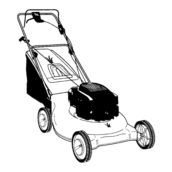
- Page 8 SECTION 6: CONTROLS Control Handle Recoil Starter Drive Clutch Control 'ottle Control g Height Adjustment Lever All Models Models 380 - 389 Figure 5 BLADE CONTROLHANDLE The blade control handle is located on the ul)per handle of the mower. See Figure 5. The blade control handle must be depressed in order to start and operete the unit.
-
Page 9: Operation
NOTE: Only move the shift lever when the engine is running. Changing the shift lever setting with the engine off can cause damage to the mower. CUTTING HEIGHT ADJUSTMENT LEVER The cutting height adjustment lever is located above the left rear wheel. To adjust the cutting height, pull the lever out and away from the mower and then move it forward or back for a new cutting height. - Page 10 EACH TIME BEFORE YOU START YOIIR MOWER • Attach spark plug wire to spark plug. I_lake certain the metal cap on the end of lhe spark plug wire is fastened securely over the metal tip on tt _espark plug. • Check for proper drive clutch operation using the NEUTRAL ADJUSTMENT TEST.
- Page 11 BAGGING GRASS CLIPPINGS This mower can bag grass clippings. Follow steps 1 and 2 to ready the mower for bagging, Step 1. Remove mulching plug, if installed. Step 2. Hang grass bag on mower. HERE EMPTYING A FULL BAG OF GRASS Once the grass bag is full it will need to be emptied, follow steps 3 and 4 to empty the grass bag.
-
Page 12: Height Adjustment
MULCHING GRASS CLIPPINGS This mower can also mulch grass clippings. F(,llow step 1 to ready this mower for mulching. S_pl. Lilt rear flap, remove grass bag, if Mulching plug top and bottom view. installed, and insert mulching plug. This side up This side down SECTION 8: ADJUSTMENTS... -
Page 13: Throttle Control Adjustment
• Place the hairpin clips in the inner holes in the weld pins and attach the starter rope as instructed in the Set- Up Instructions. THROTTLE CONTROL ADJUSTMENT Lever Clamp On Engine I Figure 8 If the throttle control requires adjustment or if it has been replaced, adjust the throttle control as follows. •... -
Page 14: Section 10: Maintenance
SECTION 9: LUBRICATION any kind of work on the lawn mower. WARNING: Always stop engine aid disconnect spark plug wire before cleaning, lubricating or doing Elade Control LUBRICATE. Wheels Engine SEE ENGINE MANUAL Figure 10 Blade Control: Lubricate the pivot points on the blade control handle and the brake cable at least once a season with light oil. - Page 15 • Cleanthe engineregularly w itha cloth or brush, Keep the cooling syslem (blower housing area) clean to permit proper air circulation which is essential to engine performance and life. Be certain to remove all grass, dirt and combustible debris from muffler area, DECK The underside of the mower deck should be cleaned after each use to prevent a buildup of grass clippings, leaves, dirt or other matter.
- Page 16 TROUBLE SHOOTING Refer to the trouble shooting section of this mEnual for helpful inlormation. SHIFT LEVER CABLE ADJUSTMEN'I" (Models 380 - 389 Only) Periodic adjustment of the six speed shift cable may be required due to normal wear on the cable. Adjustment is needed if all six speeds do not work.
- Page 17 DRIVE BELT REMOVAL REPLACEMENT If you need to replace a worn or broken drive belt, follow steps t through 22. Step 1. Disconnect the spark plug and ground it. Drain the fuel tank. Step 2. Step 3, Remove rear hub caps and wheels. Step 4.
-
Page 18: Section 11: Off-Season
Step 14. Replace large baffle. Step 17. Replace the eight phillips head screws that hold the large baffle in place. Step 15. Replace small baffle and three h,._xhead screws holding it in place. Step 18. Replace the rear wheels, rear wheel gears and hub caps. -
Page 19: Shooting Guide
SECTION 12: TROUBLE SHOOTING GUIDE [Trouble Possible Cause(s) Corrective Action Blade control handle disengaged. Engine fails to start Engage _1 handle. Spark plug wire disconnected. Connect wire to spark plug. Throttle control lever net in correct Move throttle lever to FAST or START posi- starting position. - Page 20 SECTION 13: Assorted Parts List Models Models Description 380-389 370-379 190-119-000 190-119-000 Grass Bag Kit 731-1236 731-1236 Trailing Shield 732-0700 i732-0700 Trailing Shield Wi re Wheels 634-0020 734-1790 (Front) 734-1791 (Rear) Hub Caps 720-0249 731-1426 Blade 742-0741 (Mulch) 742-0741 (Mulch) 742-0641 (Std.) 742-0641 (Std.) 731-1685...
Need help?
Do you have a question about the 370 Series and is the answer not in the manual?
Questions and answers