Advertisement
Available languages
Available languages
Quick Links
Use & Care Guide
®
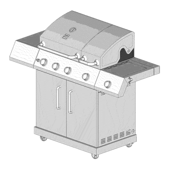
Liquid PropaneGas Grill
Sears Model No. 148.16656010
This Grill is for OutdoorUse Only
•
Read and follow all Safety, Assembly,
and Use & Care Instructions in this Guide
before assembling and cooking
with this grill.
•
Failure to follow all instructions in this
Use & Care Guide may leadto fire or
explosion, which could result in property
damage, personal injury or death.
•
Safety
•
Parts
•
Useand Care
•
Assembly
Grill InformationCenter
Missing Parts? Assembly Questions?
Operation Problems? Before returning
grill to store, call 1-800-482-0131
Tools needed for assembly:
Screwdriver ( notprovided)
SAVETHESEINSTRUCTIONS!
See our extensive assortmentof outdoor living productson-line at
www.sears.comand www.kmart.com
Sears Brands ManagementCorporation,Hoffman Estates,IL 60179, U.S.A.
© 2010Sears Brands,LLC
Printedin China
L3018S-ManuaE
Advertisement

Related Manuals for Kenmore 148.16656010

Summary of Contents for Kenmore 148.16656010
- Page 1 Use & Care Guide ® Liquid PropaneGas Grill Sears Model No. 148.16656010 This Grill is for OutdoorUse Only • Safety • Parts • Useand Care • Read and follow all Safety, Assembly, and Use & Care Instructions in this Guide •...
- Page 2 CALIFORNIA PROPOSITION 65 If you smell gas: 1. Combustion by-products produced when using this product contain chemicals known to the State 1. Shut off gas to the appliance. of California to cause cancer, birth defects, and 2. Extinguishany open flame. other reproductive harm.
- Page 3 Congratulations on making a smart purchase. Your new of normal use, accident or improper maintenance. Kenmore ®productis designed and manufactured for years of dependable operation. But like all products, it may require All warranty coverage is void if this grill is ever used for repair from time to time.
- Page 4 LP Cylinder • The LP cylinder used with your grill must meet the following requirements: • Use LP cylinders only with these required measurements: 12" (30.5cm) (diameter) x 18" (45.7 cm) (tall) with 20 lb. (9 kg.) capacity maximum. • NEVER store a spare LP cylinder under or near •...
- Page 5 LP Tank Exchange Connecting Regulator To The LP Tank •Many retailers that sell grills offer you the option of replacing 1. LP tank must be properly secured onto grill. (Refer to your empty LP tank through an exchange service. Use only assembly section.) those reputable exchange companies that inspect, precision 2.
- Page 6 Leak Testing Valves, Hose and Regulator 1.Turnall grillcontrolknobsto OFF. 2. Be sure regulator is tightly connected to LP tank. Completely open LP tank valve by turning OPD hand wheel counterclockwise. If you hear a rushing sound, turn gas off Holdcouplingnut and regulator immediately.
- Page 7 Safety Tips • Before opening LP cylinder valve, check the coupling nut for tightness. • When grill is not in use, turn off all control knobs and LP For Safe Use of Your Grill and to Avoid Serious cylinder valve. Injury: •...
- Page 8 5.Ifignition d oes not o ccur i n5seconds, turn theburner control off,wait 5 minutes forgastoclear a way, andrepeat thelighting p rocedure. 6.Tolight o ther b urners, repeat step 4. NOTE: Ifignitor does not w ork, follow Match Lighting instructions. Turn controls and gas source or tank OFF when Burner Flame Check not in use.
- Page 9 Donotusecitrisot, abrasive cleaners, degreasers Storing Your Grill concentrated grill c leaner onplastic p arts. Damage toand •Clean cooking grates. failure o fparts canresult. •Store in dry location. •Porcelain s urfaces: Because ofglass-like composition, most •When LP cylinder is connected to grill, store outdoors in a residue c anbewiped away w ithbaking s oda/water solution or welIventiIated space and out of reach of children.
- Page 10 VERY IMPORTANT: Burner tubes must reengage valve openings. Food Safety Food safety is a very important part of enjoying the outdoor cooking experience. To keep food safe from harmful bacteria, follow these four basic steps: Clean: Wash hands, utensils, and surfaces with hot soapy water before and after handling raw meat and poultry.
- Page 11 To purchase Natural Gas Conversion Parts call Sears at 1-800-4-MY-HOME® Natural gas conversion kit (Manufacturer Part No.: L3018S-KIT) Your grill can be converted to natural gas with this conversion kit by a qualified gas technician only. In order to convert this grill the technician will need this conversion kit.
- Page 12 Gas Requirements LP Gas For Natural Gas Connection If your grill is for LP Gas, the regulator supplied is set for Preparing: an 11-in.water column (WC) and is for use with LP gas only. The factory-supplied regulator and hose must be 1.
- Page 13 Description Description ELECTRICAL IGNITOR HOOD HANDLE( LEFT ) LEFT PANEL HANDLE BASE BEAM LEFT HOOD MAGNET TEMPERATURE GAUGE DRIP TRAY WASHER DRIP TRAY SUPPORT RIGHT HOOD REAR PANEL TOP COOKING GRID ( MAIN BURNER ) TANK RING BRACKET LEFT WARMING RACK TANK RING RIGHT WARMING RACK REAR PANEL BOTTOM...
- Page 14 ® ® © ® @®®®_ ® ® ® ® ® © @©...
- Page 15 UNPACKING After removing all parts from the top of the shipping box, and when the only part showing is the grill head, use a knife to slice down the sides of the box. Be careful of staples along shipping box edges. Remove styrofoam packing to gain access to the grill head.
- Page 16 Slide tank support top fully forward on its rails as shown. Attach rails to bottom panel with six screws. 1/4-20 x 5/8" Screw Qty.6 TankSu Bottom Panel Attach Rear Panel to Bottom Panel with 4 screws as shown. 1/4-20x 5/8" Screw Qty.4 Rear Panel Bottom Bottom Panel...
- Page 17 Attach side panels to bottom panel as shown. For each side panel, there are two screws for the rear panel and three for the bottom panel. Insert the three bottom panel screws first. Right Panel Left Panel 1/4-20x 5/8" Screw Qty.
- Page 18 Attach the rear panel top to the side panels with 2 screws each as shown. Right Panel Le_ Panel 1/4-20x 5/8" Screw Qty.4 Rear Panel Top Slide the tank ring bracket onto the end of the tank ring as shown. Attach the bracket to the rear panel top with 2 screws as shown.
- Page 19 Attach front beam to side panels with 2 screws each as shown. Left Panel 1/4-20x 5/8" Screw Qty.4 Right Panel Front Beam Attach the drip tray support to the front beam and rear panel top with 4 screws as shown. NOTE: Drip tray tabs connect to outside of front beam.
- Page 20 Slide the drip tray through the rear panel top and into the drip tray support as shown. Drip Tray Support Drip Tray For each door, attach washer onto hinge pin, then insert bottom hinge pin into hole on bottom panel. Push down on top hinge pin to insert into hole in tab at top of side panel.
- Page 21 Cut tie wraps holding regulator and sideburner valve in place underneath grill head control panel. Be careful not to cut igniterwires. With the aid of an assistant, lift and place grill head onto cabinet. Grill head sides go over attachment tabs on cabinet. Make sure that side burner valve and igniter wires hang outside the cabinet, and that regulator hangs inside cabinet.Attach head to cabinet with 4 screws as shown.
- Page 22 Pull drawer body out of the side shelf. Secure the drawer head to the drawer body with 3 screws on each side as shown. 5/32-32 x 1/2" Screw Qty.6 Drawer Head Side Shelf Drawer Body Side Burner Shelf Loosen the four screws attached in the right panel of the burner box 3 to 4 turns as shown. Hang the side burner shelf by the slotted holes in its side onto the four loosened screws.
- Page 23 Side Burner Shelf Loosen and remove the two screws holding side burner in place.Align the 2 bezel screw holes to those in side burner control panel. Insertthe valve control stem through control panel and bezel main holes. Attach bezel to control panel and valve control stem with 2 screws as shown. Press Knob onto side burner valve control stem.
- Page 24 Install the Heat Diffusers, Cooking Grates and Warming Racks Position the heat diffusers, cooking grates and warming racks as shown. NOTE: The diffuser edges fit into slots at front and back of burner box. The rectangular hole in cooking grate goes to the front. Remove battery cap and insertAA battery with positive pole facing out.
- Page 25 LP Tank Installation Open front doors of cabinet. Slide out tank support. Set base of tank into tank support hole. Connect regulator to tank (see page 5 of Use and Care section). Slide tank back into cabinet.
- Page 26 Possible Cause Problem Corrective Action 1. Wires are loose or dis- 1. Reconnect wires or replace wire connected assembly. 2. Dead battery 2. Replace with a new battery. Grill or side burner 3. Trying to light wrong 3. See lighting instructions. burner will not light 4.
- Page 27 Problem Possible Cause Corrective Action 1. Burner defects. 1. Check for any burner defects and proper Burner blows out burner installation. 2. Low on gas 2. Make sure the gas supply is sufficient. supply. Follow the recommendations in the chart below.
- Page 28 Your Home For expert troubleshooting and home solutions advice: www.managemyhome.com For repair - in your home - of all major brand appliances, lawn and garden equipment, or heating and cooling systems, no matter made it, no matter who sold For the replacement parts, accessories owner's manuals...
- Page 29 Guia parael uso y cuidado ® Parrillade gas propano liquido Modelode Sears No 148.16656010 Estaparrillaes para uso en exterioresOnicamente • Seguridad • Piezas Lea y observe todas las instruccionesde • Usoy cuidado seguridad, ensamblaje, asi como de uso y • Ensamblaje cuidado de esta guia antes de ensamblar y cocinar con esta parrilla...
- Page 30 PROPOSIClON 65 DE CALIFORNIA Si detecta olor a gas: 1. Los subproductos de combustion que se 1.Cierre el gas que va a la unidad. producen cuando se utiliza este producto 2. Extinga cualquier llama expuesta. contienen sustancias quimicas conocidas en el Estado de California como 3.Abra la tapa.
- Page 31 Felicitaciones por su compra inteligente. Su nuevo producto producirse por el uso normal, accidente o mantenimiento inadecuado. Kenmore ®est_ disefiado y fabricado para brindarle aSos de funcionamiento confiabte. Pero, como cuatquier otro producto, Toda la cobertura de garantia queda anulada si la parrilla se utiliza puede que requiera reparaciones de cuando en cuando.
- Page 32 Cilindro de LP • El cilindro de LP utilizado con su parrilla debera cumplir con los siguientes requisitos: • UtiIice los ciIindros de LP con estas medidas requeridas: 12" (30,5 cm) (diametro) x 18" (45,7 cm) (alto) con 20 lb. (9,1 kg)de capacidad maxima.
- Page 33 Intercambio del tanque LP • Muchosdistribuidoresque venden parrilIasofrecen la opci6nde Como conectar el regulador al tanque de LP reemplazarsu tanque vacio de LP a travesde un servicio de 1. El tanque de LP debera estar adecuadamente fijado a ta intercambio.Utilices61o Ias empresasde intercambiocon repu- parrilIa.
- Page 34 Valvulas para prueba de fugas, manguera y regulador 1. Gire todas Ias periIIas de control de Ia parriIIa a la posici6n OFF (cerrado). 2. Cerci6rese de que el regutador este conectado de forma bien ajustada at tanque de LP. Sostengalatuercade 3.
- Page 35 Consejos practicos sobre seguridad • Antes de abrir Ia v_lvuta del ciIindro de LP, verifique que Ia tuerca de acople este bien apretada. • Cuando Ia parrilIa no este en uso, cierre todas Ias perilIas de Para el uso seguro de su parrilla y para evitar control y Ia v_lvuta del ciIindro LP.
- Page 36 4. Presione hacia a dentro cualquier perilIa d econtrol del q uema- dorygire IaperiIIa hacia l aizquierda alaposici6n "H I".ContinQe presionando IaperiIIa hasta q ue elquemador seencienda. 5.Sinoenciende en5 segundos, apague elcontrol del quemador, espere 5 minutos para que sedisipe elgasy repita elprocedimiento deencendido.
- Page 37 • Partes plasticas: Lave con agua caliente jabonosa y seque. Almacenaje de la parrilla No utiIice Citrisot, Iimpiadores abrasivos, desengrasadores ni •Limpie las rejilIas de cocci6n. un timpiador concentrado para parrilIa en tas partes pDsticas. • Guarde en una ubicaci6n seca. Pueden ocurrir daSos y fatIa en esas partes.
- Page 38 MUY IMPORTANTE: Los tubos del quemador deberan Seguridad alirnentaria volverse a enganchar en las aberturas de las valvulas. La seguridad atimentaria es una parte muy importante de disfrutar Ia experiencia de cocinar at aire Iibre. Para conservar los alimentos protegidos de Ias bacterias nocivas, siga estos cuatro pasos b_sicos: Limpiar: L_vese Ias manos, los utensilios y superficies con agua catiente jabonosa antes y despues de manipular came o...
- Page 39 Para comprar las piezas para conversi6n a gas natural Ilame a Sears al 1-800-4-MY-HOME ® Kit para conversion a gas natural $61oun tecnico de gas calificado puede convertir su parrilla a gas natural con este kit de conversi6n Para convertir esta parrilla el tecnico necesitaraeste kit de conversi6n.
- Page 40 Requisitos de gas Para la conexion de gas natural Gas LP Preparacion: Si su parrilla es para gas LP,el regulador que se 1. Cierre el suministro de gas y retire la tapa del lado de suministra esta configurado para una columna de agua suministro del gas.
- Page 41 Clave Cant Descripcion Clave Cant Descripcion ENCENDEDOR ELECTRICO MANIJA DE LA CUBIERTA (IZQ) BASE DE LA MANIJA PANEL IZQUIERDO CUBIERTA IZQUIERDA BARRA INDICADOR DE TEMPERATURA IMAM ARANDELA BANDEJA RECOLECTORA CUBIERTA DERECHA SOPORTE BANDEJA RECOLECTORA REJILLA DE COCCION (QUEMADOR PARTE SUPERIOR DEL PANEL PPAL.) TRASERO REJILLA PARA CALENTAR IZQ.
- Page 42 ® ® ® ® ® ® ® ® ® ® ® ®®@@@ ® ®® ® ® ® @ @ @@ @@...
- Page 43 COMO DESEMPACAR Despues de retirar todas las piezas de la parte superior de la caja del embalaje y cuando la Onicaparte que quede sea el cabezal de la parrilla, utilice un cuchillo para rasgar los costados de la caja. Tengacuidado con las grapas que se encuentran en los bordes de la caja de embalaje.
- Page 44 Deslice lapartesuperior delsoporte deltanque hacia adelante s obre susrieles como seilustra. F ijelos rieles al panel i nferior c onseistornillos. Tornillo de1/4-20 x518" Cant. 6 SOPORTE D ELTANQUE Panel i nferior Fijeel panel p osterior alpanel i nferior c on4 tornillos comoseilustra. Tornillo de 1/4-20 x 518"...
- Page 45 Fije los paneles laterales al panel inferior como se ilustra. Para cada panel lateral, hay dos tornillos para el panel posterior y tres para el inferior. Inserte primero los tres tornillos del panel inferior. Panel derecho Panel izquierda Tornillo de 1/4-20 x 5/8" Cant.
- Page 46 Fije la parte superior del panel posterior a los paneles laterales con 2 tornillos cada uno como se ilustra. Panel derecho Panel izquierda Tornillode 1/4-20 x 5/8" Parte superior del Cant. 4 panel trasero Deslice el soporte del aro del tanque en el extremodel aro del tanque como se ilustra. Fije el soporte a la parte superior del panel posterior con 2 tornillos cada una como se ilustra.
- Page 47 Fije la barra frontal a los paneles laterales con 2 tornillos cada uno como se ilustra. Panel izquierda iI _ Tornillo de 1/4-20 x 5/8" °_ Cant. 4 Panel derecho Barra frontal Fije el soporte de la bandeja recolectora a la barra frontal y a la parte superior del panel posterior con 4 tornillos como se ilustra.
- Page 48 Deslice la bandeja recolectora a traves de la parte superior del panel posterior yen el soporte de la bandeja recolectora como se ilustra. Soporte de la bandeja de goteo Bandeja de goteo Para cada puerta, inserte el pasadorde bisagra inferior en el agujero en el panel inferior. Presione hacia abajo el pasador de la bisagra para insertarlo en el agujero en la pestaSaen la parte superior del panel lateral.
- Page 49 Cortelosamarres q ueregulan elregulador y lavalvula delquemador lateral e nsu lugar debajo del panel d econtrol delcabezal delaparrilla. Tenga cuidado denocortar l oscables delencendido. Conla ayuda deunasistente, levante y coloque elcabezal delaparrilla enelgabinete. Loslaterales d el cabezal delaparrilla vansobrelaspesta_as d efijaci6n delgabinete. Cerci6rese dequelavalvula del quemador lateral y loscables delencendedor cuelguen f ueradelgabinete yqueel regulador cuelgue dentro delgabinete.
- Page 50 Hale el cuerpo de la gaveta hacia afuera. Asegure el cabezal de la gaveta al cuerpo de la misma con 3 tornillos en cada lado como se ilustra. Tornillo de 5/32-32 x 1/2" Cant. 6 Cabezal de la Anaquel lateral gaveta Cuerpo de la gaveta...
- Page 51 Anaquel del quemador lateral Afloje y retire los dos tornillos que sostienen el quemadorlateral en su lugar.Alinee los dos agujeros de tornillos de la guarnici6n metalica con los del panel de control del quemador lateral. Inserte el vastago de control de la valvula a traves del panel de control y de los agujeros principales de la guarnici6n metalica.
- Page 52 Instale los difusores de calor, las rejillas de coccion y las rejillas para mantener caliente Coloque los difusores de calor, las rejillas de cocci6n y las rejillas para calentar como se ilustra. NOTA: Los bordes del difusor encajan en las ranuras al frente y parte posterior de la caja del quemador. El agujero rectangular en la rejilla de cocci6n va al frente.
- Page 53 Instalacion del tanque LP Abra las puertasfrontales del gabinete. Deslice el soporte del tanque hacia afuera. Coloque la base del tanque en el agujero de soporte del tanque. Conecte el reguladoral tanque (refierase a la pagina 5 de la secci6n de uso y cuidado). Deslice el tanque nuevamente en el gabinete. ©...
- Page 54 Problema Accion correctiva Causa posible 1. Reconecte los cables o reemplace el 1. Los cables estan flojos o ensamble de los cables. desconectados 2. Cambie la bateria por una nueva. 2. La bateria esta muerta 3. Refierase a las instrucciones 3.
- Page 55 Problema Accion correctiva Causa posible 1. Defectos del 1. Revise si hay defectos en el quemador El quemador quemador. la instalaci6n adecuada del quemador. apaga. 2. AsegOrese de que el suministro de gas 2. Poco suministro de sea suficiente. gas. Siga las recomendaciones que se detallan en el siguiente cuadro.
- Page 56 Su hogar Para experta soluci6n de problemas y consejos practicos para el hogar: Administracibn de mi hogar www.managemyhome.com Para reparaci6n - en su hogar - de todos los equipos grandes de marca, equipos de cesped y jardin o para sistemas de calefacci6n o aire acondicionado, iindependientemente de quien...
Need help?
Do you have a question about the 148.16656010 and is the answer not in the manual?
Questions and answers