Table of Contents
Advertisement
Quick Links
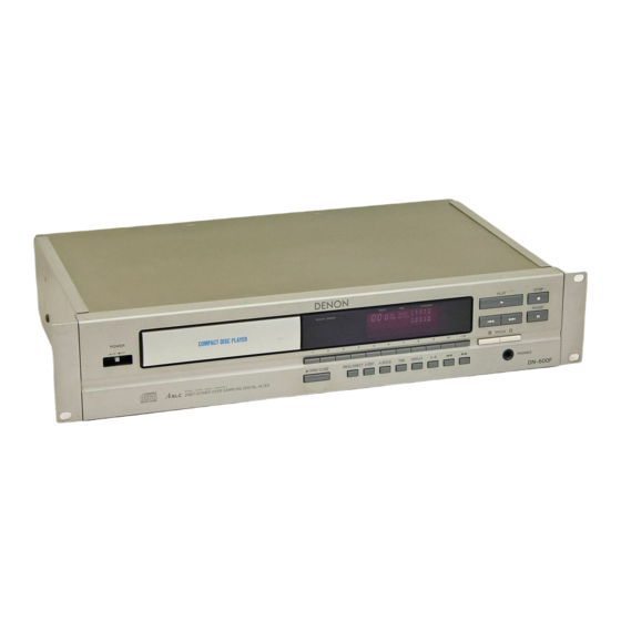
DENON
SERVICE MANUAL
MODEL
DN-6OOF
STEREO
CD PLAYER
-- TABLE OF CONTENTS --
............................................................................
2
.....................................................
3, 4
..............................................................................
5
..............................................................................
6-- 9
.................................................................
10
...................................................................
11 - 14
.......................................................................
14
....................................................................
15
.....................................................................
16
.......................................................
t6
...............................................................
16
............................................................................
17
.........................................................
18
....................................................
18
..................................................................................
19
............................................................................
20
........................................................................
21
..........................................................................
22
NIPPON
COI_MBIA
CO.. LTD.
Advertisement
Table of Contents

Subscribe to Our Youtube Channel
Related Manuals for Denon Nippon DN-600F


Summary of Contents for Denon Nippon DN-600F
-
Page 1: Table Of Contents
DENON SERVICE MANUAL DN-6OOF MODEL STEREO CD PLAYER -- TABLE OF CONTENTS -- SPECIFICATIONS ................NOTE HANDLING OF LASER PICK-UP ............. 3, 4 DISASSEMBLY ................ADJUSTMEN-[ ................6-- 9 HFAT RUN MODE FUNCTION ..............IC TERMINAL FUNCTION ..............11 - 14... -
Page 2: Specifications
III DN-6OOF SPECIFICATIONS FUNCTIONS DISPLAY - -AUDIO ..Functions: Automatic search, progra.mmed No.of.Chan_ neJs::.io_.. _. ' _2 channels- playback, repeat playback, Frequency Respon'_e: 2 - 20,000 Hz. . manual search, auto space, --Dynamic Range: _ _ --98 dB " time mode, auto edit. Signa!rto-noise Ratio:- 107 dB:"... -
Page 3: Note For Handling Of Laser Pick-Up
NOTE FOR HANDLING OF LASER PICK-UP Caution for Handling the Laser Pick-up 4. Metal Bearing The laser pick-up KSS-240A is assembled and precisely adjusted As the metal bearing of Cu-compound sintered alloy is impregnated using a sophisticated manufacturing process in our plant• Do not with FROIL946P (*Part No. - Page 4 NOTE FOR HANDLING OF LASER PICK-UP DESCRIPTION OF THE COMPONENTS +Z-axis direction +X-axis direction Double axes cover Object lens OP Slide base Slide rack LO2 Flexible board Label +Y-axis direction Z-axis Flexible fiat cable connecter (Tangential direction) Y-axis X-axis (Radial direction) year (last figure) -LABEL...
-
Page 5: Disassembly
I I_llV-ldLlUl- IDISASSEMBLY Screw ,DTOP COVER Top Cover Remove 4 screws from both sides and 1 screw from Back Panel. Screw Screw • FRONT PANEL 1. Pull Loader frame frontward, and remove loader panel. Screw Loader Panel 2. Remove 2 front panel upper screws. 3. -
Page 6: Adjustmen
ON-6OOF ,ADJUSTMENT k, l icrocomputer built in the unit, comprises service program to facilitate servo adjustment by pushing operation button. 1. Start service-program (1) Turn power s_tch OFF. - (2) Shortcircuit pin (_ [SWCL) and (_ pin (SWOP) of connector (TP102) on RW.B. (Main Unit) (Caution) Do not touch other pins. - Page 7 ii_P i _il. L.--JLj LJ it- mmmm :2) Necessary equipment for adjustment 1. Dual tracie oscilloscope 2. Reference disc (CA-1094) (Main unit) 33 k_Q Output 3. Oscillator (10 Hz,-- 10 kHz, 0 - 3 Vp-p) Input 0.091 pF (Oscilloscope) 4. Frequen,?_._ounte_r (_r_adable no less than 5 KHz) 5.
- Page 8 I1,_11 | %11 , , Q II,,,J U It-- 5. Tracking gain Connection Oscilloscope Main Unit Counter Filter TP101- (_) (TEO) TP101- (TEl) Oscillator ..T,P.t01.:.® (VC) 0 • Caution: Connect oscillator afterhl PAUSE] pushed and sewo function started Check Oscillator Counter Oscilloscope Adjust...
- Page 9 nN-6OOF 6. Tracking offset (E/F Balance) Connection Oscilloscope Main Unit Filter TP101- O (TEO) O I TP101- O (VC) Check Osciloscope Step (Oscilloscope) 1. Push OPENICLOSE] and load dsc hoMer referrence disk. 2. Push Am OPEN/CLOSE ] and close, holder. 3.
-
Page 10: Hfat Run Mode Function
ON-6OOF HEAT RUN MODE FUNCTION Heat Run Mode To activate While hold pushin"-g DH_, _1_, _ and _ keys simultaneously, turn the unit power on. The remote control sensor indicator will light to show that _e unit i¢ shifted in Heat Run mode. Be sure to Ioadthe disc previously. -
Page 11: Ic Terminal Function
I ON-6OOF IC TERMINAL FUNCTION LIST CXD2500BQ Terminal Function Terminal Function Terminal Symbol lnp.ut terminal for OK focussing. Use for Servo-autosequencer. " Output to shift time constant of output filter for spindle motor. ON/OFF control output for spindle motor. Servo control for spindle motor. Servo control for spindle motor.. - Page 12 ON-BOOF Terminal Function rminal Symbol GND. XTAI X'tal oscillation circuit input. By selecting of mode, f=16.9344MHz or 33.8688MIqz. XTAO X'tal oscillation circuit input, f=t6.9344MHz. XTSL Selection input terminal of X'tal. "L" for X'ta116.9344MHz; H for 33.8688MHz. FS-Ui- 2/3 Dividing output of 53 and 54 terminal.
- Page 13 nN.6OOF C;XA1372S Terminal Function Terminal Function l-erminal Symbol Tracking error signal input terminal. TDFCT Capacitor connecting terminal for time constant at the time of defect ATSC Input terminal of ATSC detecting window comparator. Input terminal of focus zero-cross comparator. Focus error signal input...
-
Page 14: Note For Parts List
ON,.6OOF € CXA1372S _ g° _= < _,d, XRST C OUT TA-- SEN S D G,_D A VCC MIRF' TG:! ,TGU DFCI" ,SRCH ASY ( EFkl ! FOK ! , FEO -Ill: I:Z- I J FS5 cc 2 1 I VC D VCC I NOTE FOR PARTS LIST •... -
Page 15: Parts List Of Rw.board
QN.6OOF PARTS LIST OF P.W.BOARD 3U-2599 MAIN UNIT Remarks Ref. No. Part No. Part Name Remarks Ref. No. Part No. Part Name Ref. No. I Part No. Part Name Remarks CE04W1V330MT 2539039 906 CK45=1 EIO4ZT C509,510 254 4258934 Electrotytic33pF/35V C117 Ceramic0.1p.F/25V SEMICONDUCTOR GROUP... -
Page 16: Packing & Accessories
UNI_U_ llIllll IIIIII IIIII PACKING & ACCESSORIES PARTS LIST OF PACKING & ACCESSORIES PARTS LIST OF EXPLODED VIEW Ref. No. Part No. Part Name Remarks Ref. No, Part No. Part Name Remarks O'ty 504 0092060 STYRENEPAPER ForACCord r-- 1 3u-2599 MAINUNITASS'Y 504 0170005 PROTECTORSHEET... -
Page 17: Exploded View
DN-6OOF EXPLODED VIEW Multi Voltoge Model Only L____ MultiVoltage Model0nly i ° WARNING: Parts marked with this symbol z_ _ have critical characteristics. Use ONLY replacement parts recommended by the manufacturer. -
Page 18: Parts List C,F Fg-70 Mechanism Unit
DN-6OOF EXPLODED VIEW OF FG-70 MECHANISM UNIT PARTS LIST OF FG-70 MECHANISM UNIT Ref. No. Part .No Part Name Remarks 9KA90H006 FS FIXINGSCREW 9KA9OH005 FEEDSHAFT 9KA80G0 17 DRIVEGEAR(A) 9KA80G0 18 DRIVEGEAR(B) 4990191 009 LASERP.U KSS-240A 9KS01Wl 47 LEAFSWITCH 9KA85P009 MOTORP.W.B. 0090051 001 12P FFCCABLE 443 1093006... -
Page 19: P.w.board
,..................nN.6OOF P.W.BOARD 3U-2599 MAIN UNIT $608... -
Page 20: Wiring Diagram
ON-6OOF WIRING DIAGRAM 3U-2599-2 KEY DISPLAY UNIT G1 G2 G3 G4 G5 G6 07 CC604 CC605 _'J _J _'_ "" "" "/ "" " " ") "' l FL DISPLAY ON/OFF SBX1610-52 F1 IN ,,", ,,',, r,, t",, FIPBNM6A ," ,, r', F1 OUT REMOTE UNIT... -
Page 21: Schematic Oiagram
I DN-6OOF SCHEMATIC DIAGRAM JACK701 3U - 259 8 - I IT°°Llj.Zm o • T • 43130292'8272625242'3222 II10 ,kl,k,t_,k_,k.t..t..k_.,k,k,L,',,ti_,i,L..k,kI,.,,,,,_ 2.1 ..1T RANS J__c_oI lli_..K_ " CB602 COIRI) u Lv_L> I r' _ _ _ _ z_ > - o., ,.,., ®... -
Page 22: Semiconductors
DN-6OOF SEMICONDUCTORS • IC's • IC DIODE • IC PROTECTOR SM5841BP TL4558P :RC4558P OKSL IT" "_DIN XTI I-_ BCKI A OUTPUT I_v I[_] V+ ___= XTO I_- LRCI A-,NPUT X--I BOUTPUT CKOI-Z BCKO lSS198 A+,NPOT__ B-,NPUT vss E 1SS270A =--p ÷,NPUT MOT E WCKO lSR35... - Page 23 DN-6OOF...
- Page 24 NIPPON COLUMBIA CO.. LTD. 14-14, AKASAKA 4-CHOME, MINATO-KU, TOKYO 107-I 1, ,JAPAN Telephone: 03 (3584) 8111 Cable: NIPPON COLUMBIA TOKYO Telex: JAPANOLA J22591 Printed Jr,Japan 407 _B_ 0438...
Need help?
Do you have a question about the Nippon DN-600F and is the answer not in the manual?
Questions and answers