Table of Contents
Advertisement
EXTRA
BELT
EXTRA
PAPER
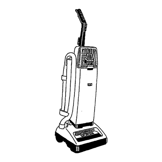
Dimension
TM
Upright
The Dimension"
Upright series of cleaners was
first introduced in mid-1994 as replacements
for
Legacy models.
Fig. 1.
All models were introduced initially with:
97
1
Fig. 2
Fig, 3
Fig. 6
Fig. 5 l_
POSITION
#5
Oo_ ,,.%_;0°_
l ,_ ZOR POSITION
R
I _
OF VALVE-_ !
=='_'-_
I GATE/F "--_
•.
,-
-
AGITATOR
II
•
VALVE GATE IN CAVITY
VALVE GATE IN
CARPET
HEIGHT
CLEANING
TOOLS
POSITION
Fig. 7
ON/OFF
CORO
SW,TCN
_)
HOOK
CONTROL
TYPE Z
SAG
Libel.
1
,AG
EXTENSION
WAND
;_
CARPE'f
MOTOR
ADJU
BELT
AGITATOR
,, Molded, integral handle grips
• On/Off switch on the front of the upper handle
• Two brush agitator (Replaceable
Roll Sleeve)
• Extra bag and belt storage on the unit Fig. 2
• One 12v headlight
• Hard bag enclosure
• One speed motor
• Stair cleaning handle
• Four position carpet height adjustment Fig. 3
• Top tool conversion
• Triple stretch hose
• Tool storage on the front of the unit
• One molded extension wand
• Type Z mlcrofiltratlen
throw away bags
Some models have a "check bag" indicator on the
outside of the bag door. Fig, 4
The cleaning tool hose attaches to the cleaner
through the top of the hood and CAN stay attached
at all times.
When using cleaning tools, the nozzle control must
be in the #5 cleaning tools position. Fig, 5
With the nozzle control in the number 5 position, a
valve gate in the main body closes and blocks all air
flow from the agitator cavity therefore diverting it to
the hose.
Set on carpet, positions 1-4, the gate valve is
opened allowing air to flow from the agitator cavity
to the motor. Fig, 6
To ensure maximum efficiency in the 4 floor cleaning
positions .b_o_Lb_
hose ends must be firmly connected
to the cleaner base and tool rack Fig, 7 or the hose
removed completely and the tool door closed.
Refer to the Hoover Service Manual for repair proce
dures and the Microfiche Parts Catalog - light brown
header - for spare parts.
Advertisement
Table of Contents
Troubleshooting

Related Manuals for Hoover Dimension


Summary of Contents for Hoover Dimension
- Page 1 Fig, 7 or the hose removed completely and the tool door closed. WAND CARPE'f MOTOR Refer to the Hoover Service Manual for repair proce ADJU BELT dures and the Microfiche Parts Catalog - light brown header - for spare parts.
- Page 2 SERVICE INSTRUCTIONS LEGACY, LEGACY II, DIMENSION & DIRT FINDER CLEANERS Selv_ce Dept. 1/96...
- Page 3 Legacy/Legacy SWITCH CONTROL BUTTON LOWER JACKET SUPPORTLOWER REAR WHEEL CAM ACTUATOR IPRING...
- Page 4 Legacy - Hard Bag fBAO TOOL DOOR BPRING UPPl_ TOOL RACK MOTOR RETAINER LH • MOTOR RETAINER RH HANDLE BIJI.B I KNOll , WHEEL 8HAFT NOZZLE HEIGHT WHEEL FRONT WHEEL* AGITATOR. ROITOM PLATIi...
- Page 5 Dimension THROW AWAY BAG TOOL DOOR UPPER TOOL DOOR RPBING HOOD LENB IPPF..JROD LOWER HANDLE .TOOL MOTOR RETA)NER-RH MOTOR BULB HANDLE LEVER HOUBINO -- MAIN BODY VALVE GATE WHEEl. SUPPORT AQ.ATOR...
- Page 6 Dirt Finder - Circuit Board Switch Battery Battery Microphone- cover Note; Only the components that distinguish the Dirt Finder unit from the Dimension are listed.
- Page 7 I. General These uprights are lightweight upright vacuums that feature high performance computer design motors, double edge cleaning, quick release cord wraps and top conversion cleaning tools ON/OFF SWITCH All models have automatic height adjustment that the nozzle is free to float up and down on the Fig.
- Page 8 III. Disassembly Models with a bag door skip to section A. Outer bag (Legacy and Legacy II Models) As the lever is movedto the cleaningtools position the cam locks on to the gate and slides it to shut off suctionto the agitatorcavity. 1.
- Page 9 Fig. 3 UEO_CY II DiMENS,_N Fig. 5B 2. Remove throw-away bag, 3, Remove bag housing. a. Release two tabs on inside of bag housing located above dirt tube (Fig. 5C) Fig. 4 t/ 4. Remove outer bag. Note: Re-assemble in reverse order.
- Page 10 Fig. 5E b. Lift bag housing out of bag housing bracket located on lower handle. (Fig. 5F) Fig SH D. Switch 1. Disconnect leads and snap switch out of bag housing. E. Circuit Board Fig. 5F 1. Remove housing screws. C.
- Page 11 2. Locate and release the two retention tabs for the 2. Disconnect leads at board (Fig 51) cap on the inside of the jacket. (Fig. 6). Fig. 6 3. Remove cap. I. Jacket support - upper (Legacy, Legacy F_.61 models without air freshener dispenser).
- Page 12 Flg. 9 1, Remove attachment cord. 3. Remove bag housing (where applicable) a. Slide cord protector and connector out of handle 4. Remove retaining screw located on the back of upon re-assembly, be sure to align the arrow on the handle and remove rack.
- Page 13 The lowerrib of the switchcontrol rod is taperedas shownin Fig. 13. This protrusionmust be raised to clearthe supportrib in the lower handle(Fig.13) in orderto facilitateremoval. Fig. 15 NOTE:Early model LegacyII lower handle assemblyincludesan integralmuffler system. This M. Hood systemconsistsof a muffler louver,muffler foam and a muffler cover.All of these items 1.
- Page 14 Headlight lens/panel For instructions concerning the agitator agitator section The headlight lens and/or panels are removable eleasing the retention tabs as illustrated (Fig. 18) Q. Front wheel supportJwheels/lever 1. Remove bottom plate Fig. 18 2. Release the cam actuator spring from the front wheel support retaining...
- Page 15 4. Remove hood 5. Release the 2 nozzle height adjustment retention tabs (Fig. 24) E'LRLY _T_ST The early design wheel supports are no longer available in service. Updating the unit from the early style support to the latest will require replacement of the main body.
- Page 16 4. Remove the molded duct seal by sliding it off the housings V. Motor assembly 5. Lift off fan chamber and remove fan (LH thread) 1. Remove handle. At this point, you have broken a latex paint seal 2. Remove hood. between the motor housing and fan chamber...
- Page 17 MOLDED DUCT SWITCH FAN CHAMBER MOTOR END CAP ASSEMBLY •" MOTOR BRUSH HOLDER ASSEMBLY Onloff switch 7. Remove switch by releasing switch pressure tabs and snapping switch out of holder. 1. Remove fan. 2. Remove brush holders. 3. Remove armature, 4.
- Page 18 Troubleshooting check list - Legacy/Legacy II/Dimension/Dirt Finder -he following is a guide to aid in determining the origin of a problem for which these models could conceivably .Jrought in for service. PROBLEM POSSIBLE CAUSE POSSIBLE SOLUTION A. Motor won't 1. Not firmly plugged in. 1.
- Page 19 This section addresses problems associated with the Dirt Finder feature in the Dirt Finder unit PROBLEM POSSIBLE CAUSE POSSIBLE SOLUTION A. Circuit board 1. 9V battery not installed. 1. Install battery and check operation. won't light 2. Low battery. 2. Change battery.
- Page 20 Troubleshooting Guide Legacy & Legacy II...
- Page 21 The following Js a guide to aid in determining the origin of a problem for which these models could conceivably be brought in for service PROBLEM POSSIBLE CAUSE POSSIBLE SOLUTION A. Motor won't Check power cord for proper connections Not firmly plugged in Plug into known good voltage source No voltage in customer's wall plug On/off switch bad...
- Page 22 Fan chamber or cover cracked. Replace. H Belts Off brand belt being used. Install genuine Hoover belt and check. continually Agitator"dragging" Check for worn agitator bearings, worn or missing breaking. thrust washers and thread or carpet fiber built up under thread guards.