
Related Manuals for Aiwa D33


Summary of Contents for Aiwa D33
- Page 1 English alluLIra SERVICE SERVICE MANUAL VIDEO MECHANISM TYPE I P2 LRN 106A P4 LRN 133A alluura S/M Code No. 09-99B-336-8N2...
-
Page 2: Table Of Contents
TABLE OF CONTENTS REMOVING CASSE'FrE MANUALLY ......3 DECK MECHANISM ADJUSTMENT DECK MECHANISM PARTS LOCATIONS Tools and Fixtures for service ......... Top View ................1. Mechanism Alignment PositionCheck ......17 Bottom View ..............2. Preparation for Adjustment ......... DECK MECHANISM DISASSEMBLY 3. -
Page 3: Removing Casse'fre Manually
REMOVING CASSETTE MANUALLY 1. Remove the loading motor. 3. Turn the capstan belt to take up slacktape. Capstan belt , etC. Fig. 1 Fig. 3 2. Turn the gear connect in the direction of the arrow 4. Turn the gear connect in the direction of the arrow with you finger to perform unsledding. -
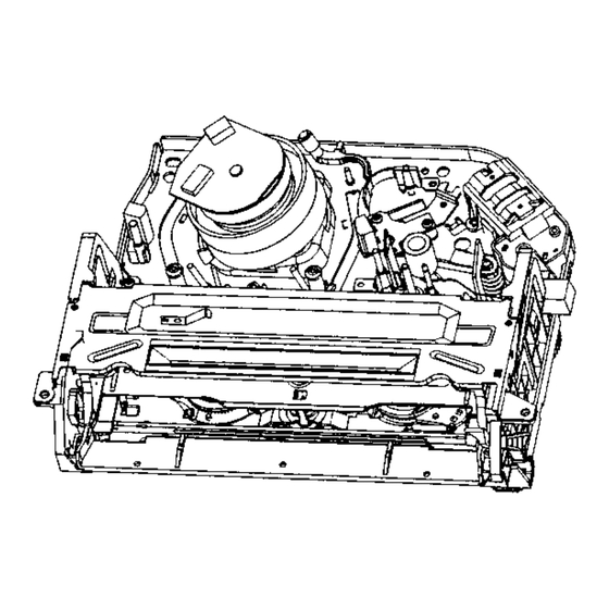
Page 4: Top View
DECK MECHANISM PARTS LOCATIONS • Top View Jgre Part _4arblla_- Fixing Type 1 _Drum/,.ssar_ 3Sae_s,Cap FPC Two Ho_s _-21 2 FUe _y Chas_Ho_ 6-21 3 Hdder _mbly CST 2Hod_ 6-2 I 4 Gu_e C ST l$oew 5 _'_et Side(L) 1Soew Z3,4 6 Brad_t_e_tly Do_ Z3.43_... -
Page 5: Deck Mechanism Disassembly
DECK MECHANISM DISASSEMBLY b(Sl) lit Optiorull Paris (Sl) (only Ic_ 2HD Models) (only for 4HD_A<_O Models) (only fo_4HD4-1i_i Models) Holder FPC or Holdl_ FPC or Holder FPC .___< Fig. A-1 1. Drum Assembly (Fig, A-1-1) (Fig. B-l) 1) Unhook the (H1) on the back side of the Chassis and separate the Cap FPC, 2) Remove three... - Page 6 DECK MECHANISM DISASSEMBLY Plate Assembly Top (Fig, A-2-1) Holder Assembly CST Lever Stopper (L) Lever Stopper (R) (Fig. A-2-2) Arm Assembly F/L (Fig. A-2-6) (S2) LeverAssembly S/W (Fig. A-2-7) Bracket Side (L) ($1) (Fig. A-2-4) Groove Gear Rack F/L Groove Guide CST (Fig.
-
Page 7: Plate Assembly Top
DECK MECHANISM DISASSEMBLY 2) Remove the Screw ($2) and d=sassemble the Bracket 2. Plate Assembly Top (Fig. A-2-1) Assembly Door in the front 1) Unhook the (H1) and separate the Left S=de 6. Arm Assembly F/L (Fig. A-2-6) 2) Unhook the (H2) and hftup the Plate Assembly Top 1) Push the Arm Assembly F/L to the left and hftup it NOTE NOTE... -
Page 8: Arm Assembly Cleaner
DECK MECHANISM DISASSEMBLY Arm Assembly Cleaner \\(Fig. A-3-1) (s,) \ Base AssemblyA/C Head (Fig, A-3-3) (H1) _ (Fig. A-3-2) _\'_i Head F/EJ Fig. A-3 8. Arm Assembly Cleaner(Fig. A-3-1) 9. Head F/E (Fig. A-3-2) 1) Break away the (A) part shown above Fig, A-3-1 from the 1) Unhook the two Hooks (H1) on the back side of the... -
Page 9: Brakeassembly S
DECK MECHANISM DISASSEMBLY Spring S Brake _.-_ BrakeAssemblyS _"_"(A) (Fig. A-4-1) Arm Assembly Tension Sprlnl ='C; __'_ _=_ Reel T (Fig. A-4 3) ///---- AWnn_ib/Y Spring T Brake Reel S \ " ,_ (Fig. A-4-4), Fig. A-4 11. Brake Assembly S (Fig. -
Page 10: Supportcst
DECK MECHANISM DISASSEMBLY • - - \ ,, , , Opener U d (Fig. A-5-3) "_ Spring\ _ Arm T/Up \ Arm AssemblyT/up "_, Assembly Base AssemblyP4 Pinch SupportCST (Fig. A-5-1 ..(Fig. A-5-2) Fig. A-5 15. Support CST (Fig. A-5-1) 2) Lift up the Arm AssemblyT/up 1) Break away the (A) part shown above Fig A-5-1 from the NOTE... -
Page 11: Belt Capstan/Motor Capstan
DECK MECHANISM DISASSEMBLY (Fig. A-6-1) (B).., Motor Capstan (A),:_ Washer(W1 (Fig. A-6-2) (Fig. A-6-3) Clutch Assembly Washer(W2) ltr Opbonal Parts Lever F/R I _'_;_ Gear Assembly H-Up/D Gear Assembly Up/D II¢;N A.J_I_ I_---- {ForH_-RewmdModels_ _(ForNormalModels) HOOk(H1) (c) ___ -_ \"' '_,_- (Fig. -
Page 12: Bracketassembly Jog
DECK MECHANISM DISASSEMBLY Brake Assembly Capstan Brake Assembly Capstan Gear Can (H2) (Fig. A-7-4) Hole Guide Rack F/L (if1)\ (st) BracketAssembly Jog A-7-1) Gear Rack F_ Gear Fig. A-7 24. Bracket Assembly Jog (Fig. A-7-1) 1) Remove the Screw(S1) and lift up the Bracket Assembly •... -
Page 13: Gear Drive/Gear Cam/Gear Connector
DECK MECHANISM DISASSEMBLY _._,, Washer(W1) Gear Cam (Fig. A-8-2) Gear Connector (Fig. A-8-3) .IZS Gear Connector Hole(A')+(A) Chassis Bracket Assembly L/D Motor Hole(B')+(B) Gear Cam Fig. A-8 (Fig. B-3) 27. Gear Drive (Fig. A-8-1)/ Gear Cam (Fig. A-8-2)/ Gear Connector (Fig, A-8-3) Gear Cam (C) Remove the Washer(W1) -
Page 14: Gear Sector
DECK MECHANISM DISASSEMBLY 29. Gear Sector (Fig. A-9-1) NOTE 1) Remove the Washer(W1) and lift up the Gear Sector 30. Base Tension (Fig. A-9-2)1 (1) When reassembhng,turn the Lever Tension to the clock- wise d_rect_on m maximum Plate Slider (Fig. A-9-3)/ Lever Tension (Fig, A-9-4) I) Remove the Screw(S1) and h11 u p the Base "Tension... -
Page 15: Gear Assembly P3/Gear Assembly P2
DECK MECHANISM DISASSEMBLY (A) ' 1_ Optional Parts Arm AssemblyIdler or Arm AssemblyIdler Jog (For2HD Models) (For4HD Models) "x "_ (Fig. A-10-5) (H3) (Fig, A-10-3) ,_ Base Assembly Fig. A-10 NOTE 31. Gear Assembly P3 (Rg. A-10-1)/ Gear Assembly P2 (Rg. A-10-2) 1) An'nAss_nbly Idler Jog m for 4HD Models 1) Unhook the two Hooks(H1) and I_ up 1he Gear _ 2) Arm Assembly Idler _ for 2HD Models... -
Page 16: Deck Mechanism Adjustment
DECK MECHANISM ADJUSTMENT • Tools and Fixtures for Service 1. Cassette Torque meter 2. Alignment tape 3. Torque gauge SRK-VHT-303(Not SVC part) 600g.Cm ATG (See figure below) 4. Torque gauge adaptor 5. Poet height ad|usting driver 6. + Type driver (o 5) Parts No: SV-TGO-030-000 (SMALL) SV-TGO-020-000 (LARGE) -
Page 17: Mechanism Alignment Positioncheck
DECK MECHANISM ADJUSTMENT 1.Mechanism Alignment Position Check Purpose:To determine if the Mechanism is in the correct position, when a Tape is ejected. Test Equipment/Fixture Test Conditions (Mechanism Condition) Check Point • Blank tape • EjectMode (with Cassetteejected) • Mechar_sm a ndMode Switch 1) Turn the Power SAN on and eject the Cassette by press- with the Gear Drive as below Fig. -
Page 18: Preparation For Adjustment
DECK MECHANISM ADJUSTMENT 2. Preparation for Adjustment (To set the CassettewithoutTape Cover the Holes of the End SensorSat the bath sales of the Deck Mechanism to the Loading state BracketS=de(L)and BracketAssembly Door to preventa without inserting a Cassette Tape). light leak 1) Unplugthe Power Cordfrom the AC Outlet Then The Deck Mechanismdnvesto the Stop Mode 2) Dtsassemble the TopCoverand Plate AssemblyTop... -
Page 19: Guide Roller Height Adjustment
DECK MECHANISM ADJUSTMENT 4.Guide Roller Height Adjustment Purpose: To regulate the Height of the Tape so that the Bottom of the Tape runs along Tape Guide on the Lower Drum. 4-1. Preliminary Adjustment Test Conditions (Mechanism Condition) I Test Equipment/Fixture Adjustment Point •... -
Page 20: Audio/Control(A/C) Head Adjustment
DECK MECHANISM ADJUSTMENT 5. Audio/Control (A/C) Head Adjustment Purpose: To insure that the Tape passes accurately Alignment in both the Record and Playback Modes. over the Audio and Control Tracks in exact I 5-1. Preliminary Adjustment (Height and Tilt Adjustment) Perform the Preliminary Adjustment, when there is no Audio Output... -
Page 21: The Take-Up Guide And Pinch Roller
DECK MECHANISM ADJUSTMENT slowly turn the "nit Adlustment Screw(C) in the 5-2. Confirm that the Tape passes smoothly Counterclockwtse dtrecbon between the Take-up Guide and Pinch Roller(using a Mirror or the naked eye). Afetr completing Step 5-1 (Prehmmary Adjustment). NOTE: check that the Tape passes around the Take-up Gu=de and Pinch Roller wrthoutFoldingor Cudmg at the Top or Check the RF Envelope after adjusting the A/C Head, if... -
Page 22: (Video Heads)
DECK MECHANISM ADJUSTMENT Adjustment after Replacing Drum Assembly (Video Heads) Purpose: To correct for shift in the Roller Guide and X value after replacing the Drum, Test Conditions Test Equipment/F'_ture ConnecbonPoint (Mechanism Condition) Adjustment Points • Osollescope • CH-1 PB RF Envelope •... -
Page 23: Maintenance/Inspection Procedure
MAINTENANCE/INSPECTION PROCEDURE 1 Check before starting repairs The following faults can be remedied by cleaning and oiling Check the needed lubncahon and the conditions of cleanli- ness in the und Check wdh the customer to find Out how often the unit ts used, and then determine that the unit is ready for inspection and maintenance. -
Page 24: Required Maintenance
MAINTENANCF_JINSPECTIONPROCEDURE 2. Required Maintenance 4. Supplies Required for Inspection and Maintence The recording density of a VCR(VCP) is much higher than that of an audio tape recorder. VCR(VCP) components must (1) Grease : Kanto G-311G (Blue) or eo_ivaJent be very precise, at tolerances of l/lO00mm, to ensure com- (2) Isopropyl Alcohol or equivalent patiblity with other VCRs. -
Page 25: Greasing
MAINTENANCE/INSPECTION PROCEDURE (2) Periodic greasing 5-2) Greasing Grease specified locations every 5,000 hours. (1) Greasing guidelines Apply grease, with a cleaning patch. Do not use excess 1) LoadingPath Inside & Topside 5) LeverTensionGroove grease. It may come into contact with the tape transport 2) Shaft 6) Cinch Assem_yD33 Shaft or drive system. -
Page 26: Deck Mechanism
MECHANISM TROUBLESHOOTING GUIDE 1.Deck Mechanism of supply side "H"? "H": more than 3.5V Is the output of END sensor "L": less than 0.7V~IV Iklt"t I '11 _,/ Is the Vcc. voltage of End sensor 5V? Check the syscon power. Replace End sensor. Is the voltage across IR LED Replace LED. -
Page 27: Mechanism Troubleshooting Guide
MECHANISM TROUBLESHOOTING GUIDE Check aligmentpositions(page 17) Check spdngPinch._._ __ roller in contact with the capstan Replace Drum Motor. In Ptay/cue/Rev is the pinch _,.[ shaft. Is the outputof DFG, DPG OK? puAreses.there T/up and supply reel Check Servo, Syscon. Check the Syscon, I_-COM. •I_-[ Replaoe Reel Sensor. - Page 28 MECHANISM TROUBLESHOOTING GUIDE In pB mode Tape Presence not sensed. Check Alignment positions Is the Pinch Roller attached to the Capstan Motor Shaft? (page 17) Does the T/Up Replace the Bell Reel turn? is the Belt ok? ,Es ! Check the clutchand the Idler I Does the Capstan Motor turn? Assembly, YES !
-
Page 29: Front Loading Mechanism
MECHANISM TROUBLESHOOTING GUIDE 2. Front Loading Mechanism Is the Lever Switch Spring Replace or add the oes the Lever Switch work? damaged or omitted? Lever Switch Spring. Replace F/L Switch. Does the F/L switch work normally? YES _ _sthe Vcc of Main P.C,Board syscon Check circuit. - Page 30 MECHANISM TROUBLESHOOTING GUIDE Does the L/D motor rotate in reverse? Check L/D Motor or Drive IC. Does the Lever Switch work? " I Replace lever Switch. YES ! I _es_°A_ Ass°mb"F'Lw°rk°°n_a"Y? "1 Replace Arm Assembly F/L. YES ! ooestheOpooerDoerwerk? "1 Replace the Opener Door.
- Page 31 MECHANISM TROUBLESHOOTING GUIDE Does the CST insert? Does the opener Lid work? Does the Gear Rack F/L work? Replace the Opener Lid. Does the Opener Door work? Replace the Rear Rack F/L. [ NO Ooo°,hoA_ A_,om0, F_wo_ Is'he°0°n°r O°°r _ss°_ °°_e°*Y_l I I.°...
-
Page 32: Mechanism Exploded View 1/3
-_'_" i P4 ONLY ... 2 -_ P2 ONLY... -
Page 33: Mechanism Main Parts List 1/3
MECHANISM MAIN PARTS LIST 1/3 I_]r;SCRIVFI( ),N÷C'_IF_-_ _ ?_ _"_'_yJ(_ ''R£FERENCE N'NME LI'c'T:' L T < f_ _ _ _o _trst:lndforl)e_crDtiOllllezlsek _ vrefer [fcall'tL J"REFERENCEN,%MELST"] R£F. NO PARTNO. KANRI DESCRIPTION SI-41R-000-2A0 CHASSIS ASEY E2 61R=000-gA0 A_M ASSY IDLEE-J<P4> $2 61R 000-8A0 ARM ASSY IDLER-J<P2>... -
Page 34: Mechanism Exploded View 2/3
> LEVER P3 SPRIN( GEAR P2 < LEVER P2 CAPSTAN P4 ONLY BRAKE "-"BRACKET JOG ',... -
Page 35: Mechanism Main Parts List 2/3
MECHANISM MAIN PARTS LIST 2/3 DESCRII:'TION_J_r_ _ ta: _ _t_._Jt:_ "REFERENCE NAME LIST" (. -C < P-c _ _o f call t tin_ erstail{ Descr Pt on D ease khl_ y refer P_.FEREN(E NAb, E LIST REF,NO PAR'[NO KANR) DESCR_'[_'_ Sg-TOR-005-1A0 SPRING UP/D S4-70R-004-4A0... -
Page 36: Mechanism Exploded View 3/3
"U < BRACKET _(R) OPENER DOOR... -
Page 37: Mechanism Main Parts List 3/3
MECHANISM MAIN PARTS LIST 3/3 DESCRIPTIONq2'_JII_-C_rIg:I, _,113. "REFERENCE NAME LIST' .'_,_.,_,. L.-L- < p._ I,_o If c_an t u1_derstand for Descr pt on please k ndly refer to " REFERENCE NAME LIST". J REF, N O P/_RT N O. KANRI 0ESG_PNON 1 S5-10R-002-0A0 LEVERSWITCH 2 S9-70R-005-0A0 SPRING SWITCH... - Page 38 AIWA ---CO.. ---LTD. 2 -11, .KE.O.ATA 1-C.OME. TA,TO-KU, TOKYO 110-8710. JAPA. TEL:03 138271 931261 Printed in U.S.A.
Need help?
Do you have a question about the D33 and is the answer not in the manual?
Questions and answers