
Subscribe to Our Youtube Channel
Related Manuals for EverAccess EFC--02-1-A

Summary of Contents for EverAccess EFC--02-1-A
- Page 1 EverAccess User Manual Volume...
-
Page 2: Instruction Guide
1801 Highland Ave Duarte CA 91010 Phone 626.844.8888 • Fax 626.844.8838 All rights reserved. No part of the contents of this manual may be reproduced or transmitted in any form or by any means without written permission of the Everfocus Electronics Corporation. -
Page 3: Table Of Contents
Table of Contents CHAPTER 1 Product Overview Features Parts List Controller Layout Installation Review Preparing for the Installation Obtain a Floor Plan Determining the Hardware and Location Determining System Structure as well as the Number of Controller and Modules 7 CHAPTER 2 Hardware Installation Mounting the Enclosure and Controller... - Page 4 CHAPTER 3 Connecting Controller to Computer Connection to Computer via RS232 Connection to Desktop Reader via RS485 RS485 Bus Based Networking System RS485 Bus Extension Connection to Multiple Controllers via RS485 TCP/IP Based System CHAPTER 4 Connecting Power Connection to Power Supply Mount a Backup Battery in the Enclosure (Optional) Connection to Backup Battery Reset Controller...
- Page 5 Delete Cards Delete a Card by Serial Number Delete All Cards Set Card Properties Status Setting Access Right Setting Group Setting Set Card PIN Setting Anti Passback (APB) Setting Card ARM Setting Show Card Number Reader Setting Enter Reader Setting Menu Keypad Setting Reader to Door Allocation System Reader Setting...
- Page 6 Invalid Time Card Anti-Passback Fail Card PIN Fail Door Forced Open Door Held Open Reader Lost Enter Alarm Time Setting Sub-menu Armzone Setting Enter Armzone Setting Menu Set Active Armzone Set ARM Delay Time Address Setting ARM/DISARM ARM The System using the Controller Keypad Disarm the System using the Controller Keypad Clear the Alarm Arm/Disarm the system using a reader...
-
Page 7: Specifications
Specifications Items Maximum cards Maximum records Supported readers Maximum controllers connected via RS Controlled doors Communication format Cardholder PIN System PIN ARM PIN Alarm input Alarm output Communication ports Band rate Programmable duration Programmable date Access group Card Expiration Auto day-light saving Anti-passback Build-in keypad LCD screen... -
Page 8: Federal Communication Commission
Federal Communication Commission Interference Statement This equipment has been tested and found to comply with the limits for a Class B digital device, pursuant to Part 15 of the FCC Rules. These limits are designed to provide reasonable protection against harmful interference in a residential installation. This equipment generates, uses and can radiate radio frequency energy and, if not installed and used in accordance with the instructions, may cause harmful interference to radio communications. -
Page 9: Product Overview
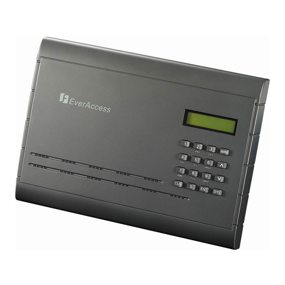
Product Overview EverAccess® Flex Series controller (part number: EFC-02-1A) incorporates state-of- the-art technology and modular design to provide reliable performance, user-friendly installation, expansion capabilities, and flexible but powerful configuration options. This controller is the ideal solution for any application that requires electronic access control. -
Page 10: Parts List
Please Note: If an item appears to have been damaged in shipment, replace it properly in its carton and notify the shipper. If any items are missing, notify your Everfocus Electronics Corp. Sales Representative or Customer Service. The shipping carton is the safest container in which the unit may be transported. Save it for possible future use. -
Page 11: Controller Layout
Controller Layout Figure 1.1 shows the layout of the EverAccess Flex Series Controller along with its main components and their functions. Terminals on door module alarm module Door module Alarm LEDs on module door module Fig. 1.1 Controller Layout (1) Main module The main module controls the fundamental functions of the controller, including the power supply, event records, communication via RS232 or RS485 port, fire alarm input, a general alarm input and two alarm outputs. - Page 12 (6) Door module Each door module controls up to 2 readers and relays event signals to the main module. (7) Door module terminals The door module terminals provide an interface to peripherals like door sensors, door locks, request-to-exit devices and alarm outputs. Please refer to Ch 2 (p 13) for more details.
-
Page 13: Installation Review
Installation Review The overall installation steps are shown in the following block diagram. The detailed descriptions are given in the subsection below. Step 1: Preparing for the Installation • Obtain a floor plan • Determine the hardware and location • Determine the number of controller and modules and system architecture Step 2: Hardware Installation •... -
Page 14: Preparing For The Installation
Preparing for the Installation Before beginning the installation process, EverAccess recommends that the user properly prepares by gathering certain information. Proper preparation will help ensure a smooth installation, and will save the installer time and hassle in the long run. The following information is essential for a professional installation: Obtain a Floor Plan Obtain a floor plan of the building in which the access control system is to be installed. -
Page 15: Determining System Structure As Well As The Number Of Controller And Modules
Entry Card Readers EverAccess EXIT Request-to-exit Fig. 1.2 A Common Door Configuration with Entry Reader 3. Two readers, entry and exit access control If additional security is needed at a particular door, or if the administrator needs a record of the time and date that people enter AND exit a door. Adding a second reader on the secure side of the door will require people to present a card to exit as well as enter. -
Page 16: Chapter 2 Hardware Installation
Hardware Installation In this chapter, after preparing for the installation, the user is ready to begin the install. This section will describe, in general terms, how to install the hardware. Here are the following processes: • Mount the enclosure (enclosure optional) and controller •... - Page 17 The EverAccess Controller package includes two support frames to elevate the controller in order to make wire connections more convenient. The installation is described in the steps below: Step 1. Mount the two support frames on a wall or on the interior of the EverAccess enclosure.
-
Page 18: Installing A Module To Controller
Step 3 Installing a Module to Controller EverAccess Flex series controller can hook up to 4 door modules and 1 alarm module. Please note only ONE alarm module can be installed to the controller. Each door module is cascaded to its left side module till the main module. The door modules and the alarm module can be placed in any sequence. -
Page 19: Reader/Door Index Conversion
1. Connect the pins on the lower right corner of the new module to the connector on the bottom left corner of the installed module. Make sure that the pins fit snugly into the receiving module. 2. Secure the module to the controller base board using the three screws (provided in the module package). -
Page 20: Main Module Led Definition
Figure 2.3 The main module and its terminals The terminal definitions are shown in the following table. Table 2.1 The Definition of the Main Module Terminals Terminal name Function Alarm In 0 General alarm input 0 Alarm input GND FireIn Fire alarm input Normally open pin of auxiliary AUXAlarmOutNo... -
Page 21: Door Module Terminal Definition
Figure 2.4 Main Module LED Definition Table 2.2 The definition of the LEDs on the main module Meaning The power is on when the light is on Fire alarm when the light is on Data is received when the light is on Data is transmitted when the light is on Door Module Terminal Definition The terminals on the door modules are classified into two groups, each of which... -
Page 22: Door Module Led Definition
Table 2.3 The Definitions of the Door Module Terminals No Terminal name Function 1 Reader1_Data0 Reader 1 Wiegand Data 0 2 Reader1_Data1 Reader 1 Wiegand Data 1 Power supply for reader 1. 3 Reader1_DC Output +12 V voltage. 4 Reader1_GND GND for the Reader 1 5 Reader1_Ctrl Control line for reader 1 6 RX_1... -
Page 23: Alarm Module Terminal Definition
Alarm Module Terminal Definition There are 36 terminals on the alarm module. The positions and indexes are described in Fig 2.7. The definitions are described in Table 2.5. Fig. 2.7 Alarm Module Terminal Definition The definitions of the alarm module terminals are defined in the following table: Table 2.5 The Definition of LEDs on the Alarm Module Terminal Function... -
Page 24: Alarm Module Led Definition
Alarm Module LED Definition There are 8 LED indicators on each door module. The positions and indexes are shown in Fig. 2.8. The definitions of the LED indicators are presented in Table 2.6. Fig. 2.8 Alarm Module LED Definition The definitions of LEDs on the alarm module are defined in the following table: Table 2.6 The Definition of the LED Indication on the Alarm Module Meaning Alarm 1... -
Page 25: Rs232 Format
As mentioned before, every door module can control up to two card readers with the correct wiring. The supported reader formats are EverAccess RS232 and standard Wiegand26. For instructions on connecting each type, please refer to Fig. 2.9 (a) for the RS232 reader connection and Fig 2.9(b) for the Wiegand reader connection. -
Page 26: Connection To Door Lock
Connection to Door Lock Electric strikes and magnetic locks are used to keep doors locked unless the system grants access or the user sets the doors to remain unlocked. The installer must supply the electric strikes and/or magnetic locks. It is recommended that the installer follow and keep the instructions for these locks. -
Page 27: Connection To A Magnetic Lock
Connection to a Magnetic Lock (27) (28) (29) Door module Fig. 2.11 Example for Connecting a Magnetic Lock Terminals 11 ~13 are for Door 1 and terminals 27~29 are for Door 2 connections. Please NOTE: The maximum current outputted by the door lock relay on the door module is less than 5A. -
Page 28: Connection To Request-To-Exit
NOTE: Among these four terminals, terminal 9 and 25 are GND, shared by the door sensor and request-to exit (10 and 26 are your input signals) Connection to Request-to-Exit The door module also provides an interface to the request-to-exit button or sensor. Door 1 is connected to terminals 8-9 and door 2 is connected to terminals 24-25 respectively. -
Page 29: Connection To Alarm Output
Alarm modul Fig.2.14 Connecting Alarm-sensor to Controller Connection to Alarm Output The alarm module provides 8 alarm inputs and 8 alarm outputs. The user can assign the corresponding relay status to the different events. There are three terminals: COM, N.O and N.C. The wiring depends on the alarm device. Please read the user manual of the external alarm devices before wiring. - Page 30 C. termina N.C. terminal Alarm module Fig. 2.16 Normally Closed Connections for Alarm Output 5 External Alarming Device...
-
Page 31: Connecting Controller To Computer
Connecting Controller and Computer Connection to Computer via RS232 The EverAccess controller is able to operate as a stand-alone device or as a networked device, connected directly to a PC via serial port. Figure 3.1 Connecting the Controller to a PC To connect the controller to the computer via RS232, the communication terminals should be wired to the computer serial port as follows: the RS232 TX terminal of the controller is linked to the RS232 RX of the serial port and the RS232 RX terminal is... -
Page 32: Connection To Desktop Reader Via Rs485
Main module Fig. 3.2 Connection to Computer via RS232 Connection to Desktop Reader via RS485 To connect the EverAccess Flex Series controller to the desktop reader via RS485 bus, terminal 10, 11 and 12 on the main module should be wired to the line 1, 2 and 3 in RJ45 head, as Fig 3.3 shows. -
Page 33: Rs485 Bus Extension
system: it allows simple card enrollment and acts as the interface between multiple controllers and the PC. EverAccess PO WER C A R D Figure 3.4 Connections of Multiple Controllers A brief overview of the installation: 1. Connect the EverAccess desktop reader to the computer via USB port. 2. -
Page 34: Connection To Multiple Controllers Via Rs485
EverAccess A B C D E F G H I J K L M N O PQRS T U V WXYZ Figure 3.6 The Daisy Chain Connection Controller to Controller Two common INCORRECT connection methods are displayed in Fig.3.7 as well. EverAccess A B C D E F... -
Page 35: Tcp/Ip Based System
EverAccess POWER CARD Fig. 3.8 Connection to Multiple Controllers via RS485 TCP/IP Based System It is also possible to network the controller via TCP/IP in order to remotely manage the controller over internet or intranet. This is accomplished using the EverAccess LAN adaptor (part number EA-LAN1) to convert RS232 /RS485 signals to TCP/IP. - Page 36 Step 3: Using the software that you installed in Step 1 on the Installation PC, locate the EA-LAN1 on the local area network and change the IP address on the EA- LAN1. Step 4: Configure the EA-LAN1 as described in the detailed description later in this guide.
-
Page 37: Chapter 4 Connecting Power
Connecting Power Connecting the Power Supply Connect the positive end to the terminal 18 on the main module and the GND to terminal 19 on the main module, as shown in Fig. 4.1. Fig. 4.1 Connection to Power Supply The voltage supply for EverAccess controller can handle a range of DC 9V ~18V. The maximum current draw of the controller is 500 mA. -
Page 38: Mount A Backup Battery In The Enclosure (Optional)
Mount a Backup Battery (optional) If the installer chooses, a backup battery may be mounted in the EverAccess enclosure and connected to the controller to provide backup power in the event of external power loss. Once the battery is installed, it will charge off the external power until it is needed, at which time it will automatically be used to power the system. -
Page 39: Cover Placement
Reset Cover Placement • The cover has two latches on the interior of the top horizontal edge. Place these latches in the corresponding holes on the top horizontal edge of the controller base board. • Once the latches are in place, the bottom portion of the cover will fit easily over the rest of the controller base board. - Page 40 3. Configure reader properties 4. Configure alarm settings 5. Configure door setting 6. Configure the holidays and schedules...
-
Page 41: Controller Functionality And Configuration
Controller Functionality and Configuration Please Note: If you are using the EverAccess Flex Series Software skip to Chapter 6. This chapter introduces system functions and their corresponding operations. Most basic operations can be performed on the controller keypad. Some advanced functions require the EverAccess Flex Series software. -
Page 42: Display The Firmware Version
Pressing on the keypad will bring up a prompt to enter a password, as shown below: Enter the system password and press times successively, the system will alarm automatically and lock the keypad for a period of one minute. The factory default password is 000000. In order to secure the controller, change the password after the first login and keep the password in a safe place. -
Page 43: System Setting
Door Setting Alarm Setting ArmZone Setting Address Setting Once the desired item is displayed, press System Setting In the System Setting menu, the user can set basic functions, such as system date, time, password, etc. Enter System Setting Menu The following window appears after entering the system menu: Press to enter System Setting menu. -
Page 44: Set Date
Set Date Under the System Setting Menu, press The LCD will display the following menu. Use the numerical keys to enter the current date as a six-digit number: (YY:MM:DD). The year must be in the range 2000-2099. Press to confirm the new date. The date and time can be set at the controller. -
Page 45: Set System Pin
Set System PIN A System PIN must be entered before the user can make management changes via the controller keypad. The factory default System PIN is 000000. It is recommended that the password is changed after the initial log-in for maximum security. Be sure to keep the new password;... -
Page 46: Reset All Data And Settings
controller is never connected to a PC, then old records will be automatically overwritten when storage space is full (16,000 events max.). Under the System Setting Menu, press LCD will prompt the user to confirm the action: Pressing will result in all events being permanently erased. Reset All Data and Settings This function is used to reset all settings to factory set default values. -
Page 47: Add Cards
Add Cards When a new card is added, the controller will automatically assign an index number in the order of enrollment. The index number here is not related to the card number in the EverAccess Flex Series software. Users do not need to take care of this number. Under the Card Setting menu, press Press and enter an serial number on the card, as shown below:... -
Page 48: Delete All Cards
Delete All Cards All cards can be deleted at once. At the following window: Press and system will prompt the user to confirm deletion: Press again to delete all cards. Caution: this operation will permanently delete ALL cards from the controller database. -
Page 49: Access Right Setting
Access Right Setting Access rights of a card can be set using the following submenu: Press and system will show the access right of current card on all doors. Y means the card has the right to pass the door, and N means the card does not have the right. -
Page 50: Anti Passback (Apb) Setting
The PIN status of the current card, i.e., enabled or disabled, will be displayed as shown below. Press to toggle between two statuses. Press PIN Enabled [ENT] to Toggle When PIN is set enabled, press digit PIN and press to confirm. The default PIN is 6 zeros. -
Page 51: Card Arm Setting
reader twice consecutively, his access will be denied and the system will generate an illegal event when the cardholder’s card is configured as APB enabled. Be careful to enable this function in the system with only single side readers installed somewhere. Card ARM Setting If a card with arm/disarm function is swiped on the reader, system will temporarily disarm for a short time so that cardholder can enter arm zone without generating an... -
Page 52: Keypad Setting
Press to enter Reader Setting menu. Use different menu options. All menu options under Reader Setting are introduced below: Keypad Setting Keypad Setting defines whether the reader is a keypad reader. For a keypad reader, if the password property of the card is set as enabled, and the access right of the door is set as card plus password, then user is asked to enter password when the card is swiped on the keypad reader. -
Page 53: System Reader Setting
System Reader Setting System reader can be used to acquire the card’s serial number when controller configures the card. User can set any reader that connects to the controller as the system reader. At the following submenu: Press to enter System Reader setting. System will show current status of all readers as shown below. -
Page 54: Set Door Hold Open Time
Press to enter Open Time setting. In the menu shown below, press numeric key 1~8 to enter the desired door number in the Door field. (The max number depends on the actual door modules installed in the controller) Enter the desired door open time in the OpenTime field: enter minutes as a 3-digit number 0~999, and enter seconds as a 2-digit number 0~59. -
Page 55: Alarm Setting
Press to enter Door Control at Fire Alarm setting. In the menu shown below, press numeric key 1~8 to toggle the door control between fail-safe and fail-secure. (The numbers correspond to the number of door modules installed in the controller) “Y”... -
Page 56: Enter Alarm Setting Menu
Some events are critical which must trigger the alarm output, like the firm alarm input, the zone alarm input and etc. But some events are not that important to trigger the alarm output, like the denied access due to the invalid time. These settings all depend on the users’... -
Page 57: Enter Alarm Action Setting Sub-Menu
Alarm Action Setting menu is used to configure alarm outputs of all events on main module and door module. The submenu for arm zone events will not appear if no alarm module is installed. Extended Alarm Setting menu is used to configure alarm outputs of all events on alarm module. -
Page 58: Enter Extended Alarm Setting Sub-Menu
Alarm output configuration for all events under this menu follows the similar style in the above example. Note: in the above example all 4 door modules are installed. In case less than 4 door modules are installed, positions corresponding to uninstalled modules are replaced with minus sign ‘-’, as shown below: The figure shows the case where 3 door modules are installed. -
Page 59: Zone Alarm 1~8
alarm output according to this setting. By default, only the Main alarm output on main module has alarm output per Fire Alarm event, as shown in the following two figures. Change settings according to sections “Enter Alarm Action Setting Sub- menu”... -
Page 60: Alarm In 0
Alarm IN 0 Alarm In 0 event will be generated when Alarm In 0 input is active. The default setting for Alarm Action Setting and Extended Alarm Setting is: only Main alarm output on main module has alarm output per Alarm In 0 event, as shown in the following two figures, respectively. -
Page 61: Invalid Card
Expired Card NNNNNNNN-NN Invalid Card To disable a card, user can directly set the card as invalid card. An invalid card cannot gain access to the system. At the same time, an Invalid Card event will be generated when an invalid card is swiped on the reader. The default setting for Alarm Action Setting and Extended Alarm Setting is: no alarm output is generated per invalid card event, as shown in the following two figures, respectively. -
Page 62: Card Pin Fail
enter-door reader or exit-door reader. The default setting for Alarm Action Setting and Extended Alarm Setting is: no alarm output is generated per card anti-passback fail event, as shown in the following two figures, respectively. Change settings according to sections “Enter Alarm Action Setting Sub-menu” and “Enter Extended Alarm Setting Sub-menu”. -
Page 63: Reader Lost
Reader Lost A Reader Lost event will be generated when controller detects that the card reader has no signal. The default setting for Alarm Action Setting and Extended Alarm Setting is: corresponding relay on door module has alarm output, Main alarm output on main module has alarm output, and no alarm output is generated on alarm module per reader lost event, as shown in the following two figures, respectively. -
Page 64: Set Active Armzone
Press to enter Armzone Setting menu. Use different menu options. All menu options under Armzone Setting are introduced below: Set Active Armzone An alarm input can be simply enabled or disabled by setting active arm zone. The following window appears after entering the Armzone menu. Press to set active armzone. -
Page 65: Address Setting
Address Setting Each device connected to the same RS485 bus must have a unique address for the purpose of communications and control. When multiple controllers connect to PC via an RS485 bus, each controller must be assigned a distinct address. Procedures to set controller address are as follows: Under System menu, press Press... -
Page 66: Disarm The System Using The Controller Keypad
Press to arm all active arm zones. The following message is displayed: Press to exit. The controller will wait for the period of time defined as “alarm delay” and then arm all active arm zones. Disarm the System using the Controller Keypad In order to utilize this function, the user must have the ARM PIN and the card must be logged in as ARM enabled. -
Page 67: Arm/Disarm The System Using A Reader
Press to clear the alarm. If system is currently armed user will be prompted to disarm the system first. Please refer to previous section for how to disarm the system. Arm/Disarm the System using a Reader The whole system can also be armed and disarmed using a keypad reader. (The reader must have an integrated keypad, and the keypad and system reader settings must be enabled on the controller in order to utilize this feature. - Page 68 4. In any system mode, press to exit the arm operation. If no key is pressed for 20 seconds, the reader will automatically log out of the arm operation mode.
-
Page 69: Chapter 6 Software Setup
Software Setup Please Note: This is a brief instruction on EverAccess Flex Series Software for a more detailed instruction guide please refer to the EverAccess Flex Series Software Manual. The next step after hardware installation is to configure the whole access control system. -
Page 70: Setup The User Accounts For The Software
Setup the User Accounts for the Software User of Flex series access control software is a person who operates the software at any user interface. Each user belongs to a certain authority group. The authority group defines the authority level of users over the operations in the software. Different authority groups have the different access to the operations in the software. -
Page 71: Configure The Holidays, Access Group And Door Control Schedule
On the EFC-02, readers can be allocated to different doors, and can be set as ENTER only or EXIT only. So set these properties following the system access control plan. Keypad Settings define whether the reader is a keypad reader. The System Reader can be used to acquire the card’s serial number easily and conveniently. - Page 72 cardholders individually or can do batch configurations if a group of cardholders share common properties.
-
Page 73: Notes
Notes... - Page 75 Head Office 12F, No.79 Sec.1 Shin-Tai Wu Road, Hsi-Chi, Taipei, Taiwan Tel:+ 886-2-26982334 Fax:+ 886-2-26982380 USA Office 1801 Highland Ave. Duarte, CA 91010 ,U.S.A Tel:+ 1-626-844-8888 Fax:+ 1-626-844-8838 Japan Office 1809 WBG Marive East 18F, 2-6 Nakase, Mihama-ku, Chiba city 261-7118, Japan Tel: + 81-43-212-8188 Fax: + 81-43-297-0081 European Office...
Need help?
Do you have a question about the EFC--02-1-A and is the answer not in the manual?
Questions and answers