Table of Contents
Advertisement
Quick Links
Advertisement
Table of Contents

Related Manuals for SGC Smartuner SG-211


Summary of Contents for SGC Smartuner SG-211
- Page 1 The Zero Power Smartuner Catalog Number 54-26 April 2004...
- Page 2 We know that the simplicity, reliability, and flexibility of the SG-211 will enhance your HF operation for years to come. Pierre Goral SGC continues to focus on providing Founder the most useful products and services 1936-2004 for our customers around the world.
- Page 3 SG-211. Minimize the amount of wire inside the radio room to prevent interference with electronic equipment. Minimizing power will also minimize interference caused by this kind of antenna. © 2004 SGC Inc. Page 1...
- Page 4 SG-211 User’s Manual Quick Start/Reference © 2004 SGC Inc. Page 2...
-
Page 5: Table Of Contents
3.4.7 Portable Antennas........24 3.4.8 Beams............. 27 & T ..........27 RICKS ......29 EFERENCES ON NTENNAS 3.6.1 From SGC ..........29 3.6.2 Books............29 HF I . 30 OLDEN ULES OF NSTALLATION ... 31 OURSELF IGHT THEORY OF OPERATION ......35 .... - Page 6 SG-211 User’s Manual ......36 ATCHING ETWORK ..........37 ENSOR ...... 38 ELAY RIVER ATRIX ........39 ICROPROCESSOR COMPONENT LOCATION......41 SCHEMATICS ........... 43 STANDARD WARRANTY....... 48 © 2004 SGC Inc. Page 4...
-
Page 7: Introduction
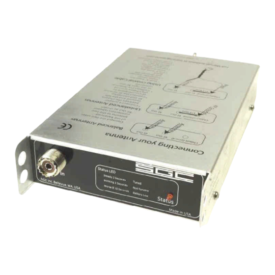
Never has there been one so easy to carry and use. And NEVER have you seen one that will tune for 5 years on a single set of AA cells! © 2004 SGC Inc. Page 5... - Page 8 Rear Panel Connections Balanced and Unbalanced Wing Nuts Indicators 1 Red LED on Front Panel: Steady for 2 seconds for tuned Blinking for 2 seconds for not tunable Morse B for 10 seconds for battery low © 2004 SGC Inc. Page 6...
-
Page 9: Mechanical Design
RF Output is from balanced and unbalanced connectors on the back. Internal construction makes the SG-211 suitable for portable or fixed location use. Corrosion- resistant hardware and passive alloys are used throughout. © 2004 SGC Inc. Page 7... -
Page 10: Sg-211 Setup
Power/SWR meter between the transceiver and the SG- 211 to monitor conditions. We recommend that you select one that measures Forward and Reverse power as well as SWR. This will provide more useful information about conditions on the line. © 2004 SGC Inc. Page 8... -
Page 11: Antenna And Rf Ground Connections
The feed line can be connected to the balanced terminals on the back of the coupler. When it is not possible to use balanced feedline, then the antenna may be connected with coax. © 2004 SGC Inc. Page 9... - Page 12 RF Out connection and the braid to the Chassis Ground with a jumper to the left RF Out connection as shown below. © 2004 SGC Inc. Page 10...
-
Page 13: Battery Replacement
SG-211 as shown below. Two Cover Screws on each side, none on front and back The batteries are in two battery holders on the SG-211 circuit board. Any suitable alkaline AA batteries may be © 2004 SGC Inc. Page 11... - Page 14 SG-211 User’s Manual used. We recommend using the highest quality alkaline AA batteries available to assure the longest life with no battery leakage that could damage the circuit board. Batteries © 2004 SGC Inc. Page 12...
-
Page 15: Antennas And The Sg-211
This keeps SWR on the feed line to an absolute minimum. 3.2 Connecting Antennas The SG-211 is provided with an SO-239 connector on the front panel for RF in. It has balanced and unbalanced connections on the back panel. © 2004 SGC Inc. Page 13... - Page 16 The balanced feed connection supports ladder line feed to a balanced antenna such as a dipole or a loop. © 2004 SGC Inc. Page 14...
-
Page 17: Balanced Vs. Unbalanced Antennas
Without a good quality ground, unbalanced antennas will cause interference, RF in the radio room, and radiate poorly. Long wires and verticals are typical unbalanced antennas. © 2004 SGC Inc. Page 15... -
Page 18: Antenna Recommendations
SG- 211. Some balanced antennas, such as the folded dipole are usually constructed with a coax feed at the center point. Simply connect your coax feed line to the SG-211 as shown. © 2004 SGC Inc. Page 16... -
Page 19: The Inverted V Antenna
The ladder line transforms the feed point impedance to something near 50 ohms at the antenna’s design frequency. Usually, the ladder line terminates in a 1:1 balun. Coaxial line from the transceiver connects to the balun. © 2004 SGC Inc. Page 17... -
Page 20: Long Wires & Inverted Ls
RF Out connector. CAUTION: Unbalanced antennas are radiating from the line as soon as they leave the SG-211. Minimize the amount of wire inside the radio room to prevent interference with electronic equipment. Minimizing © 2004 SGC Inc. Page 18... - Page 21 10% longer than the wire antenna and laid out so that it does not cross over itself or form a loop. A far better RF ground can be constructed by adding ground radials connected to the Chassis Ground connector of the SG- 211. © 2004 SGC Inc. Page 19...
-
Page 22: Vertical Antennas
239 connector or equivalent to feed the antenna. This type of antenna can be connected directly to the SG-239 or via a pigtail as shown below. Any vertical antenna fed with Coaxial cable can be connected in this way. © 2004 SGC Inc. Page 20... - Page 23 RF grounding system. Another way that a vertical can be fed is to have it fed with a wire directly from the SG-211 right-most RF hot terminal to the radiating element. To the Radiating Element © 2004 SGC Inc. Page 21...
- Page 24 Chassis ground post as shown. A properly installed antenna should not have RF power getting on the outside of the coaxial line. © 2004 SGC Inc. Page 22...
-
Page 25: Loops
It is also possible to feed a loop from a coaxial cable by connecting one side of the feed point to the center © 2004 SGC Inc. Page 23... -
Page 26: Portable Antennas
Portable whip antennas make excellent radiators and can be used in a number of configurations. Examples include fixed whip antennas like SGC’s SG-307 whip and 10 foot collapsible whips available from a number of vendors. One popular antenna uses a whip erected as a vertical antenna with radial wires extending from its base. - Page 27 1.8 to 60 Mhz. Ten foot collapsible whips will be tunable from 3.5 to 60 Mhz. Representative sources for the equipment you will need to assemble one of these portable antennas are: © 2004 SGC Inc. Page 25...
- Page 28 Tripod&Mast 6 Foot Portable Antenna Stand Tee Mount Center Tee W3FF Mount Whips SG-307 Helically Wound Whip 10 & 12 Foot Extra Long Whips Replacement Radio Shack Whips #270- 1408B AT271/A APEX Collapsible Whip © 2004 SGC Inc. Page 26...
-
Page 29: Beams
RF grounds, when required, are necessary to the operation of your antenna system. Connecting the two together can inject © 2004 SGC Inc. Page 27... - Page 30 RF Noise into your receiver and obliterate your received signal completely. Plan your antenna installation carefully! Don’t commit to a final installation until you have tried out your antennas in as near to final form as possible. © 2004 SGC Inc. Page 28...
-
Page 31: References On Antennas
SG-211 User’s Manual 3.6 References on Antennas 3.6.1 From SGC SGC, HF User’s Guide, available free from http://www.sgcworld.com/ftp/Books/hfguide.pdf SGC, Stealth Antenna Manual, available free from http://www.sgcworld.com/ftp/Books/STEALTHman.pdf SGC, Smartuners for Stealth Antennas, http://www.sgcworld.com/ftp/Books/stealth.pdf 3.6.2 Books Carr, Joseph, Practical Antenna Handbook, 3 Edition, McGraw-Hill, New York, 1998. -
Page 32: The Golden Rules Of Hf Installation
Following these rules will minimize marginal installations and problem sources such as RF feedback in the radio, power supply or cables and “hot” or RF burning microphones. If all 5 above points are followed during the © 2004 SGC Inc. Page 30... -
Page 33: Do-It-Yourself Light Bulb Test
Because different transmitters output different amounts of power, different sizes of dummy loads must be used. Dummy loads for typical amateur powers (<500 watts) are relatively inexpensive and are readily available. © 2004 SGC Inc. Page 31... - Page 34 2182 KHz). SGC recommends that you build the light-bulb dummy load with the following parts (although we have made one with an old light fixture and a makeshift version with just...
- Page 35 Key the PTT switch on the microphone and look at the light bulb. If the light bulb load is connected and the radio is transmitting, the light should turn on. Set the radio to SSB mode. © 2004 SGC Inc. Page 33...
- Page 36 The output power (light-bulb brightness) is greatest when the coupler is properly tuned. This test will ensure that the radio and coupler are working properly. © 2004 SGC Inc. Page 34...
-
Page 37: Theory Of Operation
This means that the unit can be located remotely without the inconvenience of additional wiring to provide power. For portable use, the antenna tuner draws no power from station batteries. © 2004 SGC Inc. Page 35... -
Page 38: The Matching Network
The L network transforms the impedance up to match the complex impedance of the antenna. This is a well established matching concept in military manpack applications spanning many years. © 2004 SGC Inc. Page 36... -
Page 39: The Sensor
D2 and associated circuitry detect forward and reverse power that is fed to the microprocessor A/D inputs. The microprocessor wakes up when the forward power exceeds the minimum threshold. If significant reflected power is detected, the matching sequence is initiated. © 2004 SGC Inc. Page 37... -
Page 40: The Relay Driver Matrix
With 16 relays, the circuit needs to drive 32 coils. A matrix of six columns and six rows allows selection of 36 coils with only 12 microprocessor outputs. © 2004 SGC Inc. Page 38... -
Page 41: Microprocessor
Thus, when changing frequency, the previous values are recalled, greatly speeding the matching process. U2 provides a reference to one of the A/D inputs to measure battery voltage. The processor flashes LED DS1 when a low battery condition is detected. © 2004 SGC Inc. Page 39... - Page 42 J1 provides connection to the programmer for this purpose. Since the processor is dormant except during the actual matching process, the possibility of generating RF interference in the receiver is eliminated. © 2004 SGC Inc. Page 40...
-
Page 48: Standard Warranty
This license shall be limited to using the software for contemplated operation of SGC’s product. This license does not permit any end user to (a) modify or adapt SGC’s software or to merge it into another program (b) reverse engineer, disassemble, or otherwise attempt to discover SGC’s software source code or ©... - Page 49 Cable(s) (NOTE: All couplers require RF and 12 Terminals SGC cable, 9 SGC cable, 9 feet 10 feet RG-58 SGC cable, 9 feet volt lines only. SGC cables are required for feet coaxial and coaxial and two power cable, 10 coaxial and two additional features only.)
- Page 50 Adjustable from 0-20W PEP All the Power you’ll need for base, backpack or business travel Mailing: PO Box 3526, Bellevue, WA. 98009 Shipping: 13737 SE 26 St. Bellevue, WA. 98005 Toll Free: 800-259-7331 * Phone: 425-746-6310 * Fax: 425-746-6384 www.sgcworld.com * Email: sgc@sgcworld.com...
Need help?
Do you have a question about the Smartuner SG-211 and is the answer not in the manual?
Questions and answers