Technics SA-GX550 Operating Instructions Manual
Av control stereo receiver
Hide thumbs
Also See for SA-GX550:
- Service manual (49 pages) ,
- Operating instructions manual (38 pages) ,
- Operating instructions manual (38 pages)

Related Manuals for Technics SA-GX550


Summary of Contents for Technics SA-GX550
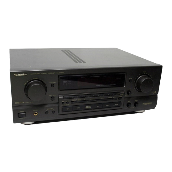
- Page 1 - Technics AV control stereo receiver SA-GX550 SA-GX350 Operating Instructions I he photoglaphs show SA-GX550. Before connecting, operating or adjusting thjs..product, read these if : ii:-_: RQT1849-P H 1292C0...
- Page 2 Please note them in the space provided below and retain Thank you for purchasing this Technics product. them for future reference. For optimum performance and safety, please read MODEL NUMBER ........
-
Page 3: Table Of Contents
Before Adjusting sound field Enjoying sound with DOLBY PRO LOGIC ..21 Suggestions for safety ......SURROUND .......... Safety ..........3 STEREO ..........Installation ..........Maintenance .......... Setting the center mode ....... Service ..........Adjusting the delay time _ ..... Adjusting the output level of each speaker .... -
Page 4: Suggestions For Safety
Belore using this unit please read these operating instructions carefully. Take special care to follow the warnings indicated the unit itself as well as the safety suggestions listed below. Afterwards keep them handy for future reference. Salty Placement 1. Ventilation -- The unit should be situated so that its Location 1. -
Page 5: Listening Caution
Please check and identify the supplied ac- cessories Listening caution power supply cord 1 pc. (For USA: SJA172-1) (For Canada: SJA172) Selecting fine audio equipment such as the unit you've just pur- chased is only the start of your musical enjoyment. Now it's time to consider how you can maximize... -
Page 6: Front Panel Controls
Control section SA-GX550 Name Re[. page Name Re[. page Power switch (POWER) (_) Muting button (MUTING) (_) Volume control (VOLUME) Tuning control (TUNING) (_) Headphone jack (PHONES) Tuning buttons (TUNING) (_) Direct tuning button (DIRECT TUNING) Tuning mode select button (TUNING MODE) _ (_) Speaker select buttons (SPEAKERS) -
Page 7: Display Section
Display section /" [TAPE MONITOR OVER i-,' ,o-:;. Nalne Name Re?. page Re[. page 2_ Remote control signal receptor Low impedance indicator i,._,_,Xt.]_o] L'S'_i_,j (_ Overload indicator (_ Speaker select indicators Tuning-mode indicators m_rn_ Band indicators 2_ Quartz lock indicator FM stereo indicator Memory indicator Input selector/frequency... -
Page 8: Equipment Connections
Connect the connection cable remote control to a This unit Technics tape deck andlor CD changer (or CD player) which (l) CONTROL REMOTE has the appropriate remote control terminal as shown at the _L._ left. If a tape deck is not being used, the CD changer... -
Page 9: Connecting Video Equipment
Connecting video equipment Stereo connection cable (not included) Monitor TV Second VCR (for playback only) (not included) (not included) Video connection cables not included) VIDEO AUDIO VIDEO o4,0 @ "--IMONITOR ACOUTLETS VCR2 IN I OUT VCR1 Cooling fan The cooling fan operates at high power output levels only. -
Page 10: Antenna Connections
outdoor antenna t.ot included) indoor antenna ti.cl.aed) The outdoor antenna should be used when using the main unit in This antenna is normally sufficient for reception of FM broad- mountainous areas or in spaces enclosed by reinforced concrete casts. where FM indoor antenna (included) -
Page 11: Am Loop Antenna
loop antenna _i.cl.aea) outdoor antenna _.ot i.ciudea) This antenna is normally sufficient for reception ol AM broad- The outdoor antenna should be used when using the main unit in casts. mountainous areas or in spaces enclosed by reinforced concrete where the AM loop antenna (included) does not provide satisfac- tory reception. -
Page 12: Speaker Connections
Connection of front speakers Placement of speakers Right speaker Left speaker As well as enjoying normal stereo reproduction with both the left and right front speakers connected, a center speaker and rear (not included) (not included) speakers can also be connected to the main unit in order to enjoy playback with a feeling of presence... -
Page 13: Connection Of Rear Speakers
Connection of rear speakers Connection of center speaker Center speaker Right speaker Left speaker (not included) (not included) not included) Sound will only come out when the SUR- ROUND mode or 3 STEREO mode of the Dolby Pro-Logic System is on. This unit This unit _cluded) -
Page 14: Basic Operations
POWER VOLUME TAPE/DCC Belore operation, set VOLUME to the "0" position..... POWE..Press PO WER tO Switch 0n ....Press to seiect the desired source. VCR 1: To watch video tapes (VCR 1) the power. TAPE/DCC- To listen to tape or digital VCR 2"... -
Page 15: To Listen To A Desired Audio Source While Watching Video Picture
BALANCE OMUTING © VOLUME _PLAKLHS 'L'_..:T_u.K LOUDNESS BASS TREBLE Headphones (not included) F---I © © Plug type: 1/4 inch phone plug stereo type To listen to a desired audio source To emphasize low-frequency sound while watching video picture Press LOUDNESS. 1. -
Page 16: Listening To Radio Broadcasts
Direct access tuning Specify the frequency using the numeric buttons to directly tune to the desired broadcast station. m:T_ © ..........• MANUAL LOCK ..S_EAKE_ L" L...J L...I I..!. Press TUNER ..1 r ..BAND .... Press BAN D tO select "FM "... -
Page 17: Sequential Tuning
Sequential tuning If the frequency is not known, use the tuning control for sear- ching. Manual tuning Auto tuning The frequency will change only by the amount that the tuning con- This automatically searches for broadcast stations which provide trol is turned. strong signal reception. -
Page 18: Sequential Tuning
Preset tuning Sequential tuning By presetting the desired broadcast stations into the memory If the frequency is not known, use the tuning buttons for sear- ching. channels of this unit, broadcast stations can be selected simply by pressing numeric button(s). (Refer to page 20 for tuning.) -Before presetting How many broadcast stations can be preset? - Page 19 Automatic memory presetting Manual memory presetting ©:!: .."_ Pres,, : ru,E,: ....TUNERI ....' Press BAND Press BAND to select "FM" ... B:','ND ..Press BANDto select ,FM,, or "AM". or "AM"....Set t0 thedesired br0ad....Settothe frequencY from...
- Page 20 Preset tuning _co...ued_ To listen to preset broadcast stations @ oo " _' "Press :FUNERI ....specify the preset channel /.__J using the numeric button(s). (Example: Channel 12) ,_i2j (Within 2 sec.) MANUAL LOCK ..SPEAKE"S /..i L.. / / i\.!./ =,.Au'ro _Oj/...
-
Page 21: Enjoying Sound With Dolby Pro Logic
By combining front (A or B), center and rear speakers, SUR- Setting center mode ROUND mode which conveys a feeling of presence or 3 STEREO mode which conveys a feeling of orientation can be enjoyed. For Dolby Pro-Logic systems, center mode setting is necessary to play back bass sounds effectively. -
Page 22: Adjusting The Delay Time
Adjusting delay time Adjusting output level of each speaker lVlVh [q imqll ,_,l,_l_ -,v,vnI i'lk1.ll "! :[O]U _I iii]n In order to reproduce the feeling of movement of the sound and clear orientation of sound, it is important to correctly adjust the Adjust so that sound... -
Page 23: Enjoying With Surround Or 3 Stereo
Enjoying with SURROUND 3 STEREO { 6")i ..V0LUME ..TUrn VoLuME t0 set _Jt._ ///'_'_'_ volume level normally used for enjoying the source. CENTER LEVEL Press CENTER LEVEL (-) (+) to adjust the output level or REAR LEVEL (-) balance. -
Page 24: Making A Recording
Tape recording on the tape deck or digital compact cassette (DCC) Before recording, prepare the tape deck or DCC for recording (recording level adjustment, etc.). See the tape deck's or DCC's operating instructions for details. TAPEIDCC_ '°'"""°'-'- '_'_--_" _ I _1_ I .. -
Page 25: Recording From Vcr 2 To Vcr 1
Recording £rom VCR 2 to VCR 1 (VCR 1)recording from audio source Before recording, prepare the VCR (VCR 1)for recording (recor- ding level adjustment, etc.). Before recording, prepare the VCR (VCR1) for recording (recor- See the VCR's operating instructions for details. ding level adjustment, input selector setting, etc.). -
Page 26: To Record Picture From Vcr 2 And Sound From A Different Audio Source
Do not attempt to remove the cover(s) or repair the unit yoursell. To record picture from 2 and Refer servicing to qualified personnel only. sound from a different audio source Product information Before recording, prepare the VCR (VCR 1) for recording (recor- ding level adjustment, input selector setting, etc.). -
Page 27: Troubleshooting Guide
(enclosed with this unit) checks or a minor adjustment on your part may eliminate the pro- to locate a convenient service center, or consult your Technics blem and restore proper operation. dealer for instructions. (In U.S.A. consult MSC Authorized Servicenters for detailed instruc- tions.) - Page 28 • AMPLIFIER SECTION • FM TUNER SECTION Rated minimum sine wave Frequency range 81.9 - 107.9 MHz Sensitivity 11.2 dBf (2 pV, iHF '58) RMS power output 50 dB quieting sensitivity 20 Hz-20 kHz both channels driven MONO 18.3 dBf (4.5 _V, IHF '58) 0.05% total harmonic...
Need help?
Do you have a question about the SA-GX550 and is the answer not in the manual?
Questions and answers