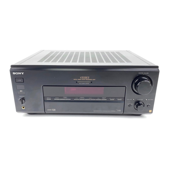
Sony STR-V333ES Operating Instructions Manual
Fm stereo fm-am receiver
Hide thumbs
Also See for STR-V333ES:
- Service manual (104 pages) ,
- Dimensional drawing (1 page) ,
- Operating instructions manual (68 pages)

Related Manuals for Sony STR-V333ES


Summary of Contents for Sony STR-V333ES
- Page 1 ON"_ 4-230-072-12t1 FM Stereo FM.AM Receiver Operating Instructions STR-V444ES STR-V333ES ,:_, 2 000 Sony Corporation...
- Page 2 INFORMATION ENERGY STAR' is a U.S. registered mark. adequate ventilation to prevent heat As an ENERGY STAR" partner; Sony This equipment has been tested and found to htfildup and prolong the life of the Corporation has determined that this comply with the limits for a Class B digital receiver.
-
Page 3: Table Of Contents
TABLE OF CONTENTS About This Manual The instructions in this inanual are R)r models STR V444ES and STR V333ES. Check your model number Hooking Up the Components by looking at the lower right corner of the fi'ont panel. Unpacking this manual, tile STR-V444ES is used for illustration Antenna Hookups... -
Page 4: Unpacking
Unpacking Check that you received the fffllowing items with the unit: FM wire antenna AM loop antenna Audio/video/control S connecting cord (1) Control S connecting cord (1) Remote coimnander RM-LJ304 (reinote) R6 (size AA) batteries STR V444ES only • Remote commander RM-US104 (remote) (1) •... -
Page 5: Antenna Hookups
Antenna Hookups AM loop antenna (supplied) "0 FM wire antenna (supplied) --@@@@- IMPEDANCE USE 4-16_ -@ @ EN_TERIIr REAR CENTER REAR • To prevent noise pickup, keet) the AM loop antenna Connect the To the away from the receiver and other components. AM loop antenna AM terminals •... -
Page 6: Hookups
Audio Component Hookups "T- Audio cords (not supplied) deck MDIDAT _Vhen connecting a cord, be sure to match the color coded pins the appropriate jacks Oil tile components. "o White (L) White (L) ¢ Red (R) Red (R) Turntable "o Tape deck CD player Connect... -
Page 7: Hookups
Video Component Hookups ¸¸¸¸¸ Audio/video cords (not supplied) When connecting a cord, be sine to match the color coded pins to tile appropriate jacks oil the components. Yellow (video) Yellow (video) "a White (L/audio) White (L/audio) TV or satellite tuner DVD or LD player Red (R/audio) Red (R/audio) - Page 8 RF OUT jack via an RF dem@dulato_; like Audio/video cords (not supplied) the Sony MOD RFI (not supplied). When connecting a cord, be sure to match the color coded pins to the appropriate jacks on the components.
- Page 9 Connect the digital otJtput jacks of your MD or DAT deck to the receiver's digital input jack and connect the digital Optical digital cords (not supplied) input jacks of your MD or DAT deck to the receiver's digital output jack. These connections allow you to make Black Black...
- Page 10 5.1CH Input Hookups Although this receiver incorporates a nmlti channel decodel, it is also equipped with 5.1CH INPUT jacks. Audio cords (not supplied) These connections allow to enjoy imfltichannel %vo for the 5.1CH INPUT FRONT and REAR jacks software encoded in f_rTnats other than...
-
Page 11: Other Hookups
Other Hookups "o Red (R) Red (R) Audio/video/control S connecting cord (1) "a Yellow (video) O _\ Yellow (video) White (L/audio) _) _--_\_/_:_mZ_ White (L/audio) 0 ¢D Red (R/audio) Red (R/audio) Black (control S) 0 _ Black (control S) (_ Control S connecting cord(1) Black_ ._z,... - Page 12 TV. the receiver while MD Editor" operate using the "Sony soflwm e. This may cause a malt\ruction. • If you have a Sony CD changer with a COMMAND MODE selector If' your CD changer's COMMAND MODE selector can be set to CD 1, CD 2, or CD 3, be sure to set the comi-nand i'node to "CD 1"...
- Page 13 Before connecting the AC power cord of this receiver to a wall outlet: • Connect the speaker systeln to the receiver (see page 15). €- "o • Turn tile MASTER VOLUME control to tile leftmost position (0). Ccmnect the AC power cord(s) of your audio/video "o components to a wall outlet.
- Page 14 Cursor buttons © Jog dial SET UP SET UP button: Press to enter the setup mode when specifying speaker types and distances. Cursor buttons (_I_): Use to select paralneters after pressing the SET UP button. Jog dial: Use to adjust the setting of each parameter.
-
Page 15: Speaker System
Speaker System Hookup This receiver corresponds with 6. l channel decording. yOU do not place a center speaker, you can place a rear center speaker. For details, see page 18. Front speaker (R) Front speaker (L) Speaker cords (not supplied) One fbr each fiont, rear, and center speaker (-) _ Monaural audio cord (not supplied) -
Page 16: Speaker System Hookup
Speaker System Hookup Short circuiting of the speakers inay damage the receiver. To enjoy inulti channel surrotn-ld, connect front, center, To prevent this, make sure to take the following and rear speakers with a nominal impedance of 8 ohms or highei, and set the speaker IMPEDANCE SELECTOR to... - Page 17 Performing Initial Setup Operations Once you have hooked up the speakers and turned on the power, clear the receiver's memm_. Then specif,/the Beff_re using your receiver fbr the first time, use the SET speaker parameters (size, position, etc.) and perfbml UP button to adjust the setup parameters so that they other initial setup operations...
-
Page 18: Surround Setup
Multi Channel Surround Setup "_"_When setting upthe rear center speaker For the best possible surround sound all speakers should Set the speaker at least one meter bebind the listening position. It be the same distance the listening position (O). is recommended to place the speaker at an equal distance from However, this unit lets you... - Page 19 • Rear center speaker size (REAR CTR)* • Center speaker size (CENTER) Initial Initial setting : LARGE setting This parameter ean be set when the eenter speaker is set to • ffyou eonneet a large speaker that will eftbctively "NO" and the rear speakers are set to "LARGE" or reproduce bass frequencies, select "LARGE".
- Page 20 Multi Channel Surround Setup • Sub woofer selection (SUB WOOFER) • Rear center speaker distance (REAR CTR) Initial setting : YES Initial setting : 11%et (3.5 meter) • If you connect a sub woot_r, select "YES". Set the distance from your listening position to the rear •...
- Page 21 • Rear L/R speaker position (REAR L/R PLACE)* • Rear L/R speaker height (REAR L/R HGT.)* Initial setting : BEHIND Initial setting : LOW This parameter lets you speeifk/tile location of your rear This parameter lets you speeii_y the height of your rear L/R speakers fbr proper implementation of tile Digital...
- Page 22 Multi Channel Surround Setup • Front speaker crossover frequency (FRONT SP >) Use the remote while seated in your listening position Initial setting : ST[) (=120 Hz) adjust tile volume of each speaker. Lets you adjust the fi'ont speaker bass crossover frequency when tile ti'ont speakers are set to "SMALL".
-
Page 23: Before You Use Your Receiver
Before You Use Your Receiver There is no sound no matter which component selected. Make sure that you have: Check that both the receiver and all components • Turned MASTER VOLUME to the M'tmost position (0). are turned • Selected tile appropriate front speakers (see "[] Check that the MASTER VOLUME control is not SPEAKERS selector"... -
Page 24: Parts Description
Front Panel Parts Description [] I/_ switch Press to turn the receiver on and off. • Befiore turn on the receiver, make sure that have turned MASTER VOLUME control to the lef_most position to avoid damaging your speakers. MASTER VOLUME control After turning on the component you selected, rotate to... - Page 25 MASTER SOLUME r--q MU_rl C H_NELDEC_O_G r---1 SP_KE_, I" Ai,D_ S_ITI PHONES "111 "1 FUNCTION control AUDIO SPLIT button Rotate to select the component you want to use. Press to assign the audio input for each flmction. This flmction is convenient when you are using a To select Rotate to light...
- Page 26 Front Panel Parts Description M_STER _OLUME __':_ ..II10 ii(/ ))/ 0 _HONES "o "R ¢0 IR receptor Use these buttons to enjoy surround sound. "R Receives IR signals emitted by the [ei-llote. details, see "Enjoying Surround Sound" starting from "o page 29.
- Page 27 Set the automatic application of the sound field to a program source (page 52). Auto Ftlnrtion Sperify whether or not Sony romponents connected via control A1 cords will tmn on o1"offwhen selected using the function buttons (page 52). 2 Way Remote Turn on or off"response to remote signals...
- Page 28 Front Panel Parts Description SLEEP button Jog dial Press to activate the sleep timer. Turn to adjust the selected speaker level, surround, and equalizer parameters (etc.). DIMMER button LEVEL button Press repeatedly to adjust tire brightness of the display. Press to activate the speaker level parameters (page [] TUNING +/- buttons...
- Page 29 The virtual sound modes contain compelling applications of tile Sony Digital Cinema Sound digital signal processing technolog_ They shift tile sound away fi'om tile actual speaker locations to simulate tile presence several "virtual"...
- Page 30 Selecting a Sound Field MODE +/- ANALOG DIRECT CINEMA STUDIO EX. I 2CH ICursor buttons You can enjoy surrormd sound simply by selecting one of tire pre programmed sound fields according to the program want to listen Press MODE repeatedly to select the sound field...
- Page 31 Software with 2 channel audio signals, is decoded with Dolby Pro Logic to create surround eftects. CINEMA STUDIO EX. A I/2/ Reproduces the sound characteristics of tile Sony Pictures This is a standard mode, great fior (Press CINEMA STUDIO EX Entertainment "Ca W Grant Theater"...
- Page 32 Selecting a Sound Field Notes Sound field Effect MULTI DIMENSION Uses 3D sound imaging to create an array of virtual rear (Vh tual Multi Dimension) speakers positioned higher than tile listener fl'om a SIDE* i:!:_;i?, single pair of actual rear speakers. This mode creates sets of virtual speakers surrounding...
- Page 33 Sound field Effect Notes VIRTUAL ENHANCED A 1) Uses 3D sound imaging to rreate 3 sets ofvirtnal rear (Virtnal Enhanced Snrrotmd A) speakers from tile sound of the flont speakers withont :::: :::: :::: nsing actual rear speakers. Q )" ':,]:, VIRTUAL ENHANCED B1/ Uses 3D sound imaging to create 1 set of virtual rear...
-
Page 34: Sound Field
Selecting a Sound Field Use the buttons on the front panel to operate following modes AUTO FORMAT DECODING Automatically detects tbe type of audio signal being You can use this mode as a reference. (Press the A.ED. button) input (Dolby Digital, DTS, Dolby Pro Logic,... -
Page 35: Operations
Understanding the Multi-Channel Surround Displays [] PRO LOGIC [] Playback channel indicators The letters light to indicate the channels being played Lights when this unit applies Pro Logic processing back. two channel signals in order to output the center and L: Front Left R: Front Right surround... -
Page 36: Sound Fields
Customizing Sound Fields 6.1ch Matrix (6.1 MATRIX) By adjusting the surround paraineters Initial setting : AUTO equalization of the front, rear and center speakers, This parameter can be used when NORMAL SURROUND can customize the sound fields to suit your particular is selected. - Page 37 Reverberation time (REVERB) Bass adjustment (Gain/Frequency) Unlike the equalizer in the equalizer menu (which allows Initial setting : midpoint Before sound reaches our ears, it is reflected you to individually adjust the overall sound quality of each set of speakers) these parameters allow you to (reverberated) i-flany times between he left and right...
-
Page 38: Customizing Sound Fields
Customizing Sound Fields Rear L/R level (REAR L/R) hfitial setting : 0 dB The LEVEL inenu contains parameters that let you adjust Lets you adjust level of the rear (left and right) speakers. the balance and speaker vohnnes of each speaker. The level can even be adjusted during 5.1 CH input. - Page 39 dts LFE (Low Frequency Effect) mix level Initial setting : 0 dB The EQ nlenu lets you adjust tile equalization (bass, mid, This paralneter lets you attenuate the level of the LFE and treble fl'equencies) of the front, center, rear L/R and (Low Frequency Eftect) channel output fl'om the sub...
- Page 40 Customizing Sound Fields Front speaker treble adjustment (Gain/ Rear L/R speaker midrange bandwidth Frequency) This parammeter lets you adjust tile width of the Adjust as described in "Front speaker bass adjustment". midrange band. • Tile gain call be adjusted _+10dB in 1 dB steps. •...
- Page 41 < SURROUND > 6.1 PRO EFFECT W ALLREVERB FRONTSCREEN VIRTUAL REAR BASS BASS MID MID TREBLE TREBLE MATRIX LOGICLEVELTYPE TIME REVERB DEPTHSPEAKER ENHANCER GAIN FREQ GAIN FREQ SLOPEGAIN FREQ AI ITO FORMAT DECODING ANALOG DIRECT NORMAL SURROUND • • • •...
- Page 42 Customizing Sound Fields < LEVEL > FRONT REAR CENTER REAR LIR REAR WOOFER tits L FE DRANGE BALANCEBALANCE LEVEL LEVEL CENTER LEVEL MIX_ COMP_ • • • • • • • • • • • • AIITO FORMAT DECODING ANALOG DIRECT •...
- Page 43 ii iiii i i i iiiiiiiiiiii aii iaii!ii!ii!ii!i iii iiiiiai! < EQUALIZER (BANK) > < FRONT > < CENTER > B.GAINB.FREQ M.GAIN M.FREQ M,SLOPE T .GAIN T.FREQ B.GAIN B.FREQM.GAINM.FREQM,SLOPE T .GAIN T.FREQ • • • • • • AIITO FORMAT DECODING •...
- Page 44 Customizing Sound Fields < EQUALIZER (BANK) > < REAR L/R > < REAR CENTER > B.GAINB.FREQM.GAINM.FREQM,SLOPE T .GAIN T.FREQ B.GAIN B.FREQ M.GAINM.FREQM,SLOPE T .GAIN T.FREQ AIITO FORMAT DECODING • • • • • • • ANALOG DIRECT NORMAL SURROUND • •...
-
Page 45: Direct Tuning
You can ume in stations on this receiver in the following ways: Direct Tuning You can enter a frequency of the station you want directly by using the numeric buttons on the supplied remote (see page 46). Automatic Tuning If you don't know the fl'equency of the station you want, you can let the receiver scan all available stations... -
Page 46: Tuning
Direct Tuning PRESET TUNING +/- DISPLAY FM/AM TUNING +/- °1 Use the supplied remote to perforln tile following operations. For details on tile buttons used in this section, see tile operating instructions for tile sut)plied remote. Rotate FUNCTION to select the tuner. - Page 47 Automatic Tuning Preset Tuning For details on the buttons used in this section, see "Brief For details on the buttons used in this section, see "Brief descriptions of buttons used to receive broadcasts" descriptions of buttons used to receive broadcasts" page 46.
- Page 48 Preset Tuning You can tune the preset stations either of the fkfllowing two ways. Scanning the preset stations Rotate FUNCTION to select the tuner. The last received station is tuned Press PRESET TUNING + or PRESET TUNING repeatedly to select the preset station you want.
- Page 49 Cursor buttons SET UP @T @ SLEEPNAME ENTER FUNCTION Jog dial NAME button: Press to naine preset stations or program sources. Jo 9 dial: Use to select characters when naming preset stations or program sources. Cursor buttons (_/_): Use to move the cursor when naming preset stations or program...
-
Page 50: Recording
Naming Preset Stations Recording Program Sources You can enter a name of up to 8 characters f_)r preset Your receiver makes it easy to record to and fi'om the statioi-is and program sources. These names (for example, components connected to it. You don't [lave to connect "VHS") appear in the receiver's display... -
Page 51: Using The Sleep Timer
Using the Sleep Timer You can set the receiver to turn off automatically at a specified time. You can record fl'om a VCR, a TV. or an LD player using the t_ceiver. You can also add audio f'roi'fl a variety Press SLEEP on the front panel or on the remote... -
Page 52: Using The Set Up Button
Turn thejog dial to select "AUTO OFF" or "ALWAYS Turn the jog dial to select "ON" or "OFF". ON". Turning on the CONTROL A1 II auto fimction parameter lets you turn Sony components connected via CONTROL A1 cords (see page 12) on automatically when you press the corresponding t_mction button. - Page 53 2 way only). remote control system, be sure to periorm the following • When you want to use 2 Sony receivers in the same operation to limit response to signals sent fi'om the remote rooi'fl with the remote.
-
Page 54: Control System
A1 ii which is the standard system in the SONY particular connections or setup options, refer to tile 300 disc CD changer and other recent Sony components. Operating Instructions supplied with tile component(s). Components with CONTROL A1 jacks are compatible... - Page 55 Operating Instructions supplied with the recorder component. Automatic function selection When connect a CONTROL A lII compatible Sony amplifier (or receiver) to other Sony components using monaural mini plug cords, the fimction selector on the...
-
Page 56: Troubleshooting
Also, see "Checking connections" on page 23 to verif_y that the connections correct. Should any problem persist, consult your neaiest Sony dealer. There's no sound or only a very low-level sound is heard. Check that the speakers and components connected securely. - Page 57 No sound is heard from the center speaker. No picture or an unclear picture appears on the TV screen or monitor. -_ Make sure the sound fieM flmction is on (press MODE +/ ). Select the appropriate f\metion on tile reeeiver. •"_ Select a sound field containing tile word "cinema"...
-
Page 58: Specifications
Specifications Frequency response Inputs (Digital) PHONO: RIAA DVD/LD IN, CD IN equalization curve (STR V444ES) POWER OUTPUT AND _+0.5dB (Coaxial): TOTAL HARMONIC CD, TAPE, MD/DAT, Sensitivity: DISTORTION: DVD/LD, TV/SAT, hnpedance: 75 ohins S/N: 100 dB VIDEO 1, 2, and With 8 ohm loads, both VIDEO 3: (A, 20 kHz LPF) channels driven, from... - Page 59 Tuning range 87.5 108.0 MHz Tuning range With 10 kHz tuning Inputs Video: 1 Vp p 75 ohms scale: S video: 1710kHz 4) Antenna terminals Y: 1 Vp p 75 ohms 75 ohlns, unbalanced With 9-kHz tuning C: 0.286 Vp-p scale: 75 ohms 1710kHz 4)
- Page 60 Specifications Tuner section: System PLL quartz locked digital synthesizer systeln Preatnplifier section: Low-noise NF type equalizer Power amplifier section: Puie-colnplementary SEPP Power requirements 120 V AC, 60 Hz Power consumption STR-V444ES 420 W STR V333ES 410W AC outlets 2 switched, total 120 W/1A 430 ×...
-
Page 61: Glossary
Level Early signal processing technology reflections Reverberation developed by Sony. Unlike previous surround sound fields mainly directed at tile reproduction of illusic, Digital Cinema Sound is designed specifically for the enjoyment inovies. Time... - Page 62 Tables of Settings Using SURROUND, LEVEL, EQ, and SET UP buttons You can make various settings using the LEVEL, SURROUND, EQ, SET UP buttons, jog dial, and cursor buttons. The tables below show each of the settings that these buttons can make.
- Page 63 Press and light Press <_ or _ to select Turn jog dial to select See page EQ button FRONT BASS XXX dB between -10 dB to +10 dB (in 1 dB steps) FRONT BASS XXX Hz between 99 Hz and 1.0 kHz (in 21 steps) FRONT MID XXX dB between -10 dB to +10 dB ()n 1 dB steps)
-
Page 64: Set Up Buttons
Tables of Settings Using SURROUND, LEVEL, EQ, and SET UP buttons Press Press < or > to select Turn jog dial to select See page SET UP button FRONT IXXXXXX] LARGE, SMALL CENTER IXXXXXXI LARGE, SMALL, NO REAR L/R IXXXXXX] LARGE, SMALL, NO REAR CTR IXXXXXX] LARGE, SMALL, NO... -
Page 65: Index
Index AC 3. See Dolby DigJtal (AC 3) Hookups Scanning Adjusting 5.1 CH input preset stations. See Preset brightness of the display AC power cord tm?i*g antennas radio stations. See Automatic equalizer speaker volumes audio components tm_ing surround parameters digital coinponents 8, 9 Selecting... - Page 66 Sony Corporation Printed in MaIaysia...