Table of Contents
Advertisement
STR-V5550/V7770
SERVICE MANUAL
This set is the tuner and amplifier
section in MHC-V5550/V7770AV.
Amplifier section
The following measured at AC 230V 50/60 Hz
DIN power output (Rated) (FRONT)
95 + 95W (6 Ω at 1kHz DIN)
Continuous RMS power output (Reference)
FRONT SPEAKER: 110 + 110W
(6 Ω at 1kHz, 10% THD)
CENTER SPEAKER: 55W
(8 Ω at 1kHz, 10% THD) (V7770)
REAR SPEAKER: 35 + 35W
(8 Ω at 1kHz, 10% THD) (V7770)
The following measured at AC 120, 220, 240V 50/60Hz
DIN power output (Rated) (FRONT)
100 + 100W (6 Ω at 1kHz DIN)
Continuous RMS power output (Reference)
FRONT SPEAKER: 120 + 120 W
(6 Ω at 1kHz, 10% THD)
CENTER SPEAKER: 60W
(8 Ω at 1kHz, 10% THD) (V7770)
REAR SPEAKER: 40 + 40W
(8 Ω at 1kHz 10% THD) (V7770)
Peak music power output 2400W (V7770)
2000W (V5550)
Inputs
MD/VIDEO 1 IN (phone jacks): voltage
450/250mV, impedance 47kΩ
AV INPUT AUDIO (phone jacks): voltage
250mV, impedance 47kΩ
MIX MIC 1/2 (phone jack): sensitivity 1mV,
impedance 10kΩ
Output
MD/VIDEO 1 OUT (phono jacks): voltage
450/250mV, impedance 1kΩ
PHONES (stereo phone jack): accepts
headphones of 8Ω or more.
FRONT SPEAKER:
accepts impedance of 6 to 16Ω
CENTER SPEAKER:
accepts impedance of 8 to 16Ω (V7770)
REAR SPEAKER:
accepts impedance of 8 to 16Ω
SUPER WOOFER:
Voltage 1V, impedance 1kΩ
MICROFILM
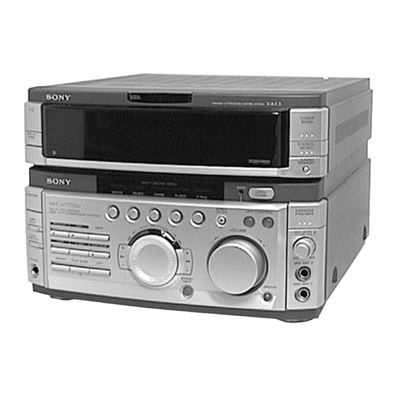
Photo : STR-V7770
SPECIFICATIONS
Tuner section
FM stereo, FM/AM superheterodyne tuner
FM tuner section
Tuning range
Aerial
Aerial terminals
Intermediate frequency
AM tuner section
Tuning range
Thai models:
Other models:
Intermediate frequency
Antenna
General
Power requirements
Chinese, Thai models:
Other models:
Power consumption
Dimensions (w/h/d)
Mass
Design and specifications are subject to change without notice.
FM STEREO/FM-AM RECEIVER
E Model
Chinese Model
87.5 – 108.0MHz
FM lead aerial
75Ω unbalanced
10.7MHz
531 – 1,602kHz (with the AM tuning
interval set at 9kHz)
530 – 1,710kHz (with the AM tuning
interval set at 10kHz)
MW: 531 – 1,602kHz (with the MW tuning
interval set at 9kHz)
530 – 1,710kHz (with the MW tuning
interval set at 10kHz)
SW: 5.95 – 17.90MHz (with the SW tuning
interval set at 5kHz)
450kHz
AM loop antenna External antenna terminal
220V AC, 50/60Hz
120V or 220V or 230 – 240, 50/60Hz
Adjustable with voltage selector
300W
Approx. 288 × 205 × 375mm
Approx. 8.8kg
Advertisement
Table of Contents


Need help?
Do you have a question about the STR-V7770 and is the answer not in the manual?
Questions and answers