
Related Manuals for Universal Audio 6176


Summary of Contents for Universal Audio 6176
- Page 1 Model 6176 Channel Strip Universal Audio Part Number 65-00053 Universal Audio, Inc. Customer Service & Tech Support: 1-877-MY-AUDIO Business, Sales & Marketing: 1-866-440-1176 www.uaudio.com...
-
Page 2: Notice
6176, 1176LN, 2-1176, LA-610, LA-2A, 2-LA-2, LA-3A, 2-610, 710, 4110, 8110, SOLO/110, SOLO/610, 2192, DCS Remote Preamp, UAD and the Universal Audio, Inc. logo are trademarks of Universal Audio, Inc. Other company and product names mentioned herein are trademarks of their respective... -
Page 3: A Letter From Bill Putnam, Jr
Developing the 6176 —as well as Universal Audio’s entire line of quality audio products designed to meet the needs of the modern recording studio while retaining the character of classic vintage equipment—has been a very special experience for me and for all who have been involved. -
Page 4: Important Safety Instructions
Important Safety Instructions _____________________________________________________________ Before using this unit, be sure to carefully read the applicable items of these operating instructions and the safety suggestions. Afterwards, keep them handy for future reference. Take special care to follow the warnings indicated on the unit, as well as in the operating instructions. -
Page 5: Table Of Contents
Table of Contents _____________________________________________________________ Notice ...........................ii A Letter From Bill Putnam, Jr....................iii Important Safety Instructions ....................iv Two Page, Two Minute Guide To Getting Started ................. 1 Front Panel ..........................3 Rear Panel ..........................9 Interconnections ........................10 Insider’s Secrets ........................11 The Technical Stuff ....................... -
Page 6: Two Page, Two Minute Guide To Getting Started
It will tell you everything you need to know to get your Universal Audio 6176 up and running, without bogging you down with details. Of course, even the most expert of us has to crack a manual every once in awhile. As the saying goes, “as a last resort, read the instructions.”... - Page 7 The Two Page, Two Minute Guide To Getting Started _____________________________________________________________ Step 8: On the right side of the front panel, set the Ratio switch to BP (fully counterclockwise) in order to temporarily bypass the 6176 limiter / compressor section. Set the Meter switch to PRE so that the meter displays the output level of the signal leaving the 6176 preamp section.
-
Page 8: Front Panel
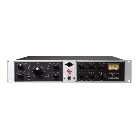
Front Panel _____________________________________________________________ NOTE: The left side of the 6176 front panel contains all preamp controls, while the right side contains all limiter / compressor controls. All controls (except the Level, Attack, Release, Input, and Output knobs) are stepped, allowing settings to be easily reproduced. (1) Gain - Adjusts the gain of the input stage in 5 dB increments. - Page 9 Front Panel _____________________________________________________________ Hi-Z - Selects the input signal arriving at the front panel unbalanced ¼" jack Hi-Z connection. ( see #5 on page 4) Intended for the direct connection of electric guitar, electric bass, or any instrument with a magnetic or acoustic transducer pickup, this can be set to either 47K ohms or 2.2M ohms.
- Page 10 Front Panel _____________________________________________________________ (8) High Boost/Cut - Selects the amount of cut or boost applied by the high shelving filter. The positive and negative numbers on the front panel denote dB values (-9, -6, -4.5, -3, -1.5, 0, +1.5, +3, +4.5, +6, +9).
- Page 11 Front Panel _____________________________________________________________ (14) Attack - Sets the amount of time it takes the limiter /compressor to respond to an incoming signal and begin gain reduction. The 6176 attack time is adjustable from 20 microseconds (FAST) to 800 microseconds (SLOW). The attack time is fastest when the Attack knob is in its fully clockwise position, and is slowest when it is in its fully counterclockwise position.
- Page 12 Front Panel _____________________________________________________________ (18) Output - Determines the final output level of signal leaving the limiter / compressor section. Once the desired amount of limiting or compression is achieved with the use of the Input control, the Output control can be used to make up any gain lost due to gain reduction. Set the Meter switch to the Compressor (COMP) position while using the Output knob to set the desired output level.
- Page 13 Front Panel _____________________________________________________________ Setting the 6176 to a ratio of ALL causes distortion to increase radically due to a lag time on the attack of initial transients and constant changes in the attack and release times as well as a change in the bias points. Consequently, the meter will go wild, often resting at maximum.
-
Page 14: Rear Panel
Rear Panel _____________________________________________________________ (1) Limiter / Compressor LINE OUTPUT A balanced XLR connector carrying the line-level output signal of the 6176 limiter/compressor section. Pin 2 is wired positive (hot). (2) Limiter / Compressor LINE INPUT Connect line-level input signal (coming from a device such as a mixer, DAW, tape machine, or signal processor) to the limiter/compressor section via this balanced XLR connector. -
Page 15: Interconnections
Interconnections _____________________________________________________________ When operating in JOIN mode, the rear panel Preamp LINE OUT and the Limiter/Compressor LINE IN jacks are automatically disconnected. For most applications, we recommend keeping the 6176 preamp Level control set between 7 and 10. Adjustments can then be made to the preamp Gain, Impedance, and Filter controls, as well as the various limiter/compressor controls, to achieve the optimum sound for your signal source. -
Page 16: Insider's Secrets
1176LN or an LA-2A (another vintage compressor, now manufactured by Universal Audio, available as a standalone unit or in combination with a channel of the 2-610 preamp, in our LA-610 model), depending on the tone they want, not necessarily on how they differ as compressors. - Page 17 1176s. I couldn’t part with them for anything. They sound fabulous.” Added reviewer Hugh Robjohns, writing about the Universal Audio 1176LN reissue in Sound on Sound magazine in June, 2001: “The 1176LN is judged by many to be unsurpassed as a vocal compressor, and I would certainly agree that it can be extremely effective.
- Page 18 Insider’s Secrets _____________________________________________________________ things up; maybe a little bottom end gets squeezed out or maybe they are just sort of excitingly solid state... The big thing for me is the clarity, and the improvement in the top end.” Last but not least, if you’re trying to get an extra dose of attitude in a lead vocal, try ALL mode with short attack and release times.
- Page 19 Insider’s Secrets _____________________________________________________________ Remember, the limiter/compressor section in the 6176 is program-dependent. That’s an important feature that allows it to be used in a musical, percussive way. Let’s say you have a medium tempo, 4/4 rock beat—an excellent scenario for using ALL mode. In this application, you’d probably have a lot of input level, a slowish attack (so that the transients sneak through), and a quick release.
- Page 20 Insider’s Secrets _____________________________________________________________ “Treating some electric guitar sounds that had been previously recorded,” Curwin added, “allowed the opportunity of experimenting with the different ratios and the attack and release controls, and with careful positioning it was possible to give the guitar a lot of punch and an apparent sense of urgency in the mix.”...
- Page 21 Insider’s Secrets _____________________________________________________________ Versatility Of course, no preamp or compressor, no matter how well designed, is perfect for all applications or for all microphones. Fortunately, the 6176 is designed to work with a wide variety of microphones and signal sources, and we think you’ll find that it acts as the perfect sonic complement for most of them.
- Page 22 Insider’s Secrets _____________________________________________________________ Mixing Applications The line-level input of the the 6176 allows it to be used in mixing as well as tracking. Even if no equalization is used, and even if the limiter/compressor section is set to Bypass, the signal continues to pass through the transformers, the tubes, and the polarity-reverse circuits, making it extremely useful for coloration of tracks.
-
Page 23: The Technical Stuff
The Technical Stuff _____________________________________________________________ History of the 6176 Preamp section The lineage of the 6176 can be traced back to two devices long revered by audio engineers the world over: the 610 preamplifier and the 1176LN limiting amplifier. The preamp section of the 6176 was inspired by the 610 console built by Bill Putnam Sr. in 1960 for his United Recording facility in Hollywood. - Page 24 Designed by Bill Putnam Sr., original founder of Universal Audio, its circuit evolved from the popular 175 and 176 vacuum tube limiters, combined with the latest solid-state amplification circuitry derived from the company's successful 1108 preamplifier (also designed by Putnam).
- Page 25 In 1999, Putnam’s sons Bill Jr. and James Putnam re-launched Universal Audio. In 2000, the company released its first product: a faithful reissue of the original 1176LN (revision D/E), which quickly garnered rave reviews, finding a home in hundreds of professional and project studios worldwide.
- Page 26 The Technical Stuff _____________________________________________________________ We here at Universal Audio, have two goals in mind: to reproduce classic analog recording equipment designed by Bill Putnam Sr. and his colleagues, and to design new recording tools in the spirit of vintage analog technology. Today we are realizing those goals, bridging the worlds of vintage analog and DSP technology in a creative atmosphere where musicians, audio engineers, analog designers and DSP engineers intermingle and exchange ideas.
- Page 27 The Technical Stuff _____________________________________________________________ Compressor / Limiter Basics The function of a compressor is to automatically reduce the level of peaks in an audio signal so that the overall dynamic range—that is, the difference between the loudest sections and the softest ones—is reduced, or compressed, thus making it easier to hear every nuance of the music.
- Page 28 The Technical Stuff _____________________________________________________________ Input Signal and Threshold The first and perhaps most significant factor in compression is the level of the input signal. Large (loud) input signals result in more gain reduction, while smaller (softer) input signals result in less gain reduction.
- Page 29 The Technical Stuff _____________________________________________________________ great, results in virtually no increase in output level. Note that the 6176 has been designed so that selecting higher ratios also raises the threshold level. As an aside, an expander is the opposite of a compressor: a device which increases the dynamic range of a signal.
- Page 30 The Technical Stuff _____________________________________________________________ Output (Makeup Gain) Finally, an output control is employed to make up for the gain reduction applied by the gain reduction circuitry; on the 6176, this is the function of the Output knob. Makeup gain is generally set so that the compressed signal is raised to the point at which it matches the level of the unprocessed input signal (for example, if a signal is being reduced in level by approximately -6 dB, the output makeup gain should be set to +6 dB).
- Page 31 The Technical Stuff _____________________________________________________________ Impedance Matching Depending upon their design, different microphones provide different output impedances. Typical mic impedances range from as low as 50 ohms (the symbol for ohms is ) to thousands of ohms (K ohms). The 6176 Mic input can be set to either 500 ohms or 2.0K ohms, allowing it to accommodate virtually every kind of microphone.
-
Page 32: Maintenance Information
The Technical Stuff _____________________________________________________________ Maintenance Information Meter Calibration The 6176 meter may occasionally need to be calibrated. This is accomplished by adjusting the GR Zero Set pot, located through a small hole on the front panel between the Input and Output knobs. The procedure for adjusting the meter is as follows: 1) Power on the 6176 and allow it to warm up for five minutes. - Page 33 _____________________________________________________________ Stereo Operation With the use of an external 1176 Stereo Adapter (1176SA), available from Universal Audio, two 6176s can be connected for stereo operation. Note: When used in stereo operation, the Attack and Release controls on the two 6176s will interact so that changing the Attack or Release times on either device changes that of both devices.
- Page 34 The Technical Stuff _____________________________________________________________ Changing the Internal Voltage Selector The 6176 can operate at 115V or 230V. To change the internal voltage selector, wait five minutes after power down, then unplug the AC power cord from the rear chassis and remove the top cover. As shown in the photograph below, there is a connector that can be plugged into one location or another to configure the unit for 115V or 230V operation.
- Page 35 The Technical Stuff _____________________________________________________________ 6176 Circuit Details The fundamental problem facing Bill Putnam Sr. when he began designing the 1176 limiter was how to keep its FET operating within its linear region in order to keep distortion sufficiently low. After much experimentation he eventually hit upon the simple and elegant idea of using the FET as a voltage-controlled variable resistor, forming the bottom half of a voltage divider circuit, across which the audio signal was applied.
- Page 36 The Technical Stuff _____________________________________________________________ Input Section Figure 2 - Input Section As shown in Figure 2, the 1176 input section is comprised of an adjustable passive attenuator followed by a transformer. The purpose of this section is to reduce the signal level so as not to overdrive the FET based gain reduction stage.
- Page 37 The Technical Stuff _____________________________________________________________ Figure 4 - Using an FET as a voltage-variable resistor. The combination of R5 and Q1 acts as a voltage divider which controls the gain. Figure 4 shows how the FET’s resistance determines the gain of this section. Resistor R5 and the FET essentially comprise a voltage divider circuit.
- Page 38 The output amplifier is a Darlington pair followed by a class A stage based on a 2N3053 transistor. The 1176 output stage was essentially the same as the Universal Audio 1108 pre-amplifier. The output transformer is a custom transformer designed by Bill Putnam Sr. Aside from offering output impedance matching, the transformer forms an integral part of the feedback network used to stabilize the output stage.
- Page 39 The Technical Stuff _____________________________________________________________ A bias level is applied to the diodes by the Compression Ratio pushbutton switches. This controls the threshold of limiting, and is adjusted for the correct value as determined by the currently selected compression ratio selection. R55 controls the compressor’s attack time by regulating how fast C22 is charged.
-
Page 40: Glossary Of Terms
Glossary of Terms _____________________________________________________________ Ambient noise - Low-level noise created by environmental factors such as fans, air conditioners, heaters, wind noise, etc. Attack time - Describes the amount of time it takes compressor circuitry to react to and reduce the gain of incoming signal. - Page 41 Glossary of Terms _____________________________________________________________ dBV - Short for “decibels as referenced to voltage,” without regard for impedance; thus, one volt equals one dBV. DI - Short for “Direct Inject,” a recording technique whereby the signal from a high-impedance instrument such as electric guitar or bass is routed to a mixer or tape recorder input by means of a “DI box,”...
- Page 42 Glossary of Terms _____________________________________________________________ Low shelving filter - An equalizer circuit that cuts or boosts signal below a specified frequency, as opposed to boosting or cutting on both sides of the frequency. Makeup gain - A control that allows the overall output signal to be increased in order to compensate (“make up”) for the gain reduction applied by the compressor.
- Page 43 Glossary of Terms _____________________________________________________________ Ribbon microphone - A type of microphone that works by loosely suspending a small element (usually a corrugated strip of metal) in a strong magnetic field. This "ribbon" is moved by the motion of air molecules and in doing so it cuts across the magnetic lines of flux, causing an electrical signal to be generated.
-
Page 44: Recall Sheet
Recall Sheet _____________________________________________________________... -
Page 45: Specifications
Specifications _____________________________________________________________ Preamp: Microphone Input Impedance Selectable, 500 (ohms) or 2k Balanced Line Input Impedance Hi-Z Input Impedance Selectable between 2.2 M or 47 k Maximum Microphone Input Level +18 dBu (2k input impedance and 15 dB Pad in) Maximum Output Level +20 dBm Internal Output Impedance Recommended Minimum Load... -
Page 46: Additional Resources/Product Registration/Warranty/Service & Support
Warranty The warranty for all Universal Audio hardware is one year from date of purchase, parts and labor. Service & Support Even gear as well designed and tested as ours will sometimes fail. In those rare instances, our goal here at UA is to get you up and running again as soon as possible.
Need help?
Do you have a question about the 6176 and is the answer not in the manual?
Questions and answers