Table of Contents
Advertisement
Advertisement
Table of Contents

Subscribe to Our Youtube Channel
Related Manuals for Asus P8Z77-V LK2


Summary of Contents for Asus P8Z77-V LK2
- Page 1 P8Z77-V LK2...
- Page 2 Product warranty or service will not be extended if: (1) the product is repaired, modified or altered, unless such repair, modification of alteration is authorized in writing by ASUS; or (2) the serial number of the product is defaced or missing.
-
Page 3: Table Of Contents
Contents Safety information ...................... vi About this guide ......................vii P8Z77-V LK2 specifications summary ..............ix Package contents ...................... xii Installation tools and components ................. xiii Product introduction Special features..................1-1 1.1.1 Product highlights................ 1-1 Motherboard overview ................1-4 1.2.1 Before you proceed .............. - Page 4 Exit menu ....................3-32 3.10 Updating BIOS ..................3-33 3.10.1 ASUS Update utility..............3-33 3.10.2 ASUS EZ Flash 2 utility ............. 3-36 3.10.3 ASUS CrashFree BIOS 3 utility..........3-37 3.10.4 ASUS BIOS Updater ..............3-38 Software support Installing an operating system ..............4-1 Support DVD information ................
- Page 5 Requirements ................7-1 7.1.2 Before you begin ................. 7-1 7.1.3 Installing two CrossFireX™ graphics cards ........ 7-2 7.1.4 Installing the device drivers ............7-3 7.1.5 Enabling the AMD CrossFireX™ technology ......7-3 ® Appendices Notices ........................A-1 ASUS contact information ..................A-4...
-
Page 6: Safety Information
Safety information Electrical safety • To prevent electrical shock hazard, disconnect the power cable from the electrical outlet before relocating the system. • When adding or removing devices to or from the system, ensure that the power cables for the devices are unplugged before the signal cables are connected. If possible, disconnect all power cables from the existing system before you add a device. -
Page 7: About This Guide
Refer to the following sources for additional information and for product and software updates. ASUS websites The ASUS website provides updated information on ASUS hardware and software products. Refer to the ASUS contact information. Optional documentation Your product package may include optional documentation, such as warranty flyers, that may have been added by your dealer. -
Page 8: Conventions Used In This Guide
Conventions used in this guide To ensure that you perform certain tasks properly, take note of the following symbols used throughout this manual. DANGER/WARNING: Information to prevent injury to yourself when trying to complete a task. CAUTION: Information to prevent damage to the components when trying to complete a task IMPORTANT: Instructions that you MUST follow to complete a task. -
Page 9: P8Z77-V Lk2 Specifications Summary
Supports Intel Turbo Boost technology 2.0* ® • The Intel Turbo Boost technology 2.0 support depends on the CPU types. ® • Refer to www.asus.com for Intel® CPU support list. Chipset Intel Z77 Express Chipset ® Memory 4 x DIMMs, max. 32GB, DDR3 2400(O.C.) / 2200(O.C.) / 2133(OC.)/1866(O.C.) - Page 10 Intel Z77 Express Chipset ® - Supports ASUS USB 3.0 Boost UASP Mode. - 4 x USB 3.0 /2.0 ports (2 ports at the mid-board and 2 ports at the back panel) - 8 x USB 2.0 ports (4 ports at mid-board, 4 ports at back panel) •...
- Page 11 BIOS features 64 Mb Flash ROM, UEFI AMI BIOS, PnP, DMI2.0, WfM2.0, SM BIOS 2.7, ACPI 4.0a, Multi-language BIOS, ASUS EZ Flash 2, ASUS CrashFree BIOS 3, F12 PrintScreen, F3 Shotcut Function and ASUS DRAM SPD (Serial Presence Detect) memory information Manageability WfM 2.0, DMI 2.0, WOL by PME, WOR by PME, PXE...
-
Page 12: Package Contents
Package contents Check your motherboard package for the following items. ASUS P8Z77-V LK2 motherboard User Guide Support DVD 2 x Serial ATA 6.0 Gb/s cables 1 x I/O shield • If any of the above items is damaged or missing, contact your retailer. -
Page 13: Installation Tools And Components
Installation tools and components 1 bag of screws Philips (cross) screwdriver PC chassis Power supply unit Intel LGA1155 CPU Intel LGA1155 CPU Fan DIMM SATA hard disk drive SATA optical disc drive (optional) Graphics card (optional) The tools and components in the table above are not included in the motherboard package. xiii... -
Page 15: Product Introduction
DDR3 2133/1866/1600 MHz frequency as default. Complete USB 3.0 Integration ASUS facilitates strategic USB 3.0 accessibility for both the front and rear panel - 4 USB 3.0 ports in total. Experience the latest plug & play connectivity at speeds up to 10 times faster than USB 2.0. - Page 16 Smart Response Technology ® Intel Smart Response Technology, an important part of Green ASUS eco-friendly computing, ® reduces load and wait time, eliminates unecessary hard drive spin thus lowering power usage, and uses an installed SSD (requires 18.6 GB available space) as a cache for frequently accessed data or applications.
-
Page 17: Lucidlogix Virtu Mvp
Quick Sync Video feature is supported by 3rd/2nd generation Intel Core™ processor family ErP ready The motherboard is European Union´s Energy-related Products (ErP) ready, and ErP requires products to meet certain energy efficiency requirements in regards to energy ASUS P8Z77-V LK2... -
Page 18: Motherboard Overview
Motherboard overview 1.2.1 Before you proceed Take note of the following precautions before you install motherboard components or change any motherboard settings. • Unplug the power cord from the wall socket before touching any component. • Before handling components, use a grounded wrist strap or touch a safely grounded object or a metal object, such as the power supply case, to avoid damaging them due to static electricity. -
Page 19: Motherboard Layout
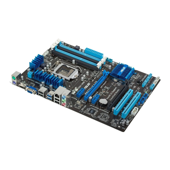
CMOS Power PCIEX16_2 Super PCI1 BIOS SATA3G_3 SATA3G_2 SATA3G_1 PCI2 SB_PWR USB78 USB56 SATA3G_4 SATA6G_2 SATA6G_1 COM1 SPDIF_OUT CLRTC F_PANEL AAFP DRCT SPEAKER 15 14 Refer to 2.2.1 Rear I/O connection for more information about rear panel connectors. ASUS P8Z77-V LK2... -
Page 20: Layout Contents
Layout contents Connectors/Jumpers/Slots/LED Page 1. CPU, Chassis and power fan connectors 1-23 (4-pin CPU_FAN, 4-pin CHA_FAN1/2, 3-pin PWR_FAN) 2. EATX power connectors (24-pin EATXPWR, 4-pin EATX12V) 1-26 3. Intel CPU socket ® 4. DDR3 DIMM sockets 5. USB 3.0 connector (20-1 pin USB3_34) 1-24 6. -
Page 21: System Memory
The figure illustrates the location of the DDR3 DIMM sockets: P8Z77-V LK2 P8Z77-V LK2 240-pin DDR3 DIMM sockets Recommended memory configurations We recommend that you install the memory modules from the blue slots for better overclocking ability. -
Page 22: Memory Configurations
3.4 Ai Tweaker menu for manual memory frequency adjustment. • For system stability, use a more efficient memory cooling system to support a full memory load (4 DIMMs) or overclocking condition. Visit the ASUS website for the latest QVL. Chapter 1: Product introduction... - Page 23 P8Z77-V LK2 Motherboard Qualified Vendors Lists (QVL) DDR3 2400MHz capability DIMM socket support Chip Chip (Optional) Vendors Part No. Size SS/DS Timing Voltage Brand 1 DIMM 2 DIMMs 4 DIMMs Transcend TX2400KLU-4GK (381850)(XMP) 4GB(2x 2GB) 1.65V • • * The 2400MHz memory modules above are supported on Intel 3rd generation processors by this ®...
- Page 24 P8Z77-V LK2 Motherboard Qualified Vendors Lists (QVL) DDR3 2000MHz capability DIMM socket support (Optional) Chip Chip Vendors Part No. Size Timing Voltage Brand 1 DIMM 2 DIMMs 4 DIMMs Apacer 78.AAGD5.9KD(XMP) 6GB(3 x 2GB) 9-9-9-27 1.65V • • • CORSAIR...
- Page 25 P8Z77-V LK2 Motherboard Qualified Vendors Lists (QVL) DDR3 1600MHz capability DIMM socket support Chip (Optional) Vendors Part No. Size Chip NO. Timing Voltage Brand 1 DIMM 2 DIMMs 4 DIMMs 3CCD-150 A-DATA AM2U16BC2P1 SS A-DATA • • • 9A EL1126T 1.65V-...
- Page 26 P8Z77-V LK2 Motherboard Qualified Vendors Lists (QVL) DDR3 1600MHz capability DIMM socket support Chip (Optional) Vendors Part No. Size Chip NO. Timing Voltage Brand 1 DIMM 2 DIMMs 4 DIMMs KHX1600C9D3T1BK3/ KINGSTON 12GB(3x4GB) DS - 9-9-9-27 1.65V • • •...
- Page 27 Hynix H5TQ2G83AFR • • • KVR1333D3N9/4G- KINGSTON KINGSTON D2568JENCPGD9U 1.5V • • • SP(low profile) MT4JTF12864AZ- Micron Micron OJD12D9LGQ • • • 1G4D1 MT8JTF12864AZ- Micron Micron 9FF22D9KPT • • • 1G4F1 (continued on the next page) ASUS P8Z77-V LK2 1-13...
- Page 28 DIMM socket support (Optional) Vendors Part No. Size Chip Brand Chip NO. Timing Voltage 1 DIMM 2 DIMMs 4 DIMMs MT8JTF25664AZ- Micron Micron OJD12D9LGK • • • 1G4D1 MT8JTF25664AZ- Micron MICRON IJM22 D9PFJ • • • 1G4M1 MT16JTF25664AZ- Micron Micron 9KF27D9KPT •...
- Page 29 P8Z77-V LK2 Motherboard Qualified Vendors Lists (QVL) DDR3 1066MHz capability DIMM socket support (Optional) Size SS/ Chip Vendors Part No. Chip NO. Timing Voltage Brand 1 DIMM 2 DIMMs 4 DIMMs Crucial CT12864BA1067.8FF 1GB SS Micron 9GF22D9KPT • • •...
-
Page 30: Expansion Slots
1.2.4 Expansion slots Unplug the power cord before adding or removing expansion cards. Failure to do so may cause you physical injury and damage motherboard components. P8Z77-V LK2 Slot No. Slot Description PCIe 2.0 x1_1 slot PCIe 3.0/2.0 x16_1 slot [blue] (at 16x mode) PCIe 2.0 x1_2 slot... -
Page 31: Irq Assignments For This Motherboard
– – – – RTL8111F shared – – – – – – – PCI Slot 1 – shared – – – – – – PCI Slot 2 – – shared – – – – – ASUS P8Z77-V LK2 1-17... -
Page 32: Jumpers
Normal Clear RTC (Default) P8Z77-V LK2 Clear RTC RAM To erase the RTC RAM: Turn OFF the computer and unplug the power cord. Move the jumper cap from pins 1-2 (default) to pins 2-3. Keep the cap on pins 2-3 for about 5~10 seconds, then move the cap back to pins 1-2. -
Page 33: Onboard Led
This connector is for a serial (COM) port. Connect the serial port module cable to this connector, then install the module to a slot opening at the back of the system chassis. PIN 1 P8Z77-V LK2 P8Z77-V LK2 Serial port (COM) connector The COM module is purchased separately. ASUS P8Z77-V LK2 1-19... - Page 34 Intel® Rapid Storage Technology through the onboard Intel® Z77 chipset. P8Z77-V LK2 P8Z77-V LK2 SATA 6.0Gb/s connectors • These connectors are set to [AHCI Mode] by default. If you intend to create a Serial ATA RAID set using these connectors, set the SATA Mode item in the BIOS to [RAID Mode].
- Page 35 480 Mbps connection speed. USB78 USB56 P8Z77-V LK2 PIN 1 PIN 1 P8Z77-V LK2 USB2.0 connectors Never connect a 1394 cable to the USB connectors. Doing so will damage the motherboard! The USB module cable is purchased separately. ASUS P8Z77-V LK2 1-21...
- Page 36 P8Z77-V LK2 HD-audio-compliant Legacy AC’97 pin definition compliant definition P8Z77-V LK2 Front panel audio connector • We recommend that you connect a high-definition front panel audio module to this connector to avail of the motherboard’s high-definition audio capability. • If you want to connect a high-definition front panel audio module to this connector, set the Front Panel Select item in the BIOS setup to [HD Audio];...
- Page 37 PWR_FAN CHA_FAN1 P8Z77-V LK2 P8Z77-V LK2 Fan connectors Do not forget to connect the fan cables to the fan connectors. Insufficient air flow inside the system may damage the motherboard components. These are not jumpers! Do not place jumper caps on the fan connectors! The CPU_FAN connector supports the CPU fan of maximum 1A (12 W) fan power.
- Page 38 USB 3.0 solution. USB3_34 P8Z77-V LK2 P8Z77-V LK2 USB3.0 Front panel connector You can connect the ASUS front panel USB 3.0 bracket to this connector to obtain the front panel USB 3.0 solution. 1-24 Chapter 1: Product introduction...
- Page 39 ® chipset. P8Z77-V LK2 P8Z77-V LK2 SATA 3.0Gb/s connectors • These connectors are set to [AHCI Mode] by default. If you intend to create a Serial ATA RAID set using these connectors, set the SATA Mode item in the BIOS to [RAID Mode].
- Page 40 • If you are uncertain about the minimum power supply requirement for your system, refer to the Recommended Power Supply Wattage Calculator at http://support.asus. com/PowerSupplyCalculator/PSCalculator.aspx?SLanguage=en-us for details. 1-26 Chapter 1: Product introduction...
-
Page 41: System Panel Connector (10-1 Pin Panel)
P8Z77-V LK2 PIN 1 HD_LED RESET P8Z77-V LK2 System panel connector • System power LED (2-pin PLED) This 2-pin connector is for the system power LED. Connect the chassis power LED cable to this connector. The system power LED lights up when you turn on the system power, and blinks when the system is in sleep mode. - Page 42 Speaker connector (4- pin SPEAKER) This 4-pin connector is for the chassis-mounted system warning speaker. The speaker allows you to hear system beeps and warnings. SPEAKER P8Z77-V LK2 PIN 1 P8Z77-V LK2 Speaker Out connector 1-28 Chapter 1: Product introduction...
-
Page 43: Basic Installation
Motherboard installation The diagrams in this section are for reference only. The motherboard layout may vary with models, but the installation steps are the same for all models. Install the I/O Shield to the chassis rear I/O panel. ASUS P8Z77-V LK2... - Page 44 Place the motherboard into the chassis, ensuring that its rear I/O ports are aligned to the chassis’ rear I/O panel. Chapter 2: Basic installation...
- Page 45 Place six screws into the holes indicated by circles to secure the motherboard to the chassis. P8Z77-V LK2 DO NOT overtighten the screws! Doing so can damage the motherboard. ASUS P8Z77-V LK2...
-
Page 46: Cpu Installation
2.1.2 CPU installation The LGA1156 CPU is incompatible with the LGA1155 socket. DO NOT install a LGA1156 CPU on the LGA1155 socket. Chapter 2: Basic installation... - Page 47 ASUS P8Z77-V LK2...
-
Page 48: Cpu Heatsink And Fan Assembly Installation
2.1.3 CPU heatsink and fan assembly installation Apply the Thermal Interface Material to the CPU heatsink and CPU before you install the heatsink and fan if necessary. To install the CPU heatsink and fan assembly Chapter 2: Basic installation... - Page 49 To uninstall the CPU heatsink and fan assembly ASUS P8Z77-V LK2...
-
Page 50: Dimm Installation
2.1.4 DIMM installation To remove a DIMM Chapter 2: Basic installation... -
Page 51: Atx Power Connection
2.1.5 ATX Power connection ASUS P8Z77-V LK2... -
Page 52: Sata Device Connection
2.1.6 SATA device connection 2-10 Chapter 2: Basic installation... -
Page 53: Expansion Card Installation
2.1.7 Expansion Card installation To install PCIe x16 cards To install PCIe x1 cards To install PCI cards ASUS P8Z77-V LK2 2-11... -
Page 54: Motherboard Rear And Audio Connections
Motherboard rear and audio connections 2.2.1 Rear I/O connection Rear panel connectors PS/2 Mouse port USB 3.0 ports 1 and 2 Video Graphics Adapter (VGA) port USB 2.0 ports 3 and 4 Intel LAN (RJ-45) port* HDMI port ® Audio I/O ports** PS/2 Keyboard port USB 2.0 ports 1 and 2 * and **: Refer to the tables on the next page for LAN port LED and audio port definitions. - Page 55 2-channel Rear Speaker Rear Speaker Light Blue Line In Rear Speaker Out Front Speaker Front Speaker Lime Line Out Front Speaker Out Pink Mic In Mic In Bass/Center Bass/Center Lime – – – Side Speaker Out ASUS P8Z77-V LK2 2-13...
-
Page 56: Audio I/O Connections
2.2.2 Audio I/O connections Audio I/O ports Connect to Headphone and Mic Connect to Stereo Speakers Connect to 2.1 channel Speakers 2-14 Chapter 2: Basic installation... - Page 57 Connect to 4.1 channel Speakers Connect to 5.1 channel Speakers Connect to 7.1 channel Speakers ASUS P8Z77-V LK2 2-15...
-
Page 58: Starting Up For The First Time
Starting up for the first time After making all the connections, replace the system case cover. Ensure that all switches are off. Connect the power cord to the power connector at the back of the system chassis. Connect the power cord to a power outlet that is equipped with a surge protector. Turn on the devices in the following order: Monitor External SCSI devices (starting with the last device on the chain) -
Page 59: Bios Setup
BIOS setup Knowing BIOS The new ASUS UEFI BIOS is a Unified Extensible Interface that complies with UEFI architecture, offering a user-friendly interface that goes beyond the traditional keyboard- only BIOS controls to enable a more flexible and convenient mouse input. You can easily navigate the new UEFI BIOS with the same smoothness as your operating system. -
Page 60: Bios Setup Program
BIOS setup program Use the BIOS Setup to update the BIOS or configure its parameters. The BIOS screen include navigation keys and brief onscreen help to guide you in using the BIOS Setup program. Entering BIOS at startup To enter BIOS Setup at startup: •... -
Page 61: Ez Mode
• The boot device options vary depending on the devices you installed to the system. The Boot Menu(F8) button is available only when the boot device is installed to the • system. ASUS P8Z77-V LK2... -
Page 62: Advanced Mode
3.2.2 Advanced Mode The Advanced Mode provides advanced options for experienced end-users to configure the BIOS settings. The figure below shows an example of the Advanced Mode. Refer to the following sections for the detailed configurations. To access the Advanced Mode, click Exit, then select Advanced Mode. Back button Menu items Menu bar... -
Page 63: Menu Items
You cannot select an item that is not user-configurable. A configurable field is highlighted when selected. To change the value of a field, select it and press <Enter> to display a list of options. ASUS P8Z77-V LK2... -
Page 64: Main Menu
Main menu The Main menu screen appears when you enter the Advanced Mode of the BIOS Setup program. The Main menu provides you an overview of the basic system information, and allows you to set the system date, time, language, and security settings. EFI BIOS Utility - Advanced Mode Exit Main... -
Page 65: Administrator Password
The User Password item on top of the screen shows the default Not Installed. After you set a password, this item shows Installed. To set a user password: Select the User Password item and press <Enter>. From the Create New Password box, key in a password, then press <Enter>. Confirm the password when prompted. ASUS P8Z77-V LK2... -
Page 66: Ai Tweaker Menu
To change a user password: Select the User Password item and press <Enter>. From the Enter Current Password box, key in the current password, then press <Enter>. From the Create New Password box, key in a new password, then press <Enter>. Confirm the password when prompted. - Page 67 Use the <+> and <-> keys to adjust the value. You can also key in the desired value using the numeric keypad. The values range from 80.0MHz to 300.0MHz. ASUS MultiCore Enhancement [Enabled] [Enabled] Default set to [Enabled] for maximum performance under XMP/Manual/ User-defined memory frequency mode.
- Page 68 Internal PLL Overvoltage [Auto] Allows you to set the Internal PLL Overvoltage. Configuration options: [Auto] [Enabled] [Disabled]. CPU bus speed : DRAM speed ratio mode [Auto] Allows you to set the CPU bus speed to DRAM speed ratio mode. [Auto] DRAM speed is set to the optimized settings.
- Page 69 Use <+> and <-> key to adjust the value at 0.125A increment. . Secondary Plane Current Limit [Auto] Maximum instantaneous current allowed at any given time for Internal Graphics cores Use <+> and <-> key to adjust the value at 0.125A increment. ASUS P8Z77-V LK2 3-11...
- Page 70 DIGI+ VRM CPU Load-Line Calibration [Auto] Load-line is defined by Intel VRM spec and affects CPU voltage. The CPU working voltage will decrease proportionally to CPU loading. Higher value gets a higher voltage and better overclocking performance, but increases the CPU and VRM thermal. This item allows you to adjust the voltage range from the following percentages to boost the system performance: 0% (Regular), 25% (Medium), 50% (High), 75% (Ultra High) and 100% (Extreme).
- Page 71 Current Capability [100%] Allows you to set the iGPU Current Capability. Configuration options: [100%] [110%] [120%] [130%] DO NOT remove the thermal module while changing the DIGI+ VRM related parrameters . The thermal conditions should be monitored. ASUS P8Z77-V LK2 3-13...
- Page 72 CPU Voltage [Offset Mode] [Manual Mode] Allows you to set a fixed CPU voltage. [Offset Mode] Allows you to set the Offset voltage. CPU Offset Mode Sign [+] This item appears only when you set the CPU Voltage item to [Offset Mode]. To offset the voltage by a positive value.
- Page 73 Allows you to set the CPU and PCH PLL voltage. The values range from 1.80V to 1.90V with a 0.1V interval. Configuration options: [Auto] [+0.1V] CPU Spread Spectrum [Auto] [Auto] Automatic configuration. [Disabled] Enhances the BCLK overclocking ability. [Enabled] Sets to [Enabled] for EMI control. ASUS P8Z77-V LK2 3-15...
-
Page 74: Advanced Menu
Advanced menu The Advanced menu items allow you to change the settings for the CPU and other system devices. Be cautious when changing the settings of the Advanced menu items. Incorrect field values can cause the system to malfunction. 3.5.1 CPU Configuration The items in this menu show the CPU-related information that the BIOS automatically detects. - Page 75 Allows a hardware platform to run multiple operating systems separately and simultaneously, enabling one system to virtually function as several systems. [Disabled] Disables this function. Adjacent Cache Line Prefetch [Enabled] [Enabled] Allows a hardware platform to perform adjacent cache line prefetching. [Disabled] Disables this function. ASUS P8Z77-V LK2 3-17...
-
Page 76: Cpu Power Management Configuration
CPU Power Management Configuration CPU Ratio [Auto] Allows you to set the ratio between the CPU Core Clock and the BCLK Frequency. Use <+> and <-> keys to adjust the ratio. The valid value ranges vary according to your CPU model. Enhanced Intel SpeedStep Technology [Enabled] Allows you to enable or disable the Enhanced Intel SpeedStep Technology (EIST). -
Page 77: Pch Configuration
S3 entry. Key in the desired value using the numeric keypad. Intel Smart Connect Technology ® ISCT Configuration [Disabled] Allows you to enable or disable the ISCT configuration. Configuration options: [Enabled] [Disabled] ASUS P8Z77-V LK2 3-19... -
Page 78: Sata Configuration
3.5.3 SATA Configuration While entering Setup, the BIOS automatically detects the presence of SATA devices. The SATA Port items show Not Present if no SATA device is installed to the corresponding SATA port. SATA Mode Selection [AHCI] Allows you to set the SATA configuration. [IDE Mode] Set to [IDE Mode] when you want to use the Serial ATA hard disk drives as Parallel ATA physical storage devices. -
Page 79: System Agent Configuration
64MB. Configuration options: [Disabled] [Enabled] NB PCIe Configuration Allows you to configure the NB PCI Express settings. PCIE x16_1 [Auto] Allows you to set the PCIE x16_1 link speed. Configuration options: [Auto] [Gen1] [Gen2] [Gen3] ASUS P8Z77-V LK2 3-21... -
Page 80: Usb Configuration
3.5.5 USB Configuration The items in this menu allow you to change the USB-related features. The USB Devices item shows the auto-detected values. If no USB device is detected, the item shows None. Legacy USB Support [Enabled] [Enabled] Enables the support for USB devices on legacy operating systems (OS). [Disabled] The USB devices can be used only for the BIOS setup program. -
Page 81: Onboard Devices Configuration
Change Settings [IO=3F8h; IRQ=4] This item appears only when you set the Serial Port to [Enabled] and allows you to select the Serial Port base address. Configuration options: [IO=3F8h; IRQ=4] [IO=2F8h; IRQ=3] [IO=3E8h; IRQ=4] [IO=2E8h; IRQ=3] ASUS P8Z77-V LK2 3-23... -
Page 82: Apm
3.5.7 Restore AC Power Loss [Power Off] [Power On] The system goes into on state after an AC power loss. [Power Off] The system goes into off state after an AC power loss. [Last State] The system goes into either off or on state, whatever the system state was before the AC power loss. -
Page 83: Network Stack
N/A. Select Ignore if you do not wish to display the detected speed. CPU Voltage, 3.3V Voltage, 5V Voltage, 12V Voltage The onboard hardware monitor automatically detects the voltage output through the onboard voltage regulators. Select Ignore if you do not want to detect this item. ASUS P8Z77-V LK2 3-25... - Page 84 CPU Q-Fan Control [Enabled] [Disabled] Disables the CPU Q-Fan control feature. [Enabled] Enables the CPU Q-Fan control feature. CPU Fan Speed Low Limit [600 RPM] This item appears only when you enable the CPU Q-Fan Control feature and allows you to disable or set the CPU fan warning speed.
- Page 85 The values range from 0% to 100%. When the chassis temperature is under 40ºC, the chassis fan will operate at the minimum duty cycle. Anti Surge Support [Enabled] This item allows you to enable or disable the Anti Surge function. Configuration options: [Disabled] [Enabled] ASUS P8Z77-V LK2 3-27...
-
Page 86: Boot Menu
[Disabled] Disables the full screen logo display feature. Set this item to [Enabled] to use the ASUS MyLogo 2™ feature. Post Delay Time [3 sec] Allows you to set the waiting time for the system to display the post logo. Configuration options: [0 sec] [1 sec] [2 sec] [3 sec] [4 sec] [5 sec] [6 sec] [7 sec] [8 sec] [9 sec] [10 sec] Wait For ‘F1’... - Page 87 The following four items appear only when you set Launch CSM to [Enabled]. Boot option filter [UEFI and Legacy] Configuration option: [UEFI and Legacy] [Legacy only] [UEFI only] Launch PXE OpROM policy [Legacy first] Configuration option: [DO NOT launch] [Legacy first] [UEFI first] ASUS P8Z77-V LK2 3-29...
-
Page 88: Security Boot Parameters
• To select the boot device during system startup, press <F8> when ASUS Logo appears. • To access Windows OS in Safe Mode, do any of the following: - Press <F5>... -
Page 89: Tools Menu
<Enter> to display the submenu. ASUS EZ Flash 2 utility Allows you to run ASUS EZ Flash 2. When you press <Enter>, a confirmation message appears. Use the left/right arrow key to select between [Yes] or [No], then press <Enter> to confirm your choice. -
Page 90: Exit Menu
This option allows you to exit the Setup program without saving your changes. When you select this option or if you press <Esc>, a confirmation window appears. Select Yes to discard changes and exit. ASUS EZ Mode This option allows you to enter the EZ Mode screen. Launch EFI Shell from filesystem device This option allows you to attempt to launch the EFI Shell application (shellx64.efi) from one of... -
Page 91: Updating Bios
BIOS in the future. Copy the original motherboard BIOS using the ASUS Update or BIOS Updater utilities. 3.10.1 ASUS Update utility The ASUS Update is a utility that allows you to manage, save, and update the motherboard BIOS in Windows environment. The ASUS Update utility allows you to: ®... -
Page 92: Updating The Bios Through The Internet
Updating the BIOS through the Internet To update the BIOS through the Internet: From the ASUS Update screen, select Update BIOS from Internet, and then Model Name click Next. P8Z77-V LK2 Version 0206 Release Date 06/20/2012 Select the ASUS FTP site nearest you to avoid network traffic. -
Page 93: Updating The Bios Through A Bios File
The screenshots in this section are for reference only. The actual BIOS information vary by models. • Refer to the software manual in the support DVD or visit the ASUS website at www. asus.com for detailed software configuration. ASUS P8Z77-V LK2... -
Page 94: Asus Ez Flash 2 Utility
3.10.2 ASUS EZ Flash 2 utility The ASUS EZ Flash 2 feature allows you to update the BIOS without having to use a bootable floppy disk or an OS-based utility. Before you start using this utility, download the latest BIOS from the ASUS website at www.asus.com. -
Page 95: Asus Crashfree Bios 3 Utility
The BIOS file in the motherboard support DVD may be older than the BIOS file published on the ASUS official website. If you want to use the newer BIOS file, download the file at support.asus.com and save it to a USB flash drive. -
Page 96: Asus Bios Updater
3.10.4 ASUS BIOS Updater The ASUS BIOS Updater allows you to update BIOS in DOS environment. This utility also allows you to copy the current BIOS file that you can use as a backup when the BIOS fails or gets corrupted during the updating process. - Page 97 Update ROM BOARD: Unknown BOARD: P8Z77-V LK2 VER: Unknown VER: 0215 DATE: Unknown DATE: 06/20/2012 PATH: P8Z77VLK2.CAP 4194304 2012-06-20 17:30:48 Note [Enter] Select or Load [Tab] Switch [V] Drive Info [Up/Down/Home/End] Move [B] Backup [Esc] Exit ASUS P8Z77-V LK2 3-39...
- Page 98 Press <Tab> to switch between screen fields and use the <Up/Down/Home/End> keys to select the BIOS file and press <Enter>. BIOS Updater checks the selected BIOS file and prompts you to confirm BIOS update. Are you sure to update BIOS? Select Yes and press <Enter>.
-
Page 99: Software Support
• This motherboard supports Windows 7 / 64-bit 7 operating systems (OS). To take ® advantage of all the features that come with this motherboard, ASUS strongly recommends using Windows ® • Motherboard settings and hardware options vary. Use the setup procedures presented in this chapter for reference only. -
Page 100: Obtaining The Software Manuals
The software manual files are in Portable Document Format (PDF). Install the Adobe® Acrobat® Reader from the Utilities menu before opening the files. Click the Manual tab. Click ASUS Motherboard Utility Guide from the manual list on the left. -
Page 101: Software Information
4.3.1 AI Suite II AI Suite II is an all-in-one interface that integrates several ASUS utilities and allows users to launch and operate these utilities simultaneously. Installing AI Suite II To install AI Suite II on your computer: Place the support DVD to the optical drive. -
Page 102: Turbov Evo
To launch AI Suite II, click Tool > TurboV EVO on the AI Suite II main menu bar. Refer to the software manual in the support DVD or visit the ASUS website at www.asus. com for detailed software configuration. - Page 103 Using Advanced Mode Click on the Advanced Mode tab to adjust the advanced voltage settings. Advanced Voltage mode Adjustment Target values bars Undoes all the Current values changes Click to restore Applies all all startup the changes settings immediately ASUS P8Z77-V LK2...
- Page 104 CPU Ratio Allows you to manually adjust the CPU ratio. • The first time you use CPU Ratio, go to AI Tweaker > CPU Power Management in BIOS and set the Turbo Ratio item to [Maximum Turbo Ratio setting in OS]. •...
-
Page 105: Auto Tuning
Auto Tuning ASUS TurboV EVO provides you with a Fast Tuning mode. • The overclocking result varies with the CPU model and the system configuration. • We recommend that you set up a better thermal environment to prevent overheating from damaging the motherboard. - Page 106 After the system restarts, a message appears indicating that auto-tuning is successful. Click OK to exit. Chapter 4: Software support...
-
Page 107: Digi+ Vrm
4.3.3 DIGI+ VRM ASUS DIGI+ VRM allows you to adjust VRM voltage and frequency modulation to enhance reliability and stability. It also provides the highest power efficiency while generating less heat to prolong component lifespan and minimize power loss. After installing AI Suite II from the motherboard support DVD, launch DIGI+ VRM by clicking Tool >... - Page 108 The actual performance boost may vary depending on your CPU specification. • Do not remove the thermal module. The thermal conditions should be monitored. Refer to the software manual in the support DVD or visit the ASUS website at www.asus.com for detailed software configuration. Chapter 4: Software support...
-
Page 109: Epu
*Select From the Last Reset to show the total CO2 that has been reduced since you click the Clear button • Refer to the software manual in the support DVD or visit the ASUS website at www. asus.com for detailed software configuration. ASUS P8Z77-V LK2... -
Page 110: Fan Xpert
70 • User: allows you to configure the CPU fan profile under certain limitations. Refer to the software manual in the support DVD or visit the ASUS website at www.asus.com for detailed software configuration. Chapter 4: Software support... -
Page 111: Probe Ii
• Click Monitor > Sensor on the AI Suite II main menu bar and the system status will appear on the right panel. • Refer to the software manual in the support DVD or visit the ASUS website at www.asus.com for detailed software configuration. -
Page 112: Sensor Recorder
4.3.7 Sensor Recorder Sensor Recorder monitors the changes in the system voltage, temperature, and fan speed on a timeline. The History Record function allows you to designate specific time spans on record to keep track of the three system statuses for certain purposes. Launching Sensor Recorder To launch Sensor Recorder, click Tool >... - Page 113 To track the recorded contents, set Type/ Date/ Select display items to display the history details. Click on Monitor > Sensor on the AI Suite II main menu bar and a highlight of the system statuses will appear on the right panel. ASUS P8Z77-V LK2 4-15...
-
Page 114: Usb 3.0 Boost
Turbo mode or UASP mode (if UASP is supported by the USB 3.0 device). You can manually switch the USB 3.0 mode back to Normal mode at any time. • Refer to the software manual in the support DVD or visit the ASUS website at www.asus.com for detailed software configuration. •... -
Page 115: Ai Charger
Ai Charger Ai Charger is a unique software that allows you to quickly charge your Apple devices such as the iPod, iPhone, and iPad on your ASUS computer’s USB 2.0 / USB 3.0 port. • There is no settings screen for the Ai Charger. After installation on your computer, the Ai Charger icon will appear on the Windows taskbar. -
Page 116: Network Icontrol
4.3.10 Network iControl ASUS Network iControl, a one-stop setup network control center that gives you the EZ Start, Quick Connection, and EZ Profile functions, makes it easier for you to manage your network bandwidth. It also allows you to automatically connect to a PPPoE network for a more convenient online experience. - Page 117 Open Network and Sharing Center. Right-click the PPPoE Connection, and select Properties. Click the Options tab, and deselect Prompt for name and password, certificate, etc. Click OK to complete the auto PPPoE connection settings. ASUS P8Z77-V LK2 4-19...
- Page 118 • You only need to configure the PPPoE connection settings once. • Obtain the necessary information about your PPPoE connection from your network provider. Configuring the Quick Connection To configure the auto-PPPoE connection: Click the Quick Connection tab. Tick Automatically connect online anytime option, then select the connection name in the Connection Name dropdown box.
-
Page 119: Asus Update
Windows environment. ® Launching ASUS Update To launch ASUS Update, click Update > ASUS Update on the AI Suite II main menu bar. Using ASUS Update Select any of these options to update the BIOS: • Update BIOS from Internet Allows you to download the latest BIOS version from the ASUS website at www.asus. -
Page 120: Mylogo2
MyLogo2 allows you to customize the boot logo, which is the image that appears on the screen during the Power On Self Tests (POST). Launching ASUS Update To launch MyLogo2, click Update > MyLogo on the AI Suite II main menu bar. -
Page 121: Audio Configurations
If the Realtek audio software is correctly installed, you will ® find the Realtek HD Audio Manager icon on the taskbar. ® Double-click on the icon to display the Realtek HD Audio Manager. Realtek HD Audio Manager ® ASUS P8Z77-V LK2 4-23... - Page 122 Minimize button Control settings window Information button • Refer to the software manual in the support DVD or visit the ASUS website at www. asus.com for detailed software configuration. • Due to Intel Z77 platform does not support Windows Vista™, Realtek HD Audio ®...
-
Page 123: Raid Support
With the RAID 10 configuration you get all the benefits of both RAID 0 and RAID 1 configurations. Use four new hard disk drives or use an existing drive and three new drives for this setup. ASUS P8Z77-V LK2... -
Page 124: Installing Serial Ata Hard Disks
5.1.2 Installing Serial ATA hard disks The motherboard supports Serial ATA hard disk drives. For optimal performance, install identical drives of the same model and capacity when creating a disk array. To install the SATA hard disks for a RAID configuration: Install the SATA hard disks into the drive bays. -
Page 125: Intel ® Rapid Storage Technology Option Rom Utility
The RAID BIOS setup screens shown in this section are for reference only and may not exactly match the items on your screen. The utility supports maximum four hard disk drives for RAID configuration. ASUS P8Z77-V LK2... - Page 126 Creating a RAID set To create a RAID set: From the utility main menu, select 1. Create RAID Volume and press <Enter>. The following screen appears: Intel(R) Rapid Storage Technology - Option ROM - v10.5.1.1070 Copyright(C) 2003-10 Intel Corporation. All Rights Reserved. [ CREATE VOLUME MENU ] Name: Volume0...
- Page 127 WARNING: ALL DATA ON SELECTED DISKS WILL BE LOST. Are you sure you want to create this volume? (Y/N): Press <Y> to create the RAID volume and return to the main menu, or <N> to go back to the CREATE VOLUME menu. ASUS P8Z77-V LK2...
- Page 128 Deleting a RAID set Be cautious when deleting a RAID set. You will lose all data on the hard disk drives when you delete a RAID set. To delete a RAID set: From the utility main menu, select 2. Delete RAID Volume and press <Enter>. The following screen appears: [ DELETE VOLUME MENU ] Name...
- Page 129 From the utility main menu, select 5. Exit, and then press <Enter>. The following warning message appears: [ CONFIRM EXIT ] Are you sure you want to exit? (Y/N): Press <Y> to exit or press <N> to return to the utility main menu. ASUS P8Z77-V LK2...
-
Page 130: Creating A Raid Driver Disk
Creating a RAID driver disk A floppy disk with the RAID driver is required when installing a Windows operating system ® on a hard disk drive that is included in a RAID set. • The motherboard does not provide a floppy drive connector. You have to use a USB floppy disk drive when creating a SATA RAID driver disk. -
Page 131: Installing The Raid Driver During Windows ® Os Installation
Follow the succeeding screen instructions to complete the installation. Before loading the RAID driver from a USB flash drive, you have to use another computer to copy the RAID driver from the support DVD to the USB flash drive. ASUS P8Z77-V LK2... -
Page 132: Using A Usb Floppy Disk Drive
5.2.4 Using a USB floppy disk drive Due to OS limitation, Windows XP may not recognize the USB floppy disk drive when you ® install the RAID driver from a floppy disk during the OS installation. To solve this issue, add the USB floppy disk drive’s Vendor ID (VID) and Product ID (PID) to the floppy disk containing the RAID driver. - Page 133 = “USB\VID_xxxx&PID_xxxx”, “usbstor” [HardwareIds.scsi.iaAHCI_ DesktopWorkstationServer] id= “PCI\VEN_8086&DEV_1C02&CC_0106”,”iaStor” id= “USB\VID_03EE&PID_6901”, “usbstor” [HardwareIds.scsi.iaStor_ DesktopWorkstationServer] id= “PCI\VEN_8086&DEV_2822&CC_0104”,”iaStor” id= “USB\VID_03EE&PID_6901”, “usbstor” Add the same line to both sections. The VID and PID vary with different vendors. Save and exit the file. ASUS P8Z77-V LK2 5-11...
- Page 134 Chapter 5: RAID configurations 5-12...
-
Page 135: Intel ® Technologies
5. DRAM: To enable Intel Rapid Start Technology, DRAM size smaller than 8GB is ® required. Ensure to enable the acceleration of Intel Smart Response Technology before ® creating the partition for the Intel Rapid Start Technology. ® ASUS P8Z77-V LK2... - Page 136 SSD Capacity Requirements SSD Partition Capacity System DRAM Requirements Intel Rapid Start ® Intel Smart Response 20GB 20GB 20GB ® Separate 20GB Separate Separate Intel Smart Response and 2GB 20GB and 4GB 20GB and 8GB ® partition partition partition Intel Rapid Start (SSD size >...
-
Page 137: Intel ® Smart Response Technology
Select which HDD for caching. d. Enhanced mode: WRITE THROUGH, write to SSD and HDD at the same time. Maximized mode: WRITE BACK, write to SSD and write back to HDD in a later time. ASUS P8Z77-V LK2... -
Page 138: Intel ® Rapid Start Technology
Select Disable Acceleration to disable this function, and select Change Mode to switch acceleration mode to Enhanced/ Maximized. > = ® • To enable Intel Smart Response Technology, you need at least one SSD ( 20GB) and a HDD, and only one SSD can be assigned for caching. •... - Page 139 DRAM memory (1GB = 1024MB). Click Shrink. Go to Start > Control Panel > System and Security > System, and check the DRAM size information. The unallocated volume is allocated to the selected disk. ASUS P8Z77-V LK2...
- Page 140 To launch the disk partitioning tool, click Start > Programs > Accessories > Command Prompt tool. Type diskpart and press Enter. In the diskpart prompt, type list disk after DISKPART, and press Enter. Select the disk with the unallocated volume by typing select disk x (x = disk number), and press Enter .
- Page 141 Rapid Start ® Manager to enable or disable the Intel Rapid Start ® Technology. Click the Show hidden icons arrow from the right side of the task bar, and click Intel Rapid Start ® Technology Manager icon. ASUS P8Z77-V LK2...
-
Page 142: Recovering The Partition
Tick On in the Status field to enable the function, and click Save. Select and click to enable or disable the function Click to enable or disable battery saving mode. This function only applies to notebooks. Click to enable or disable the timer. When enabled, move Click to save the Click to cancel the the scroll bar to the desired time. - Page 143 In the desktop, click Start, right-click Computer, and click Manage. In the Computer Management window, click Disk Management, right click the shrinked new volume, and select Extend Volume. As the Extend Volume Wizard appears, click Next. ASUS P8Z77-V LK2...
-
Page 144: Intel ® Smart Connect Technology
Click Next after selecting the default selected disk. Extend volume setup is completed. Click Finish to recover the Intel Rapid Start ® Technology partition. Reboot the system after deleting the partition. Go to Start > Control Panel > Programs > Programs and Features > to remove the Intel Rapid Start Manager for the complete deletion of Intel Rapid Start Technology. - Page 145 When updating is Click to enable enabled, click to or disable the reset all settings function to default. When the scroll bar is activated, adjust the waking up time period for Internet data update. ASUS P8Z77-V LK2 6-11...
- Page 146 To disable the updating function, click Disable Updating. Clicking this button automatically disables the configuration in the Advanced tab. To reset to defaults, click Reset All to Defaults. In the Advanced tab, set up the schedule during low power usage time period for power saving.
-
Page 147: Multiple Gpu Support
For Windows XP, go to Control Panel > Add/Remove Programs. For Windows 7, go to Control Panel > Programs and Features. Select your current graphics card driver/s. For Windows XP, select Add/Remove. For Windows 7, select Uninstall. Turn off your computer. ASUS P8Z77-V LK2... -
Page 148: Installing Two Crossfirex™ Graphics Cards
7.1.3 Installing two CrossFireX™ graphics cards The following pictures are for reference only. The graphics cards and the motherboard layout may vary with models, but the installation steps remain the same. Prepare two CrossFireX-ready graphics cards. Insert the two graphics card into the PCIEX16 slots. -
Page 149: Installing The Device Drivers
Launching the AMD Catalyst Control Center To launch the AMD Catalyst Control Center: Right-click on the Windows desktop and select ® Catalyst Control Center. Click Catalyst Control Center to configure the displays and settings of your AMD graphic cards. ASUS P8Z77-V LK2... - Page 150 Enabling Dual CrossFireX technology In the Catalyst Control Center window, click Performance > AMD CrossFireX Select Enable CrossFireX Select a GPU combination from the drop-down list. Click Apply to save and activate the GPU settings made. Chapter 7: Multiple GPU support...
-
Page 151: Appendices
The use of shielded cables for connection of the monitor to the graphics card is required to assure compliance with FCC regulations. Changes or modifications to this unit not expressly approved by the party responsible for compliance could void the user’s authority to operate this equipment. ASUS P8Z77-V LK2... -
Page 152: Canadian Department Of Communications Statement
IC: Canadian Compliance Statement Complies with the Canadian ICES-003 Class B specifications. This device complies with RSS 210 of Industry Canada. This Class B device meets all the requirements of the Canadian interference-causing equipment regulations. This device complies with Industry Canada license exempt RSS standard(s). Operation is subject to the following two conditions: (1) this device may not cause interference, and (2) this device must accept any interference, including interference that may cause undesired operation of the device. - Page 153 ASUS Recycling/Takeback Services ASUS recycling and takeback programs come from our commitment to the highest standards for protecting our environment. We believe in providing solutions for you to be able to responsibly recycle our products, batteries, other components as well as the packaging materials.
-
Page 154: Asus Contact Information
+1-812-282-3777 +1-510-608-4555 Web site usa.asus.com Technical Support Telephone +1-812-282-2787 Support fax +1-812-284-0883 Online support support.asus.com ASUS COMPUTER GmbH (Germany and Austria) Address Harkort Str. 21-23, D-40880 Ratingen, Germany +49-2102-959911 Web site www.asus.de Online contact www.asus.de/sales Technical Support Telephone +49-1805-010923* Support Fax... - Page 155 ASUS P8Z77-V LK2...
- Page 156 Appendices...
Need help?
Do you have a question about the P8Z77-V LK2 and is the answer not in the manual?
Questions and answers