Asus P8Z77-V PREMIUM Manual
Lga1155 socket motherboard
Hide thumbs
Also See for P8Z77-V PREMIUM:
- User manual (174 pages) ,
- User manual (26 pages) ,
- User manual (1 page)
Table of Contents
Advertisement
Quick Links
Advertisement
Table of Contents

Related Manuals for Asus P8Z77-V PREMIUM


Summary of Contents for Asus P8Z77-V PREMIUM
- Page 1 P8Z77-V PREMIUM...
- Page 2 Product warranty or service will not be extended if: (1) the product is repaired, modified or altered, unless such repair, modification of alteration is authorized in writing by ASUS; or (2) the serial number of the product is defaced or missing.
-
Page 3: Table Of Contents
Contents Safety information ... vii About this guide ... viii P8Z77-V PREMIUM Windows P8Z77-V PREMIUM specifications summary ... xi Package contents ... xvi Installation tools and components ... xvii Chapter 1: Product introduction Special features... 1-1 1.1.1 Product highlights... 1-1 1.1.2... - Page 4 USB Configuration ... 3-28 Onboard Devices Configuration ... 3-29 APM ... 3-31 Network Stack ... 3-32 ASUS EZ Flash 2 Utility ... 3-38 ASUS O.C. Profile ... 3-38 ASUS SPD Information ... 3-39 ASUS Update ... 3-41 ASUS EZ Flash 2 ... 3-44 ASUS CrashFree BIOS 3 ...
- Page 5 DIGI+ Power Control ... 4-9 4.3.4 EPU ... 4-13 4.3.5 USB 3.0 Boost... 4-14 4.3.6 USB BIOS Flashback Wizard... 4-15 4.3.7 ASUS SSD Caching II ... 4-17 4.3.8 Ai Charger+ ... 4-19 4.3.9 Probe II... 4-20 4.3.10 Sensor Recorder ... 4-21 4.3.11 ASUS Update ...
- Page 6 ® 7.1.1 7.1.2 7.1.3 Appendices Notices ... A-1 ASUS contact information ... A-5 Installing three CrossFireX™ graphics cards ... 6-3 Installing four CrossFireX™ graphics cards ... 6-4 Installing the device drivers ... 6-5 Enabling the AMD CrossFireX™ technology ... 6-5 ®...
-
Page 7: Electrical Safety
Safety information Electrical safety • To prevent electrical shock hazard, disconnect the power cable from the electrical outlet before relocating the system. • When adding or removing devices to or from the system, ensure that the power cables for the devices are unplugged before the signal cables are connected. If possible, disconnect all power cables from the existing system before you add a device. -
Page 8: About This Guide
Refer to the following sources for additional information and for product and software updates. ASUS websites The ASUS website provides updated information on ASUS hardware and software products. Refer to the ASUS contact information. Optional documentation Your product package may include optional documentation, such as warranty flyers, that may have been added by your dealer. -
Page 9: Conventions Used In This Guide
Conventions used in this guide To ensure that you perform certain tasks properly, take note of the following symbols used throughout this manual. DANGER/WARNING: Information to prevent injury to yourself when trying to complete a task. CAUTION: Information to prevent damage to the components when trying to complete a task IMPORTANT: Instructions that you MUST follow to complete a task. -
Page 10: P8Z77-V Premium Windows ® Os Restrictions
Disk Unlocker ASUS SSD Caching II ASUS AI Suite II Exclusive Features MemOK! USB 3.0 Boost (for ASUS extra USB 3.0 ports) USB 3.0 Boost (for Intel® Native USB 3.0 ports) Wi-Fi GO! Network iControl DTS UltraPC II DTS Connect LucidLogix Virtu MVP •... -
Page 11: P8Z77-V Premium Specifications Summary
* The Intel Turbo Boost Technology 2.0 support depends on the CPU ® types. ** Refer to www.asus.com for Intel CPU support list Intel Z77 Express Chipset ® 4 x DIMM, max. 32GB, DDR3 2800 (O.C.)* / 2600 (O.C.)* / 2400 (O.C.)* / 2200(O.C.) / 2133(O.C.) / 1866(O.C.) / 1600 / 1333... - Page 12 64 Mb Flash ROM, UEFI AMI BIOS, PnP, DMI 2.0, WfM 2.0, SM BIOS 2.5, ACPI 2.0a, Multi-language BIOS, ASUS EZ Flash 2, ASUS CrashFree BIOS 3, F12 PrintScreen function, F3 Shortcut function, and ASUS DRAM SPD (Serial Presence Detect) memory information WfM 2.0, DMI 2.0, WOL by PME, PXE...
- Page 13 P8Z77-V PREMIUM specifications summary ASUS unique features ASUS Dual Intelligent Processors 3 - SMART DIGI+ Power Control SMART DIGI+ - SMART DIGI+ Key quickly delivers a higher VRM frequency, voltage, and current for superior CPU/iGPU/ DRAM overclocking performance with one switch.
- Page 14 - ASUS C.P.R.(CPU Parameter Recall) 1 x Thunderbolt port 1 x DisplayPort 1 x HDMI port 1 x BT4 connector for ASUS Wi-Fi GO! card (Wi-Fi 802.11 a/b/g/n and Bluetooth v4.0/3.0+HS) 1 x Optical S/PDIF Out port 2 x eSATA ports...
- Page 15 P8Z77-V PREMIUM specifications summary Internal I/O connectors Support DVD contents Form factor Specifications are subject to change without notice. 1 x 19-pin USB 3.0/2.0 connector supports additional 2 USB ports 2 x USB 2.0/1.1 connectors support additional 4 USB ports 6 x SATA 6.0 Gb/s connectors (2 x gray;...
-
Page 16: Package Contents
Check your motherboard package for the following items. ASUS P8Z77-V PREMIUM motherboard 4 x Serial ATA 6.0 Gb/s cables 2 x Serial ATA 3.0 Gb/s cables 1 x ASUS Wi-Fi GO! card (Wi-Fi 802.11 a/b/g/n and Bluetooth v4.0/3.0+HS) 1 x 4-WAY SLI card •... -
Page 17: Installation Tools And Components
Installation tools and components 1 bag of screws Philips (cross) screwdriver PC chassis Power supply unit Intel LGA 1155 CPU Intel LGA 1155 compatible CPU Fan DIMM SATA hard disk drive SATA optical disc drive (optional) Graphics card (optional) The tools and components in the table above are not included in the motherboard package. xvii... - Page 18 xviii...
-
Page 19: Chapter 1: Product Introduction
With the Intel Z77 platform to optimize the PCIe allocation of multiple GPUs, it supports up to four graphic cards in both SLI or CrossFireX configuration. ASUS P8Z77-V PREMIUM , and Celeron processors. It utilizes the serial point-to- ®... -
Page 20: Intel ® Smart Response Technology
Dual Intelligent Processors 3 with SMART DIGI+ Power Control Together with the ASUS pioneered twin onboard chips, TPU (TurboV Processing Unit) and EPU (Energy Processing Unit), ASUS Dual Intelligent Processors feature SMART DIGI+ Power Control, which includes multiple digital voltage controllers that allow ultra-precise auto- tuning for the CPU, iGPU and DRAM. -
Page 21: Asus Exclusive Features
ASUS Exclusive Features Wi-Fi GO! ASUS Wi-Fi GO! leads the way to a more enjoyable home entertainment. With ASUS Wi-Fi GO!, you can wirelessly stream media files to DLNA devices, remotely control and access your computer using your mobile device, and easily transfer files between your computer and mobile device. -
Page 22: Network Icontrol
ASUS Quiet Thermal Solution ASUS Fan Xpert 2 ASUS Fan Xpert 2 provides customizable settings for a cooler and quieter computing environment. With its Fan Auto Tuning feature, ASUS Fan Xpert 2 automatically detects and tweaks all fan speeds, and provides you with optimized fan settings based on the fans’... -
Page 23: Other Special Features
The motherboard is European Union’s Energy-related Products (ErP) ready, and ErP requires products to meet certain energy efficiency requirement in regards to energy consumptions. This is in line with ASUS vision of creating environment-friendly and energy-efficient products through product design and innovation to reduce carbon footprint of the product and thus mitigate environmental impacts. -
Page 24: Motherboard Overview
Motherboard overview 1.2.1 Before you proceed Take note of the following precautions before you install motherboard components or change any motherboard settings. • Unplug the power cord from the wall socket before touching any component. • Before handling components, use a grounded wrist strap or touch a safely grounded object or a metal object, such as the power supply case, to avoid damaging them due to static electricity. -
Page 25: Motherboard Layout
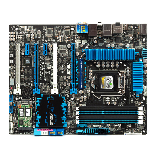
1.2.2 Motherboard layout Refer to 1.2.9 Internal connectors and 2.3.1 Rear I/O connection for more information about rear panel connectors and internal connectors. ASUS P8Z77-V PREMIUM Marvell 9230... -
Page 26: Layout Contents
Layout contents Connectors/Jumpers/Slots 1. ATX power connectors (24-pin EATXPWR, 8-pin EATX12V) 2. LGA1155 CPU socket 3. CPU, chassis, and power fan connectors (4-pin CPU_FAN, 4-pin CPU_OPT, 4-pin CHA_FAN1-4 ) 4. DDR3 DIMM slots 5. MemOK! button 6. TPM connector (20-1 pin TPM) 7. -
Page 27: Central Processing Unit (Cpu)
Contact your retailer immediately if the PnP cap is missing, or if you see any damage to the PnP cap/socket contacts/motherboard components. ASUS will shoulder the cost of repair only if the damage is shipment/ transit-related. -
Page 28: System Memory
1.2.4 System memory The motherboard comes with four Double Data Rate 3 (DDR3) Dual Inline Memory Modules (DIMM) slots. A DDR3 module is notched differently from a DDR or DDR2 module. DO NOT install a DDR or DDR2 memory module to the DDR3 slot. Recommended memory configurations 1-10 Chapter 1: Product introduction... -
Page 29: Memory Configurations
Always install the DIMMS with the same CAS Latency. For an optimum compatibility, we recommend that you install memory modules of the same version or data code (D/ C) from the same vendor. Check with the vendor to get the correct memory modules. ASUS P8Z77-V PREMIUM support site at http://support.microsoft. ®... - Page 30 P8Z77-V PREMIUM Motherboard Qualified Vendors Lists (QVL) DDR3 2800(O.C.) MHz capability Vendors Part No. G.skill F3-2800CL11Q- 16GBZHD * The 2800MHz memory modules above are supported on Intel however, the actual frequency support varied depending on the O.C. margin of the installed CPU.
- Page 31 O.C. margin of the installed CPU. ** Due to Intel 2nd generation processors' behavior, DDR3 2200 and above/2000/1800 MHz memory module runs ay DDR3 2133/1866/1600 MHz frequency as default. ASUS P8Z77-V PREMIUM Chip Chip...
- Page 32 DDR3 2133(O.C.) MHz capability Vendors Part No. A-DATA AX3U2133C2G9B(XMP) A-DATA AX3U2133GC2G9B(XMP) A-DATA AX3U2133GC4G9B(XMP) Apacer 78.BAGE4.AFD0C(XMP) CORSAIR CMT4GX3M2A2133C9(XMP) CORSAIR CMT4GX3M2B2133C9(Ver 7.1)(XMP) CORSAIR CMT4GX3M2B2133C9(XMP) G.SKILL F3-17000CL11Q2- 64GBZLD(XMP) G.SKILL F3-17000CL9Q- 16GBXLD(XMP) G.SKILL F3-17000CL9Q- 16GBZH(XMP) G.SKILL F3-17066CL9D- 8GBPID(XMP) G.SKILL F3-17066CL9Q- 16GBTDD(XMP) KINGSTON KHX2133C11D3K4/ 16GX(XMP) OCZ3XTEP2133C9LV4GK Patriot PVV34G2133C9K(XMP)
- Page 33 Patriot PX7312G2000ELK 12GB (XMP) (3x4GB) Silicon SP002GBLYU200S02 Power (XMP) Team TXD32048M2000C9 (XMP) Team TXD32048M2000C9-L (XMP) Transcend TX2000KLN-8GK (388375)(XMP) ASUS P8Z77-V PREMIUM Chip Chip No. Timing Voltage Brand 9-11-9-27 1.55~1.75 9-11-9-27 1.55~1.75 1.65 1.65 9-9-9-27 Hynix H5TQ2G83B 9-9-9-27 FRH9C 8-9-8-24 1.65...
- Page 34 DDR3 1866(O.C.) MHz capability Vendors Part No. A-DATA AX3U1866GC2G9B(XMP) A-DATA AX3U1866GC4G9B(XMP) CORSAIR CMT32GX3M4X1866C9 (Ver3.23)(XMP) CORSAIR CMZ32GX3M4X1866C 10(Ver3.23)(XMP) CORSAIR CMZ8GX3M2A1866C9 (XMP) Crucial BLE4G3D1869DE1XT0 .16FMD(XMP) G.SKILL F3-14900CL10Q2-64GB ZLD(XMP) G.SKILL F3-14900CL9D-8GBSR (XMP) G.SKILL F3-14900CL9Q-16GBXL (XMP) G.SKILL F3-14900CL9Q-16GBZL (XMP) G.SKILL F3-14900CL9Q-8GBFLD (XMP) Patriot PXD34G1866ELK(XMP) Patriot PXD38G1866ELK(XMP) Team...
- Page 35 8GB ( 2x (XMP) 4GB ) G.SKILL F3-12800CL7Q-16GBXH 16GB ( (XMP) 4x 4GB ) G.SKILL F3-12800CL8D- 8GB ( 8GBECO 2x4GB ) (XMP) ASUS P8Z77-V PREMIUM Chip Chip NO. Timing Brand A-DATA 3CCD-1509A A-DATA 3CCD-1509A 8-8-8-24 Asint 302G08-GG1C 9-9-9-27 Asint 302G08-GJ1C...
- Page 36 DDR3 1600 MHz capability Vendors Part No. G.SKILL F3-12800CL9D-8GBRL (XMP) G.SKILL F3-12800CL9D- 8GBSR2 (XMP) G.SKILL F3-12800CL9Q- 16GBXL (XMP) G.Skill F3-12800CL9Q- 16GBZL (XMP) GEIL GET316GB1600C9QC (XMP) GEIL GUP34GB1600C7DC (XMP) GoodRam GR1600D364L9/2G KINGMAX FLGE85F-C8KL9A (XMP) KINGMAX FLGF65F-C8KL9A (XMP) KINGSTON KHX1600C9D3K2/4GX (XMP) KINGSTON KHX1600C9D3K3/ 12GX (XMP)
- Page 37 Team TXD31024M1600C 8-D(XMP) Team TXD32048M1600C7- (XMP) Team TXD32048M1600H C8-D(XMP) Transcend JM1600KLN-8GK 8GB ( 2x 4GB ) Transcend TS256MLK64V6N Transcend TS512MLK64V6N ASUS P8Z77-V PREMIUM Chip Chip No. Timing Brand 6-8-6-24 8-8-8 23EY4587MB6H 23EY4587MB6H 8-8-8-24 8-9-8-24 8-9-8-24 ELPIDA J2108BDBG- GN-F Team T3D1288RT-16...
- Page 38 DDR3 1333 MHz capability Vendors Part No. Size A-DATA AD63I1B0823EV A-DATA AXDU1333GC2G9 (XMP) A-DATA AD63I1C1624EV A-DATA SU3U1333W8G9 (XMP) Apacer 78.A1GC6.9L1 Apacer 78.B1GDE.9L10C CORSAIR TW3X4G1333C9A 4GB ( 2x 2GB ) CORSAIR CMX8GX3M2A13 8GB ( 2x 33C9(XMP) 4GB ) G.SKILL F3-10600CL9D-4G 4GB ( 2x 2GB ) G.SKILL F3-10666CL9D-8G...
- Page 39 (574206) Transcend JM1333KLN-4G (583782 ) Transcend JM1333KLN-4G Transcend TS512MLK64V3N (574831) Transcend TS1GLK64V3H ACTICA ACT1GHU64B8F 1333S ACTICA ACT1GHU72C8G 1333S ASUS P8Z77-V PREMIUM Chip Brand Chip No. Kingmax KFC8FNMXF- BXX-15A Micron IFD77 D9LGK Kingston D1288JPNDPLD9U KINGSTON D1288JEMFPGD9U Elpida J2108ECSE-DJ-F MICRON D9PFJ SAMSUNG...
- Page 40 DDR3 1333 MHz capability Vendors Part No. ACTICA ACT2GHU64B8G 1333M ACTICA ACT2GHU64B8G 1333S ACTICA ACT2GHU72D8G 1333M ACTICA ACT2GHU72D8G 1333S ACTICA ACT4GHU64B8H1 333H ACTICA ACT4GHU72D8H 1333H AQ56M72E8BJH AQ12M72E8BKH BUFFALO D3U1333-1G BUFFALO D3U1333-2G BUFFALO D3U1333-4G EK Memory EKM324L28BP8-I Elixir M2F2G64CB88B 7N-CG Elixir M2F2G64CB88D7 N-CG Elixir...
- Page 41 Hyper DIMM support is subject to the physical characteristics of individual CPUs. Load the X.M.P. or D.O.C.P. settings in the BIOS for the hyper DIMM support. • Visit the ASUS website for the latest QVL. ASUS P8Z77-V PREMIUM Chip Brand Chip No.
-
Page 42: Expansion Slots
1.2.5 Expansion slots Unplug the power cord before adding or removing expansion cards. Failure to do so may cause you physical injury and damage motherboard components. Slot No. Slot Description PCIe 3.0/2.0 x16_1 slot PCIe 3.0/2.0 x16_2 slot PCIe 2.0 x1_1 slot PCIe 3.0/2.0 x16_3 slot PCIe 2.0 x1_2 slot PCIe 3.0/2.0 x16_4 slot... -
Page 43: Irq Assignments For This Motherboard
– Intel 82583 LAN shared PEX 8608 PCIE Bridge – ASMedia SATA – Controller Marvell 9230 Hardware shared RAID Controller ASUS P8Z77-V PREMIUM PCIe Express 3.0 operating mode 3-WAY SLI/ SLI/CrossFireX CrossFireX (dual VGA recommended) – – shared – –... -
Page 44: Onboard Buttons And Switches
The button also lights up when the system is plugged to a power source indicating that you should shut down the system and unplug the power cable before removing or installing any motherboard component. P8Z77-V PREMIUM Power on button Reset button Press the reset button to reboot the system. - Page 45 BIOS has been restored to its default settings. • We recommend that you download and update to the latest BIOS version from the ASUS website at www.asus.com after using the MemOK! function. ASUS P8Z77-V PREMIUM 1-27...
- Page 46 TPU switch Enable this switch to automatically optimize the system for fast, yet stable clock speeds. Enable this switch when the system is powered off. • The TPU LED (O2LED2) near the TPU switch lights up when the TPU switch is enabled.
- Page 47 You may change the EPU settings in the software application or BIOS setup program, and enable the EPU function at the same time. However, the system will use the last setting you have made. ASUS P8Z77-V PREMIUM OS environment, the EPU function will be ®...
- Page 48 Clear CMOS button Press this button to clear the BIOS setup information only when the systems hangs due to overclocking. P8Z77-V PREMIUM CLR_CMOS button Chapter 1: Product introduction 1-30...
-
Page 49: Jumpers
CPU permanently. We recommend you ro install the DIMMs with the voltage requirement below 1.65V. • The system may need a better cooling system (for example, a water cooling system) to work efficiently under high voltage settings. ASUS P8Z77-V PREMIUM OV_DRAM 1.2V - 1.92V 1.2V - 2.3V 1-31... -
Page 50: Onboard Leds
1.2.8 Onboard LEDs POST State LEDs The POST State LEDs provide the status of these key components during POST (Power-On-Self Test): CPU, memory modules, VGA card, and hard disk drive.s If an error is found, the critical component’s LED stays lit up until the problem is solved. TPU LED The TPU LED lights up when the TPU switch is enabled. - Page 51 The EPU LED lights up when the EPU switch is enabled. Q-Code LEDs The Q-Code LED design provides you with a 2-digit error code that displays the system status. Refer to the Q-Code table on the next page for details. ASUS P8Z77-V PREMIUM 1-33...
- Page 52 Q-Code table Code Description Not used Power on. Reset type detection (soft/hard). AP initialization before microcode loading System Agent initialization before microcode loading PCH initialization before microcode loading Microcode loading AP initialization after microcode loading System Agent initialization after microcode loading PCH initialization after microcode loading Cache initialization 0C –...
- Page 53 PCI host bridge initialization System Agent DXE initialization is started System Agent DXE SMM initialization is started 6B – 6F System Agent DXE initialization (System Agent module specific) PCH DXE initialization is started ASUS P8Z77-V PREMIUM (continued on the next page) 1-35...
- Page 54 Code Description PCH DXE SMM initialization is started PCH devices initialization 73 – 77 PCH DXE Initialization (PCH module specific) ACPI module initialization CSM initialization 7A – 7F Reserved for future AMI DXE codes Boot Device Selection (BDS) phase is started Driver connecting is started PCI Bus initialization is started PCI Bus Hot Plug Controller Initialization...
- Page 55 No Console Output Devices are found No Console Input Devices are found Invalid password Error loading Boot Option (LoadImage returned error) Boot Option is failed (StartImage returned error) Flash update is failed Reset protocol is not available ASUS P8Z77-V PREMIUM 1-37...
- Page 56 ACPI/ASL Checkpoints Code Description 0x01 System is entering S1 sleep state 0x02 System is entering S2 sleep state 0x03 System is entering S3 sleep state 0x04 System is entering S4 sleep state 0x05 System is entering S5 sleep state 0x10 System is waking up from the S1 sleep state 0x20 System is waking up from the S2 sleep state...
-
Page 57: Internal Connectors
ATA hard disk drives. The Serial ATA RAID feature is available only if you are using Windows XP SP3 or later versions. ® ASUS P8Z77-V PREMIUM Rapid Storage Technology through the onboard Intel XP Service Pack 3 or later versions before using Serial ®... - Page 58 Intel Z77 Serial ATA 3.0 Gb/s connectors (7-pin SATA3G_34/5 [blue]) ® These connectors connect to Serial ATA 3.0 Gb/s hard disk drives and optical disc drives via Serial ATA 3.0 Gb/s signal cables. If you installed Serial ATA hard disk drives, you can create a RAID 0, 1, 5, and 10 configuration with the Intel chipset.
- Page 59 91xx SATA Controller Driver. For Windows Controller Driver. • Connect one HDD and one SSD to Marvell performance of ASUS SSD Caching II. • The SATA6G_E12/E34 connectors are recommended for regular use. ASUS P8Z77-V PREMIUM XP Service Pack 3 or later versions before using Serial ATA ®...
- Page 60 USB 3.0 connector (20-1 pin USB3_12) This connector is for the additional USB 3.0 ports, and complies with the USB 3.0 specificaton that supports up to 480 MBps connection speed. If the USB 3.0 front panel cable is available from your system chassis, with this USB 3.0 connector, you can have a front panel USB 3.0 solution.
- Page 61 Never connect a 1394 cable to the USB connectors. Doing so will damage the motherboard! You can connect the front panel USB cable to the ASUS Q-Connector (USB, blue) first, and then install the Q-Connector (USB) to the USB connector onboard if your chassis supports front panel USB ports.
-
Page 62: Cpu, Chassis, And Power Fan Connectors
• The CPU_FAN connector supports the CPU fan of maximum 1A (12 W) fan power. • Only the CPU_FAN, CHA_FAN 1/2/3/4 connectors support the ASUS FAN Xpert 2 feature. 1-44 Chapter 1: Product introduction... - Page 63 • If you want to connect a high-definition or an AC’97 front panel audio module to this connector, set the Front Panel Type item in the BIOS setup to [HD] or [AC97]. ASUS P8Z77-V PREMIUM 1-45...
- Page 64 1000W power or above to ensure the system stability. • If you are uncertain about the minimum power supply requirement for your system, refer to the Recommended Power Supply Wattage Calculator at http://support.asus. com/PowerSupplyCalculator/PSCalculator.aspx?SLanguage=en-us for details. 1-46 Chapter 1: Product introduction...
-
Page 65: System Panel Connector
Pressing the power switch for more than four seconds while the system is ON turns the system OFF. • Reset button (2-pin RESET) This 2-pin connector is for the chassis-mounted reset button for system reboot without turning off the system power. ASUS P8Z77-V PREMIUM 1-47... - Page 66 TPM connector (20-1 pin TPM) This connector supports a Trusted Platform Module (TPM) system, which securely store keys, digital certificates, passwords and data. A TPM system also helps enhance network security, protect digital identities, and ensures platform integrity. MSATA 3.0 Gb/s connector (56-pin MSATA) This connector is for a single SATA 3.0 Gb/s solid-state drive (SSD).
-
Page 67: Chapter 2: Basic Installation
Motherboard installation The diagrams in this section are for reference only. The motherboard layout may vary with models, but the installation steps are the same for all models. Install the ASUS Q-Shield to the chassis rear I/O panel. ASUS P8Z77-V PREMIUM... - Page 68 Place the motherboard into the chassis, ensuring that its rear I/O ports are aligned to the chassis’ rear I/O panel. Chapter 2: Getting started...
- Page 69 Place nine screws into the holes indicated by circles to secure the motherboard to the chassis. DO NOT overtighten the screws! Doing so can damage the motherboard. ASUS P8Z77-V PREMIUM...
-
Page 70: Cpu Installation
2.1.2 CPU installation The LGA1156 CPU is not compatible with the LGA1155 socket. DO NOT install a LGA1156 CPU on the LGA1155 socket. Chapter 2: Getting started... -
Page 71: Cpu Heatsink And Fan Assembly Installation
2.1.3 CPU heatsink and fan assembly installation To install the CPU heatsink and fan assembly ASUS P8Z77-V PREMIUM Apply the Thermal Interface Material to the CPU heatsink and CPU before you install the heatsink and fan if necessary. - Page 72 To uninstall the CPU heatsink and fan assembly Chapter 2: Getting started...
-
Page 73: Dimm Installation
2.1.4 DIMM installation To remove a DIMM ASUS P8Z77-V PREMIUM... -
Page 74: Atx Power Connection
2.1.5 ATX Power connection Chapter 2: Getting started... -
Page 75: Sata Device Connection
2.1.6 SATA device connection ASUS P8Z77-V PREMIUM... -
Page 76: Front I/O Connector
2.1.7 Front I/O Connector To install ASUS Q-Connector To install USB 2.0 connector USB 2.0 To install USB 3.0 connector USB 3.0 2-10 To install front panel audio connector AAFP Chapter 2: Getting started... -
Page 77: Expansion Card Installation
2.1.8 Expansion Card installation To install PCIe x16 cards To install PCIe x1 cards ASUS P8Z77-V PREMIUM 2-11... -
Page 78: Wi-Fi Go! Card Installation
Disconnect the power supply unit from the motherboard before installing/uninstalling the Wireless and Bluetooth Module. Remove the screw from the ASUS Wi-Fi GO! card. Locate the Wi-Fi GO! card connector at the motherboard’s rear panel and connect the Wi-Fi GO! card to it. - Page 79 When you hear the clicking sound, the antenna connectors are properly inserted. Give a slight pull to determine that the installation is complete. Be sure to install the Bluetooth driver before installing the Wi-Fi GO! software. ASUS P8Z77-V PREMIUM IO Shield 2-13...
-
Page 80: Bios Update Utility
• Updating BIOS may have risks. If the BIOS program is damaged during the process and results to the system’s failure to boot up, please contact your local ASUS Service Center. 2-14... -
Page 81: Motherboard Rear And Audio Connections
Motherboard rear and audio connections 2.3.1 Rear I/O connection Rear panel connectors ASMedia USB 3.0 ports 1 and 2 support ASUS USB 3.0 Boost UASP Mode Optical S/PDIF Out port Intel LAN (RJ-45) port** ® Intel LAN (RJ-45) port** ®... - Page 82 * Bluetooth module LED indications Status Description No link Blue Linked Blinking Data activity ASUS Wi-Fi GO! card automatically sets itself to the country's available Wi-Fi channels, ** LAN ports LED indications Activity Link LED Status Description No link ORANGE Linked...
-
Page 83: Audio I/O Connections
Rear Speaker Out Gray – – 2.3.2 Audio I/O connections Audio I/O ports Connect to Headphone and Mic Connect to Stereo Speakers ASUS P8Z77-V PREMIUM 6-channel 8-channel Line In Line In Front Speaker Out Front Speaker Out Mic In Mic In... - Page 84 Connect to 2.1 channel Speakers Connect to 4.1 channel Speakers Connect to 5.1 channel Speakers Chapter 2: Getting started 2-18...
-
Page 85: Starting Up For The First Time
If you do not see anything within 30 seconds from the time you turned on the power, the system may have failed a power-on test. Check the jumper settings and connections or call your retailer for assistance. ASUS P8Z77-V PREMIUM 2-19... -
Page 86: Turning Off The Computer
BIOS Beep One short beep One continuous beep followed by two short beeps then a pause (repeated) One continuous beep followed by three short beeps One continuous beep followed by four short beeps At power on, hold down the <Delete> key to enter the BIOS Setup. Follow the instructions in Chapter 3. -
Page 87: Chapter 3: Bios Setup
BIOS setup Knowing BIOS The new ASUS UEFI BIOS is a Unified Extensible Interface that complies with UEFI architecture, offering a user-friendly interface that goes beyond the traditional keyboard- only BIOS controls to enable a more flexible and convenient mouse input. You can easily navigate the new UEFI BIOS with the same smoothness as your operating system. -
Page 88: Bios Setup Program
BIOS setup program Use the BIOS Setup to update the BIOS or configure its parameters. The BIOS screen include navigation keys and brief onscreen help to guide you in using the BIOS Setup program. Entering BIOS at startup To enter BIOS Setup at startup: •... -
Page 89: Ez Mode
The boot device options vary depending on the devices you installed to the system. The Boot Menu(F8) button is available only when the boot device is installed to the • system. ASUS P8Z77-V PREMIUM Selects the display language of the BIOS setup program Exits the BIOS setup program without saving... -
Page 90: Advanced Mode
3.2.2 Advanced Mode The Advanced Mode provides advanced options for experienced end-users to configure the BIOS settings. The figure below shows an example of the Advanced Mode. Refer to the following sections for the detailed configurations. To access the Advanced Mode, click Exit, then select Advanced Mode or press F7 hotkey. Back button Menu items UEFI BIOS Utility - Advanced Mode... -
Page 91: Configuration Fields
You cannot select an item that is not user-configurable. A configurable field is highlighted when selected. To change the value of a field, select it and press <Enter> to display a list of options. ASUS P8Z77-V PREMIUM... -
Page 92: Main Menu
Main menu The Main menu screen appears when you enter the Advanced Mode of the BIOS Setup program. The Main menu provides you an overview of the basic system information, and allows you to set the system date, time, language, and security settings. UEFI BIOS Utility - Advanced Mode Main Ai Tweaker... -
Page 93: Administrator Password
The User Password item on top of the screen shows the default Not Installed. After you set a password, this item shows Installed. To set a user password: Select the User Password item and press <Enter>. From the Create New Password box, key in a password, then press <Enter>. Confirm the password when prompted. ASUS P8Z77-V PREMIUM... -
Page 94: Ai Tweaker Menu
To change a user password: Select the User Password item and press <Enter>. From the Enter Current Password box, key in the current password, then press <Enter>. From the Create New Password box, key in a new password, then press <Enter>. Confirm the password when prompted. -
Page 95: Ai Overclock Tuner [Auto]
(X.M.P.) Technology, choose this item to set the profiles supported by your memory modules for optimizing the system performance. The following item appears only when you set the Ai Overclocking Tuner to [Manual]. ASUS MultiCore Enhancement [Enabled] [Enabled] Default set to [Enabled] for maximum performance under XMP/Manual/ User-defined memory frequency mode. - Page 96 2-Core Ratio Limit [Auto] Allows you to set the 2-Core Ratio Limit. [Auto] [Manual] 3-Core Ratio Limit [Auto] Allows you to set the 3-Core Ratio Limit. [Auto] [Manual] 4-Core Ratio Limit [Auto] Allows you to set the 4 Core Ratio Limit [Auto] [Manual] Internal PLL Overvoltage [Auto]...
-
Page 97: Dram Timing Control
Configuration options: [Auto] [48 DRAM Clock] – [511 DRAM Clock] DRAM Refresh Interval [Auto] Configuration options: [Auto] [48 DRAM Clock] – [511 DRAM Clock] DRAM WRITE Recovery Time [Auto] Configuration options: [Auto] [5 DRAM Clock] – [31 DRAM Clock] ASUS P8Z77-V PREMIUM 3-11... - Page 98 DRAM READ to PRE Time [Auto] Configuration options: [Auto] [4 DRAM Clock] – [15 DRAM Clock] DRAM FOUR ACT WIN Time [Auto] Configuration options: [Auto] [16 DRAM Clock] – [63 DRAM Clock] DRAM WRITE to READ Delay [Auto] Configuration options: [Auto] [4 DRAM Clock] – [15 DRAM Clock] DRAM CKE Minimum pulse width [Auto] Configuration options: [Auto] [4 DRAM Clock] –...
- Page 99 Channel B DIMM Control [Enable Bot...] Configuration options: [Enable Both DIMMS] [Disable DIMM0] [Disable DIMM1] [Disable Both DIMMS] DRAM Read Additional Swizzle [Auto] Configuration options: [Auto] [Enabled] [Disabled] DRAM Write Additional Swizzle [Auto] Configuration options: [Auto] [Enabled] [Disabled] ASUS P8Z77-V PREMIUM 3-13...
-
Page 100: Cpu Power Management
CPU Power Management The subitems in this menu allow you to set the CPU ratio and features. CPU Ratio [Auto] Allows you to manually adjust the maximum non-turbo CPU ratio. Use <+> and <-> keys to adjust the value. The valid value ranges vary according to your CPU model. Enhanced Intel SpeedStep Technology [Enabled] Allows you to enable or disable the Enhanced Intel [Disabled]... - Page 101 DO NOT remove the thermal module when switching to Extreme and Manual Mode. The thermal conditions should be monitored. Manual Adjustment [Fast] This item appears only when you set the CPU Power Phase Control item to [Manual Adjustment]. Configuration options: [Ultra Fast] [Fast] [Medium] [Regular] ASUS P8Z77-V PREMIUM 3-15...
-
Page 102: Cpu Current Capability [100%]
CPU Power Duty Control [T.Probe] DIGI + VRM Duty Control adjusts the current and thermal conditions of every component’s phase. [T. Probe] Select to maintain the VRM thermal balance. [Extreme] Select to maintain the current VRM balance. CPU Current Capability [100%] Allows you to configure the total power range, and extends the overclocking frequency range simultaneously. - Page 103 DRAM Power Phase Control [Auto] [Auto] Allows you to set the Auto mode. [Optimized] Allows you to set the ASUS optimized phase tuning profile. [Extreme] Allows you to set the full phase mode. DRAM Power Thermal Control [110] A higher temperature brings a wider DRAM power thermal range, and extends the overclocking tolerance to enlarge the O.C.
- Page 104 CPU Offset Voltage [Auto] This item appears only when you set the CPU Voltage item to [Offset Mode] and allows you to set the Offset voltage. The values range from 0.005V to 0.635V with a 0.005V interval. CPU Manual Voltage [Auto] This item appears only when you set the CPU Voltage item to [Manual Mode] and allows you to set a fixed CPU voltage.
-
Page 105: Dram Data Ref Voltage On Cha/B [Auto]
CPU Spread Spectrum [Auto] [Auto] Automatic configuration. [Disabled] Enhances the BCLK overclocking ability. [Enabled] Sets to [Enabled] for EMI control. BCLK Recovery Allows you to recover the BCLK parameters. Configuration options: [Auto] [Enabled] [Disabled] ASUS P8Z77-V PREMIUM 3-19... -
Page 106: Advanced Menu
Advanced menu The Advanced menu items allow you to change the settings for the CPU and other system devices. Be cautious when changing the settings of the Advanced menu items. Incorrect field values can cause the system to malfunction. UEFI BIOS Utility - Advanced Mode Ai Tweaker Main >... -
Page 107: Cpu Configuration
Configuration options: [All] [1] [2] [3] Limit CPUID Maximum [Disabled] [Enabled] Allows legacy operating systems to boot even without support for CPUs with extended CPUID functions. [Disabled] Disables this function. ASUS P8Z77-V PREMIUM Advanced Monitor Boot Adjust Non-Turbo Ratio Supported 3300 MHz... - Page 108 Execute Disable Bit [Enabled] [Enabled] Enables the No-Execution Page Protection Technology. [Disabled] Forces the XD feature flag to always return to zero (0). Intel Virtualization Technology [Disabled] ® [Enabled] Allows a hardware platform to run multiple operating systems separately and simultaneously, enabling one system to virtually function as several systems.
-
Page 109: Pch Configuration
Configuration options: [Enabled] [Disabled Entry After [Immediately] Allows you to set the wake-up time. Configuration options: [Immediately] [1 minute] [2 minutes] [5 minutes] [10 minutes] [15 minutes] [30 minutes] [1 hour] [2 hours] ASUS P8Z77-V PREMIUM Advanced Monitor Boot Enabled/Disabled the High Precision Event Timer. -
Page 110: Sata Configuration
Active Page Threshold Support [Enabled] The system automatically set itself to sleep when the partition size is not enough for Rapid Start Technology to work. Configuration options: [Enabled] [Disabled] Active Memory Threshold [0] Key in the value for the additional partition size for Rapid Start Technology to work. Ensure that the caching partition size is larger than the total memory size. -
Page 111: System Agent Configuration
> NB PCIe Configuration Memory Remap Feature [Enabled] Allows you to enable remapping the memory above 4GB. [Enabled] Enables the function. [Disabled] Disables this function. ASUS P8Z77-V PREMIUM Advanced Monitor Boot IvyBridge Enable or disable memory remap above Enabled Exit... -
Page 112: Graphics Configuration
Graphics Configuration Allows you to select a primary display from iGPU, and PCIe graphical devices. Primary Display [Auto] Allows you to select which of the iGPU/PCIE Graphics device should be the Primary Display. Configuration options: [Auto] [IGPU] [PCIE] iGPU Memory [64M] Allows you to select the amount of system memory allocated to DVMT 5.0 used by the iGPU. -
Page 113: Intel ® Thunderbolt
Increase the value for multi-function monitors. Reserved Memory [60] Increase the value for storage/graphic devices. Prefetachable memory [60] Increase the value for storage/graphic devices. Reserved I/O [24K] Increase the value for storage devices. ASUS P8Z77-V PREMIUM Advanced Monitor Boot Enabled Exit Tool... -
Page 114: Usb Configuration
3.5.6 USB Configuration The items in this menu allow you to change the USB-related features. UEFI BIOS Utility - Advanced Mode Main Ai Tweaker Back Advanced\ USB Configuration > USB Configuration USB Devices: 1 Keyboard, 1 Mouse, 2 Hubs Legacy USB Support Legacy USB3.0 Support Intel xHCI Mode EHCI Hand-off... -
Page 115: Onboard Devices Configuration
Sets the front panel audio connector (AAFP) mode to legacy AC’97 SPDIF Out Type [SPDIF] [SPDIF] Sets to [SPDIF] for SPDIF audio output. [HDMI] Sets to [HDMI] for HDMI audio output. ASUS P8Z77-V PREMIUM Advanced Monitor Boot Enabled/Disabled Bluetooth Controller Enabled... - Page 116 Bluetooth Controller [Enabled] [Enabled] Enables the onboard Bluetooth controller. [Disabled] Disables the onboard Bluetooth controller. Wi-Fi Controller [Enabled] [Enabled] Enables the onboard Wi-Fi controller. [Disabled] Disables the onboard Wi-Fi controller. Marvell Storage Controller [Enabled] Allows you to select the Marvell [Disabled] Disables the Marvell®...
-
Page 117: Apm
Disables the PCIE/PCI devices to generate a wake-on-LAN feature of the Intel/Realtek LAN device. [Enabled] Enables the PCIE/PCI devices to generate a wake-on-LAN feature of the Intel/Realtek LAN device. ASUS P8Z77-V PREMIUM Advanced Monitor Boot Disabled Allow BIOS to switch off some power... -
Page 118: Network Stack
Power On By RTC [Disabled] [Disabled] Disables RTC to generate a wake event. When set to [Enabled], the items RTC Alarm Date (Days) and Hour/ [Enabled] Minute/Second will become user-configurable with set values. 3.5.9 Network Stack UEFI BIOS Utility - Advanced Mode Ai Tweaker Main Back... -
Page 119: Monitor Menu
(RPM). If the fan is not connected to the motherboard, the field shows N/A. Select [Ignore] if you do not wish to display the detected speed. ASUS P8Z77-V PREMIUM Advanced Monitor Boot +73ºC / +163ºF... -
Page 120: Cpu Q-Fan Control [Enabled]
CPU Q-Fan Control [Enabled] [Disabled] Disables the CPU Q-Fan control feature. [Enabled] Enables the CPU Q-Fan control feature. CPU Fan Speed Low Limit [600 RPM] This item appears only when you enable the CPU Q-Fan Control feature and allows you to disable or set the CPU fan warning speed. -
Page 121: Cpu Voltage, 3.3V Voltage, 5V Voltage, 12V Voltage
The onboard hardware monitor automatically detects the voltage output through the onboard voltage regulators. Select Ignore if you do not want to detect this item. Anti Surge Support [Enabled] This item allows you to enable or disable the Anti Surge function. Configuration options: [Disabled] [Enabled] ASUS P8Z77-V PREMIUM 3-35... -
Page 122: Boot Menu
Full Screen Logo [Enabled] [Enabled] Enables the full screen logo display feature. [Disabled] Disables the full screen logo display feature. Set this item to [Enabled] to use the ASUS MyLogo 2™ feature. Wait For ‘F1’ If Error [Enabled] [Disabled] Disables this function. [Enabled] The system waits for the <F1>... -
Page 123: Boot Option Priorities
Press <F5> when ASUS Logo appears. • Press <F8> after POST. • To select the boot device during system startup, press <F8> when ASUS Logo appears. Boot Override These items displays the available devices. The number of device items that appears on the screen depends on the number of devices installed in the system. -
Page 124: Tools Menu
3.8.1 ASUS EZ Flash 2 Utility Allows you to run ASUS EZ Flash 2. When you press <Enter>, a confirmation message appears. Use the left/right arrow key to select between [Yes] or [No], then press <Enter> to confirm your choice. -
Page 125: Asus Spd Information
ASUS SPD Information Allows you to view the DRAM SPD information. UEFI BIOS Utility - Advanced Mode Main Ai Tweaker Back Tool\ ASUS SPD Information > DIMM Slot # Manufacturer Module Size Maximum Bandwidth Part Number Serial Number Product Week/Year SPD Ext. -
Page 126: Exit Menu
Load Optimized Defaults Save Changes & Reset Discard Changes & Exit ASUS EZ Mode Launch EFI Shell from filesystem device Load Optimized Defaults This option allows you to load the default values for each of the parameters on the Setup menus. -
Page 127: Updating Bios
BIOS in the future. Copy the original motherboard BIOS using the ASUS Update or BIOS Updater utilities. 3.10.1 ASUS Update The ASUS Update is a utility that allows you to manage, save, and update the motherboard BIOS in Windows environment. ®... - Page 128 Launching ASUS Update To launch ASUS Update, click Update > ASUS Update on the AI Suite II main menu bar. Quit all Windows® applications before you update the BIOS using this utility. Updating the BIOS through the Internet To update the BIOS through the Internet:...
- Page 129 The screenshots in this section are for reference only. The actual BIOS information vary by models. • Refer to the software manual in the support DVD or visit the ASUS website at www.asus.com for detailed software configuration. ASUS P8Z77-V PREMIUM...
-
Page 130: Asus Ez Flash 2
3.10.2 ASUS EZ Flash 2 ASUS EZ Flash 2 allows you to update the BIOS without having to use a bootable floppy disk or an OS-based utility. Before you start using this utility, download the latest BIOS from the ASUS website at www.asus.com. -
Page 131: Asus Crashfree Bios 3
The BIOS file in the motherboard support DVD may be older than the BIOS file published on the ASUS official website. If you want to use the newer BIOS file, download the file at support.asus.com and save it to a USB flash drive. -
Page 132: Asus Bios Updater
3.10.4 ASUS BIOS Updater The ASUS BIOS Updater allows you to update the BIOS in DOS environment. This utility also allows you to copy the current BIOS file that you can use as a backup when the BIOS fails or gets corrupted during the updating process. - Page 133 Press <Tab> to switch between screen fields and use the <Up/Down/Home/End> keys to select the BIOS file and press <Enter>. BIOS Updater checks the selected BIOS file and prompts you to confirm BIOS update. Are you sure to update BIOS? ASUS P8Z77-V PREMIUM Update ROM BOARD: UNKNOWN...
- Page 134 Select Yes and press <Enter>. When BIOS update is done, press <ESC> to exit BIOS Updater. Restart your computer. DO NOT shut down or reset the system while updating the BIOS to prevent system boot failure! • For BIOS Updater version 1.04 or later, the utility automatically exits to the DOS prompt after updating BIOS.
-
Page 135: Chapter 4: Software Support
Support DVD information The contents of the support DVD are subject to change at any time without notice. Visit the ASUS website at www.asus.com for updates. 4.2.1 Running the support DVD Place the support DVD into the optical drive. -
Page 136: Obtaining The Software Manuals
The software manual files are in Portable Document Format (PDF). Install the Adobe® Acrobat® Reader from the Utilities menu before opening the files. Click the Manual tab. Click ASUS Motherboard Utility Guide from the manual list on the left. -
Page 137: Software Information
4.3.1 AI Suite II AI Suite II is an all-in-one interface that integrates several ASUS utilities and allows users to launch and operate these utilities simultaneously. Installing AI Suite II To install AI Suite II on your computer: Place the support DVD to the optical drive. -
Page 138: Turbov Evo
To launch AI Suite II, click Tool > TurboV EVO on the AI Suite II main menu bar.. Refer to the software manual in the support DVD or visit the ASUS website at www.asus. com for detailed software configuration. -
Page 139: Using Advanced Mode
Using Advanced Mode Click on the Advanced Mode tab to adjust the advanced voltage settings. Advanced mode Target values Current values Click to restore all startup settings ASUS P8Z77-V PREMIUM Voltage Adjustment bars Undoes all the changes Applies all the changes immediately... - Page 140 CPU Ratio Allows you to manually adjust the CPU ratio. The first time you use CPU Ratio, go to AI Tweaker > CPU Power Management in • BIOS and set the Turbo Ratio item to [Maximum Turbo Ratio setting in OS]. •...
-
Page 141: Auto Tuning
Current values Click to restore all startup settings Auto Tuning ASUS TurboV EVO provides you with these two auto-tuning modes for the most flexible auto- tuning options. • The overclocking result varies with the CPU model and the system configuration. - Page 142 After the system restarts, a message appears indicating that auto-tuning is successful. Click OK to exit. Using Extreme Tuning Click Auto Tuning tab > Extreme. Read the warning messages and click OK to start the auto- overclocking process. TurboV automatically overclocks the CPU and memory, and restarts the system.
-
Page 143: Digi+ Power Control
4.3.3 DIGI+ Power Control ASUS DIGI+ Power Control allows you to adjust VRM voltage and frequency modulation to enhance reliability and stability. It also provides the highest power efficiency, generating less heat to prolong the component lifespan and minimize power loss. -
Page 144: Cpu Power
Smart CPU Power Level - 35W CPU power usage is limited to 35W to achieve the best digital power saving mode. OC Now! Adjusts the CPU ratio in TurboV EVO. Default (Smart DIGI+ Setting) Sets your CPU/iGPU/DRAM power to default settings. Default (Smart CPU Power Level) Sets your power consumption to CPU default setting. - Page 145 The DIGI+ Power controller provides a faster and precise power response rate for CPU. Apply a higher value for an extreme overclocking. CPU Power Duty Control CPU Power Duty Control adjusts the current of every VRM phase and the thermal conditions of every phase component. ASUS P8Z77-V PREMIUM 4-11...
- Page 146 OC Range. DRAM Power Phase Control Select Extreme for full phase mode to increase system performance or select Optimized for ASUS optimized phase tuning profile to increase DRAM power efficiency. DRAM Power Thermal Control A higher temperature brings a wider DRAM power thermal range, and extends the overclocking tolerance to enlarge overclocking potential.
-
Page 147: Launching Epu
*Select From the Last Reset to show the total CO2 that has been reduced since you click the Clear button • Refer to the software manual in the support DVD or visit the ASUS website at www. asus.com for detailed software configuration. ASUS P8Z77-V PREMIUM... -
Page 148: Usb 3.0 Boost
Turbo mode or UASP mode (if UASP is supported by the USB 3.0 device). You can manually switch the USB 3.0 mode back to Normal mode at any time. • Refer to the software manual in the support DVD or visit the ASUS website at www. asus.com for detailed software configuration. •... -
Page 149: Usb Bios Flashback Wizard
In the Download Setting field, tick Schedule (days) and select the number of days for your download schedule. Click Apply to save the BIOS download schedule. Click Cancel to cancel the changes made. ASUS P8Z77-V PREMIUM Current BIOS information Cancels all the changes... - Page 150 Downloading the updated BIOS Click Check for New BIOS Update to check for the latest BIOS version. Wait for the system to check the latest BIOS firmware. After the utility detects a new BIOS firmware, save the BIOS firmware by clicking from the Save to field, select the USB flashdrive, and click Download.
-
Page 151: Asus Ssd Caching Ii
It combines multiple SSDs’ performance and hard-drive capacity to boost the system’s overall performance. Launching ASUS SSD Caching II To launch ASUS SSD Caching, click Tool > ASUS SSD Caching II on the AI Suite II main menu bar. Tick one or... - Page 152 To cancel caching, click • During initialization, you can proceed with doing any system operations. You can check the caching status later or wait for a pop-up message notifying that initialization is completed. • For regular usage, the SATA6G_E12/E34 connectors are recommended for data drives.
-
Page 153: Ai Charger
** Actual charging speeds may vary depending on the charging rate and specifications of your USB device. • To ensure normal charging function, disconnect and reconnect your USB device every time you enable or disable Ai Charger+. ASUS P8Z77-V PREMIUM 4-19... -
Page 154: Probe Ii
Click Monitor > Sensor on the AI Suite II main menu bar and the system status will • appear on the right panel. • Refer to the software manual in the support DVD or visit the ASUS website at www.asus.com for detailed software configuration. 4-20 Loads the default... -
Page 155: Sensor Recorder
To launch Sensor Recorder, click Tool > Sensor Recorder on the AI Suite II main menu bar. Using Sensor Recorder Click on Voltage/ Temperature/ Fan Speed tabs for the status you want to monitor. Colored lines will automatically appear on the diagram to indicate the immediate changes in the system status. ASUS P8Z77-V PREMIUM 4-21... - Page 156 Using History Record Click the History Record tab and adjust the settings on the left for Record Interval and Record Duration according to need. Click Start Recording to start measuring and recording each sensor. To stop recording, click Recording again. To track the recorded contents, set Type/ Date/ Select display items to display the history details.
-
Page 157: Asus Update
Windows environment. ® Launching ASUS Update To launch ASUS Update, click Update > ASUS Update on the AI Suite II main menu bar. Using ASUS Update Select any of these options to update the BIOS: • Update BIOS from Internet Allows you to download the latest BIOS version from the ASUS website at www.asus. -
Page 158: Mylogo2
MyLogo2 allows you to customize the boot logo, which is the image that appears on the screen during the Power On Self Tests (POST). Launching ASUS Update To launch MyLogo2, click Update > MyLogo on the AI Suite II main menu bar. -
Page 159: Audio Configurations
® find the Realtek HD Audio Manager icon on the taskbar. ® Double-click on the icon to display the Realtek HD Audio Manager. ASUS P8Z77-V PREMIUM proprietary UAJ ® Audio Driver from the support DVD that ® Realtek HD Audio Manager ®... - Page 160 Control settings window Information button • Refer to the software manual in the support DVD or visit the ASUS website at www. asus.com for detailed software configuration. • Due to Intel driver is only supported by Windows® 7™/Windows •...
-
Page 161: Chapter 5: Raid Support
With the RAID 10 configuration you get all the benefits of both RAID 0 and RAID 1 configurations. Use four new hard disk drives or use an existing drive and three new drives for this setup. ASUS P8Z77-V PREMIUM XP Service Pack 3 or later versions before using Serial ®... -
Page 162: Installing Serial Ata Hard Disks
5.1.2 Installing Serial ATA hard disks The motherboard supports Serial ATA hard disk drives. For optimal performance, install identical drives of the same model and capacity when creating a disk array. To install the SATA hard disks for a RAID configuration: Install the SATA hard disks into the drive bays. -
Page 163: Intel ® Rapid Storage Technology Option Rom Utility
The RAID BIOS setup screens shown in this section are for reference only and may not exactly match the items on your screen. The utility supports maximum four hard disk drives for RAID configuration. ASUS P8Z77-V PREMIUM All Rights Reserved. [ MAIN MENU ] 4. -
Page 164: Creating A Raid Set
Creating a RAID set To create a RAID set: From the utility main menu, select 1. Create RAID Volume and press <Enter>. The following screen appears: Intel(R) Rapid Storage Technology - Option ROM - v10.5.1.1070 Copyright(C) 2003-10 Intel Corporation. Enter a unique volume name that has no special characters and is 16 characters or less. - Page 165 WARNING: ALL DATA ON SELECTED DISKS WILL BE LOST. Are you sure you want to create this volume? (Y/N): Press <Y> to create the RAID volume and return to the main menu, or <N> to go back to the CREATE VOLUME menu. ASUS P8Z77-V PREMIUM...
- Page 166 Deleting a RAID set Be cautious when deleting a RAID set. You will lose all data on the hard disk drives when you delete a RAID set. To delete a RAID set: From the utility main menu, select 2. Delete RAID Volume and press <Enter>. The following screen appears: Name Level...
-
Page 167: Marvell Raid Utility
└ PD 0: ST3160812AS ├ └ PD 8: ST3160812AS ▶ Help Marvell RAID on chip controller. ENTER: Operation F10: Exit/Save ASUS P8Z77-V PREMIUM [ CONFIRM EXIT ] Information Vendor ID 1B4B Device ID 9130 Revision ID BIOS Version 1.0.0.1028 Firmware Version: 2.2.0.1105... -
Page 168: Create A Raid Array
Create a RAID Array Move the selection bar to HBA 0: Marvell 0 and press <Enter>. Select Configuration Wizard and press <Enter>. Marvell BIOS Setup (c) 2009 Marvell Technology Group Ltd. Configure->Select free disks HBA 0: Marvell 0 Virtual Disks ├ └ Free Physical Disks ├... - Page 169 ├ PD 0: ST3160812AS │ └ PD 8: ST3160812AS │ └ Free Physical Disks ▶ Help Marvell RAID on chip controller. ENTER: Operation F10: Exit/Save ASUS P8Z77-V PREMIUM Information Vendor ID 1B4B Device ID 9130 Revision ID BIOS Version 1.0.0.1028 Firmware Version: 2.2.0.1105 PCIe Speed Rate : 5.0Gbps...
-
Page 170: Delete An Existing Raid Array
Press <F10>. The following warning message appears: Exit Do you want to exit from Marvell BIOS Setup? Press <Y> to save the RAID setting and exit the Marvell RAID utility. Delete an existing RAID Array Select the RAID array to delete and press <Enter>. Select Delete and press <Enter>. Marvell BIOS Setup (c) 2009 Marvell Technology Group Ltd. -
Page 171: Creating A Raid Driver Disk
Go to the Make Disk menu, and then click Intel AHCI/RAID Driver Disk to create a RAID driver disk. Select USB floppy disk drive as the destination disk. Follow the succeeding screen instructions to complete the process. Write-protect the floppy disk to avoid a computer virus infection. ASUS P8Z77-V PREMIUM operating system ® ® ®... -
Page 172: Installing The Raid Driver During Windows ® Os Installation
5.2.3 Installing the RAID driver during Windows installation To install the RAID driver in Windows During the OS installation, the system prompts you to press the <F6> key to install third-party SCSI or RAID driver. Press <F6>, and then insert the floppy disk with RAID driver into the USB floppy disk drive. -
Page 173: Using A Usb Floppy Disk Drive
Product ID (PID) are displayed. Browse the contents of the RAID driver disk to locate the file txtsetup.oem. Double-click the file. A window appears, allowing you to select the program for opening the oem file. ASUS P8Z77-V PREMIUM 5-13... - Page 174 Use Notepad to open the file. Find the [HardwareIds.scsi.iaAHCI_DesktopWorkstationServer] and [HardwareIds.scsi.iaStor_DesktopWorkstationServer] sections in the txtsetup.oem file. Type the following line to the bottom of the two sections: id = “USB\VID_xxxx&PID_xxxx”, “usbstor” [HardwareIds.scsi.iaAHCI_ DesktopWorkstationServer] id= “PCI\VEN_8086&DEV_1C02&CC_0106”,”iaStor” id= “USB\VID_03EE&PID_6901”, “usbstor” [HardwareIds.scsi.iaStor_ DesktopWorkstationServer] id= “PCI\VEN_8086&DEV_2822&CC_0104”,”iaStor”...
-
Page 175: Chapter 6: Multiple Gpu Support
For Windows 7, go to Control Panel > Programs and Features. Select your current graphics card driver/s. For Windows XP, select Add/Remove. For Windows 7, select Uninstall. Turn off your computer. ASUS P8Z77-V PREMIUM CrossFireX™ technology that allows you to install ®... -
Page 176: Installing Two Crossfirex™ Graphics Cards
6.1.3 Installing two CrossFireX™ graphics cards The following pictures are for reference only. The graphics cards and the motherboard layout may vary with models, but the installation steps remain the same. Prepare two CrossFireX-ready graphics cards. Insert the two graphics card into the PCIEX16 slots. -
Page 177: Installing Three Crossfirex™ Graphics Cards
Ensure that the connectors are firmly in place. Connect three independent auxiliary power sources from the power supply to the three graphics cards separately. Connect a VGA or a DVI cable to the graphics card. ASUS P8Z77-V PREMIUM... -
Page 178: Installing Four Crossfirex™ Graphics Cards
6.1.5 Installing four CrossFireX™ graphics cards Prepare four CrossFireX-ready graphics cards. Insert the four graphics card into the PCIEX16 slots. Refer to Chapter 1 in this user manual for the locations of the PCIEX16 slots recommended for multi-graphics card installation. Ensure that the cards are properly seated on the slots. -
Page 179: Installing The Device Drivers
Launching the AMD Catalyst Control Center To launch the AMD Catalyst Control Center: Right-click on the Windows Catalyst Control Center. Click Catalyst Control Center to configure the displays and settings of your AMD graphic cards. ASUS P8Z77-V PREMIUM CrossFireX™ technology ® desktop and select ®... - Page 180 Enabling Dual CrossFireX technology In the Catalyst Control Center window, click Performance > AMD CrossFireX Select Enable CrossFireX Select a GPU combination from the drop-down list. Click Apply to save and activate the GPU settings made. Chapter 6: Multiple GPU support...
-
Page 181: Nvidia ® Sli™ Technology
Chapter 2 in this user manual for the locations of the PCIEX16 slots recommended for multi-graphics card installation. Ensure that the cards are properly seated on the slots. ASUS P8Z77-V PREMIUM SLI™ (Scalable Link Interface) technology that ® ®... -
Page 182: Installing Three Sli-Ready Graphics Cards
Align and firmly insert the SLI bridge connector to the goldfingers on each graphics card. Ensure that the connector is firmly in place. Connect two independent auxiliary power sources from the power supply to the two graphics cards separately. Connect a VGA or a DVI cable to the graphics card. -
Page 183: Installing Four Sli-Ready Graphics Cards
Refer to the documentation that came with your graphics card package to install the device drivers. Ensure that your PCI Express graphics card driver supports the NVIDIA Download the latest driver from the NVIDIA website (www.nvidia.com). ASUS P8Z77-V PREMIUM 4-Way SLI bridge SLI™ technology. ®... -
Page 184: Enabling The Nvidia ® Sli™ Technology
6.2.6 Enabling the NVIDIA After installing your graphics cards and the device drivers, enable the SLI feature in NVIDIA® Control Panel under the Windows® 7 operating system. Launching the NVIDIA Control Panel You can launch the NVIDIA Control Panel by the following two methods. Right click on the empty space of the Windows Panel. - Page 185 Enabling SLI settings From the NVIDIA Control Panel window, select Configure SLI, Surround, PhysX. In the Quad-SLI enabled, click Maximize 3D Performance SLI to set the display for viewing SLI rendered content. When done, click Apply. ASUS P8Z77-V PREMIUM 6-11...
-
Page 186: Lucidlogix Virtu Mvp
Installing LucidLogix Virtu MVP To install LucidLogix Virtu MVP: Insert the support DVD in the optical drive. The ASUS Support Wizard appears if your computer has enabled the Autorun feature. Click the Utilites tab, then click LucidLogix Virtu MVP Software. -
Page 187: Setting Up Your Display
3D gaming performance. i-Mode (VGA output from motherboard) The motherboard’s IO ports and discrete graphic card is for reference only and may vary in different models. ASUS P8Z77-V PREMIUM d-Mode (VGA output from discrete graphics card) 6-13... -
Page 188: Configuring Lucidlogix Virtu Mvp
6.3.3 Configuring LucidLogix Virtu MVP Launch the Virtu MVP Control Panel to allow you to configure the main features, adjust the performance settings and select applications for graphical virtualization. To open the control panel, right-click LucidLogix Virtu MVP icon in the notification area and select Open Virtu MVP Control Panel. - Page 189 Performance Allows you to turn ON/OFF the Hyperformance or Virtual Vsync function. ® Click to turn Hyperformance® ON or OFF Click to turn Virtual Vsync ON or OFF ASUS P8Z77-V PREMIUM 6-15...
- Page 190 Applications Allows you to select applications for graphic virtualization. Click to select a program to run by discrete card, iGPU, or Hyperformance Click to add, edit, or remove programs See the descriptions of these columns below: • D column allows you to run applications with the discrete graphic card. Select D to enable 3D graphical performance for that application.
-
Page 191: Chapter 7: Intel ® Technologies
Rapid Start Technology, DRAM size smaller than 8GB is ® required. Ensure to enable the acceleration of Intel the partition for the Intel ASUS P8Z77-V PREMIUM 2012 Desktop responsiveness, your ® Smart Response Technology before creating ® Rapid Start Technology. - Page 192 SSD Capacity Requirements SSD Partition Capacity Requirements Intel Rapid Start ® Intel Smart Response ® Intel Smart Response ® Intel Rapid Start ® Intel Smart Response, ® Intel Rapid Start, ® Intel Smart Connect ® • The SSD used for Intel creating RAID.
-
Page 193: Intel ® Smart Response Technology
SSD and HDD at the same time. Maximized mode: WRITE BACK, write to SSD and write back to HDD in a later time. ASUS P8Z77-V PREMIUM Smart Response Technology, setting the SATA Mode BIOS item to Rapid Storage Technology Driver software. ®... -
Page 194: Intel ® Rapid Start Technology
Select Disable Acceleration to disable this function, and select Change Mode to switch acceleration mode to Enhanced/ Maximized. • To enable Intel and an HDD, and only one SSD can be assigned for caching. If you want to restore the OS, go to BIOS Option ROM > Acceleration Options •... - Page 195 Go to Start > Control Panel > System and Security > System, and check the DRAM size information. The unallocated volume is allocated to the selected disk. ASUS P8Z77-V PREMIUM Smart Response to allow enough capacity for the ® ®...
- Page 196 To launch the disk partitioning tool, click Start > Programs > Accessories > Command Prompt tool. Type diskpart and press <Enter>. In the diskpart prompt, type list disk after DISKPART, and press <Enter>. Select the disk with the unallocated volume by typing select disk x (x = disk number), and press <Enter>.
- Page 197 Rapid Start Technology. ® Click the Show hidden icons arrow from the right side of the taskbar, and click Intel Manager icon. ASUS P8Z77-V PREMIUM Rapid Start Technology under the OS ® Rapid Start Manager to enable or disable the ®...
-
Page 198: Recovering The Partition
Tick On in the Status field to enable the function, and click Save. Click to enable or disable battery saving mode. This function only applies to notebooks. Click to enable or disable the timer. When enabled, move the scroll bar to the desired time. When the system is idle for more than the time period you set, the system automatically goes into the Intel Rapid Start mode. - Page 199 In the desktop, click Start, right-click Computer, and click Manage. In the Computer Management window, click Disk Management, right click the shrinked new volume, and select Extend Volume. As the Extend Volume Wizard appears, click Next. ASUS P8Z77-V PREMIUM...
-
Page 200: Intel ® Smart Connect Technology
Click Next after selecting the default selected disk. Extend volume setup is completed. Click Finish to recover the Intel Rapid Start Technology partition. Reboot the system after deleting the partition. Go to Start > Control Panel > Programs > Programs and Features to remove the Intel ®... -
Page 201: Using The Intel Smart Connect Technology
Disable Updating. Clicking this button automatically disables the configuration in the Advanced tab. To reset to defaults, click Reset All to Defaults. ASUS P8Z77-V PREMIUM Smart Connect ® Smart Connect Technology. ® Click to view version information and help topics... - Page 202 In the Advanced tab, set up the schedule during low power usage time period for power saving. This setting only applies to the assigned time period. In the Help tab, click About to view the feature’s version. Click Topics to learn more about the Intel Smart Connect Technology and its configuration.
-
Page 203: Appendices
The use of shielded cables for connection of the monitor to the graphics card is required to assure compliance with FCC regulations. Changes or modifications to this unit not expressly approved by the party responsible for compliance could void the user’s authority to operate this equipment. ASUS P8Z77-V PREMIUM... -
Page 204: Canadian Department Of Communications Statement
IC: Canadian Compliance Statement Complies with the Canadian ICES-003 Class B specifications. This device complies with RSS 210 of Industry Canada. This Class B device meets all the requirements of the Canadian interference-causing equipment regulations. This device complies with Industry Canada license exempt RSS standard(s). Operation is subject to the following two conditions: (1) this device may not cause interference, and (2) this device must accept any interference, including interference that may cause undesired operation of the device. -
Page 205: Rf Equipment Notices
ASUS Recycling/Takeback Services ASUS recycling and takeback programs come from our commitment to the highest standards for protecting our environment. We believe in providing solutions for you to be able to responsibly recycle our products, batteries, other components as well as the packaging materials. -
Page 206: Bluetooth Industry Canada Statement
Bluetooth Industry Canada Statement This Class B device meets all requirements of the Canadian interference-causing equipment regulations. Cet appareil numérique de la Class B respecte toutes les exigences du Règlement sur le matériel brouilleur du Canada. BSMI: Taiwan Wireless Statement Japan RF Equipment Statement KC (RF Equipment) Appendices... -
Page 207: Asus Contact Information
ASUS COMPUTER INTERNATIONAL (America) Address Telephone Web site Technical Support Telephone Support fax Online support ASUS COMPUTER GmbH (Germany and Austria) Address Web site Online contact Technical Support Telephone Support Fax Online support * EUR 0.14/minute from a German fixed landline; EUR 0.42/minute from a mobile phone. - Page 208 Appendices...
Need help?
Do you have a question about the P8Z77-V PREMIUM and is the answer not in the manual?
Questions and answers