Table of Contents
Advertisement
Quick Links
Advertisement
Table of Contents

Subscribe to Our Youtube Channel
Related Manuals for Asus Z9NR-D12


Summary of Contents for Asus Z9NR-D12
- Page 1 Z9NR-D12...
- Page 2 Product warranty or service will not be extended if: (1) the product is repaired, modified or altered, unless such repair, modification of alteration is authorized in writing by ASUS; or (2) the serial number of the product is defaced or missing.
-
Page 3: Table Of Contents
About this guide ..................x How this guide is organized ...............x Where to find more information ............x Conventions used in this guide ............xi Typography ..................xi Z9NR-D12 specifications summary ............xii Chapter 1: Product introduction Welcome! ..................1-3 Package contents ................. 1-3 Serial number label .............. -
Page 4: Contents
2.5.8 PCI Express x4 slot (x1 link) ......... 2-16 2.5.9 PIKE slots ..............2-17 2.5.10 Installing an ASUS PIKE RAID card ......2-18 2.5.11 Installing ASMB6 management board ......2-19 Onboard LEDs ................2-20 Jumpers ..................2-25 Connectors ................. 2-29 2.8.1... - Page 5 Contents 4.2.6 General help ..............4-9 4.2.7 Configuration fields ............4-9 4.2.8 Pop-up window ............... 4-9 4.2.9 Scroll bar ................. 4-9 Main menu .................. 4-10 4.3.1 System Date [Day xx/xx/xxxx] ........4-10 4.3.2 System Time [xx:xx:xx] ..........4-10 Advanced menu ................. 4-11 4.4.1 CPU Configuration ............4-11 4.4.2...
- Page 6 Contents Chapter 5: RAID configuration Setting up RAID ................5-3 5.1.1 RAID definitions .............. 5-3 5.1.2 Installing hard disk drives ..........5-4 5.1.3 Setting the RAID item in BIOS ........5-4 5.1.4 RAID configuration utilities ..........5-4 LSI Software RAID Configuration Utility ........5-5 5.2.1 Creating a RAID set ............
- Page 7 6.8.1 Running the support DVD ..........6-33 6.8.2 Drivers menu ..............6-33 6.8.3 Utilities menu ..............6-34 6.8.4 Make disk menu ............6-34 6.8.5 Contact information ............6-34 Appendix: Reference information Z9NR-D12 block diagram .............A-3 ASUS contact information ................1...
-
Page 8: Notices
Canadian Department of Communications. This class B digital apparatus complies with Canadian ICES-003. REACH Complying with the REACH (Registration, Evaluation, Authorization, and Restriction of Chemicals) regulatory framework, we publish the chemical substances in our products at ASUS REACH website at http://csr.asus.com/english/REACH.htm. viii... -
Page 9: Safety Information
Safety information Electrical safety • To prevent electrical shock hazard, disconnect the power cable from the electrical outlet before relocating the system. • When adding or removing devices to or from the system, ensure that the power cables for the devices are unplugged before the signal cables are connected. -
Page 10: About This Guide
Refer to the following sources for additional information and for product and software updates. ASUS websites The ASUS website provides updated information on ASUS hardware and software products. Refer to the ASUS contact information. Optional documentation Your product package may include optional documentation, such as warranty flyers, that may have been added by your dealer. -
Page 11: Conventions Used In This Guide
Conventions used in this guide To make sure that you perform certain tasks properly, take note of the following symbols used throughout this manual. DANGER/WARNING: Information to prevent injury to yourself when trying to complete a task. CAUTION: Information to prevent damage to the components when trying to complete a task. -
Page 12: Z9Nr-D12 Specifications Summary
SAS Controller Optional kits: ASUS PIKE 2008 8-port SAS 6G RAID card ASUS PIKE 2008/IMR 8-port SAS 6G RAID card ASUS PIKE 2108 8-port SAS 6G HW RAID card Networking 4 * Intel 82574L + 1 Management Port Graphic ASPEED AST2300 + 16MB ®... - Page 13 Environment °C °C Operation temperature: 10 – 35 °C °C Non operation temperature: -40 – 70 Non operation humidity: 20% – 90% (Non condensing) *Refer to ASUS Server AVL for latest update. **Specifications are subject to change without notice. xiii...
-
Page 15: Chapter 1: Product Introduction
This chapter describes the motherboard features and the new technologies it supports. Product introduction... - Page 16 Chapter summary Welcome! ..................1-3 Package contents ................. 1-3 Serial number label ..............1-4 Special features ................1-4 ASUS Z9NR-D12...
-
Page 17: Welcome
® The motherboard delivers a host of new features and latest technologies, making it another standout in the long line of ASUS quality motherboards! Before you start installing the motherboard, and hardware devices on it, check the items in your package with the list below. -
Page 18: Serial Number Label
Before requesting support from the ASUS Technical Support team, you must take note of the motherboard's serial number containing 12 characters xxS2xxxxxxxx shown as the figure below. With the correct serial number of the product, ASUS Technical Support team members can then offer a quicker and satisfying solution to your problems. - Page 19 DDR3 memory support The Z9NR-D12 supports DDR3 memory that features data transfer rates of 1600/1333/1066 MHz to meet the higher bandwidth requirements of server and workstation applications. The 3-channel DDR3 architecture boosts system performance, eliminating bottlenecks with peak bandwidth of up to 52GB/s. This voltage reduction limits the power consumption and heat generation of DDR3 which makes it an ideal memory solution.
-
Page 20: Innovative Asus Features
PIKE (Proprietary I/O Kit Expansion) PIKE is an on-demand upgrade kit for users. This ASUS unique feature enables users to choose their preferred I/O solutions. ASUS provides multiple SAS solutions for different segments and purposes and PIKE saves lots of validation efforts and hardware cost for end users. -
Page 21: Chapter 2: Hardware Information
This chapter lists the hardware setup procedures that you have to perform when installing system components. It includes description of the jumpers and connectors on the motherboard. Hardware Chapter 2: information... - Page 22 Chapter summary Before you proceed ..............2-3 Motherboard overview ..............2-4 Central Processing Unit (CPU) ........... 2-8 System memory ................. 2-12 Expansion slots ................2-15 Onboard LEDs ................2-21 Jumpers ..................2-26 Connectors ................. 2-30 ASUS Z9NR-D12...
-
Page 23: Before You Proceed
AC power cable plug or not. This is a reminder that you should shut down the system and unplug the power cable before removing or plugging in any motherboard component. The illustration below shows the location of the onboard LED. ASUS Z9NR-D12... -
Page 24: Motherboard Overview
Motherboard overview Before you install the motherboard, study the configuration of your chassis to ensure that the motherboard fits into it. To optimize the motherboard features, we highly recommend that you install it in an ATX 2.2 compliant chassis. Ensure to unplug the chassis power cord before installing or removing the motherboard. -
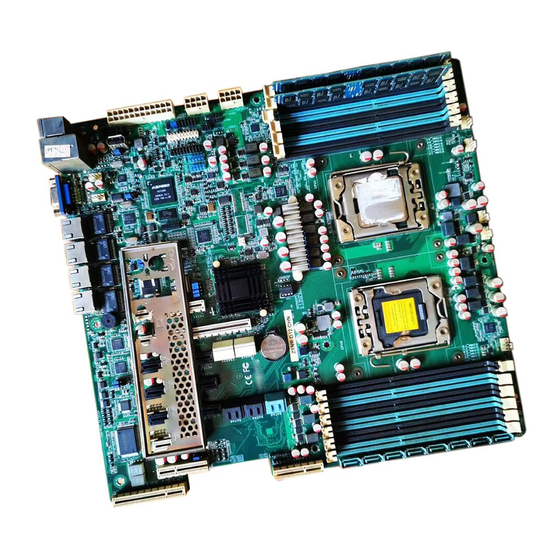
Page 25: Motherboard Layout
2.2.3 Motherboard layout Z9NR-D12 ASUS Z9NR-D12... -
Page 26: Layout Contents
2.2.4 Layout contents Slots/Socket Page CPU sockets DDR3 sockets 2-12 PCI Express x8 / PCI Express x16 slots 2-15 PIKE RAID card slot 2-18 ASMB6 header 2-19 Onboard LEDs Page DIMM Error LED (ERR_DIMM) 2-20 Baseboard Management Controller LED (BMC_LED1) 2-20 CPU Warning LED (ERR_CPU1/2) 2-21... - Page 27 Serial port connectors (10-1 pin COM1/COM2) 2-35 TPM connector (20-1-pin TPM1) 2-35 EATX power connectors (24-pin EATXPWR1, 8-pin 2-36 EATX12V1/EATX12V2) Power Supply SMBus (PSUSMB1) 2-37 System panel connector (20-1 pin PANEL1) 2-38 Auxiliary panel connector (20-2 pin AUX_PANEL1) 2-39 ASUS Z9NR-D12...
-
Page 28: Central Processing Unit (Cpu)
ASUS will shoulder the cost of repair only if the damage is shipment/transit-related. • Keep the cap after installing the motherboard. ASUS will process Return Merchandise Authorization (RMA) requests only if the motherboard comes with the cap on the LGA1356 socket. -
Page 29: Intel Lga1356 Socket
Lift the load lever in the direction of the arrow to a 135° angle (C), then lift the load plate with your thumb and forefinger to a 100° angle (D). Remove the PnP cap from the CPU socket. PnP cap ASUS Z9NR-D12... - Page 30 Position the CPU over the socket, ensuring that the gold triangle is on the bottom-left corner of the socket, and then fit the socket Gold alignment key into the CPU notch. triangle mark CPU notch Alignment key The CPU fits in only one correct orientation. DO NOT force the CPU into the socket to prevent bending the connectors on the socket and damaging the CPU! Apply some Thermal Interface Material to the exposed area of...
- Page 31 Connect the CPU fan cable to the connector on the motherboard labeled CPU_FAN1 / CPU_FAN2. DO NOT forget to connect the CPU fan connector! Hardware monitoring errors can occur if you fail to plug this connector. ASUS Z9NR-D12 2-11...
-
Page 32: System Memory
• • • • • *Refer to ASUS Server AVL for latest update. • Start installing the DIMMs from slot A1 and B1 (light blue). • Always install DIMMs with the same CAS latency. For optimum compatibility, it is recommended that you obtain memory modules from the same vendor. - Page 33 • • • • • • • • • • 11 DIMMs • • • • • • • • • • • 12 DIMMs • • • • • • • • • • • • ASUS Z9NR-D12 2-13...
-
Page 34: Installing A Dimm On A Single Clip Dimm Socket
2.4.3 Installing a DIMM on a single clip DIMM socket Unlock a DIMM socket by pressing DIMM notch the retaining clip outward. Align a DIMM on the socket such that the notch on the DIMM matches the DIMM slot key on the socket. -
Page 35: Expansion Slots
When using PCI cards on shared slots, ensure that the drivers support “Share IRQ” or that the cards do not need IRQ assignments. Otherwise, conflicts will arise between the two PCI groups, making the system unstable and the card inoperable. ASUS Z9NR-D12 2-15... -
Page 36: Interrupt Assignments
2.5.3 Interrupt assignments Standard Interrupt assignments Priority Standard function System Timer Keyboard Controller Programmable Interrupt Communications Port (COM2) Communications Port (COM1) Floppy Disk Controller System CMOS/Real Time Clock ACPI Mode when used IRQ Holder for PCI Steering IRQ Holder for PCI Steering PS/2 Compatible Mouse Port Numeric Data Processor Primary IDE Channel... -
Page 37: Pike Slots
PCIE 7 1 x PCI-E x 4 (Gen3 x1 link) 2.5.9 PIKE slots The PIKE slot allows you to choose and change your preferred SAS solution easily. Install an optional ASUS PIKE RAID card based on your needs. ASUS Z9NR-D12 2-17... -
Page 38: Installing An Asus Pike Raid Card
2.5.10 Installing an ASUS PIKE RAID card Follow the steps below to install an optional ASUS PIKE RAID card on your motherboard. Locate the PIKE RAID card slot on the motherboard. Align the golden fingers of the PIKE RAID card with the PIKE RAID card slot. -
Page 39: Installing Asmb6 Management Board
2.5.11 Installing ASMB6 management board Follow the steps below to install an optional ASMB6 management board on your motherboard. Locate the ASMB6 header on the motherboard. Orient and press the ASMB6 management card in place. ASUS Z9NR-D12 2-19... -
Page 40: Onboard Leds
Baseboard Management Controller LED (BMC_LED1) The BMC LED works with the ASUS ASMB6 management device and indicates its initiation status. When the PSU is plugged and the system is OFF, ASUS ASMB6 management device starts system initiation for about one (1) minute. - Page 41 The CPU warning LEDs light up to indicate that an impending failure of the corresponding CPU. The warning LEDs function only when you install the ASUS ASMB6. CATT Error LED (CATTERR_LED1) Indicates that the system has experienced a fatal or catastrophic error and cannot continue to operate.
- Page 42 LAN LED (LAN34_LED1) This LED indicates the connection status of LAN3 and LAN4. The LAN LEDs function only when the motherboard is installed in a server system. Q-Code LED (LED1_LED2) The Q-Code LED design provides you the 2-digit display, allowing you to know the system status.
-
Page 43: Q-Code Table
Memory Init. MRC Progress Memory Init. Done MRC Progress Other config. After RC end Progress Memory already installed. Progress CPU Init. Progress CPU Init. Progress CPU Init. Progress DXE Initial Program Load(IPL) (continued on the next page) ASUS Z9NR-D12 2-23... - Page 44 Action PHASE POST CODE TYPE DESCRIPTION Normal boot DXE(Driver Progress DXE Core Started Execution Progress DXE NVRAM Init. Environment) phase Progress SB run-time init. Progress DXE CPU Init Progress NB Init. Progress NB Init. Progress NB Init. Progress SB Init. Progress SB Init.
-
Page 45: Jumpers
Removing the cap will cause system boot failure! If the steps above do not help, remove the onboard battery and move the jumper again to clear the CMOS RTC RAM data. After the CMOS clearance, reinstall the battery. ASUS Z9NR-D12 2-25... - Page 46 VGA controller setting (3-pin VGA_EN1) This jumper allows you to enable or disable the onboard VGA controller. Set to pins 1–2 to activate the VGA feature. LAN controller setting (3-pin LAN_SW1-4) These jumpers allow you to enable or disable the onboard Intel ®...
- Page 47 Intel Rapid Storage Technology Enterprise Option ROM Utility. ® ME firmware force recovery setting (3-pin ME_RCVR1) This jumper allows you to force Intel Management Engine (ME) boot from recovery mode when ME become corrupted. ASUS Z9NR-D12 2-27...
- Page 48 DDR3 thermal event setting (3-pin DIMMTRIP1) This jumper allows you to enable/disable DDR3 DIMM thermal sensing event pin. PMBus 1.2 PSU select jumper (3-pin SMART_PSU1) This jumper allows you to select PSU PMBus version, Set to pins 1-2 for PMBus, set to pins 2-3 for Others. 2-28 Chapter 2: Hardware information...
-
Page 49: Connectors
LED indications. DM_LAN1 port LED indications ACT/LINK SPEED Activity/Link LED Speed LED Status Description Status Description No link 10 Mbps connection Orange Linked Orange 100 Mbps connection Blinking Data activity Green 1 Gbps connection DM LAN port ASUS Z9NR-D12 2-29... -
Page 50: Internal Connectors
LAN port LED indications ACT/LINK SPEED Activity/Link LED Speed LED Status Description Status Description No link 10 Mbps connection Green Linked Orange 100 Mbps connection Blinking Data activity Green 1 Gbps connection LAN port 2.8.2 Internal connectors Serial ATA 6.0/3.0 Gb/s connectors (7-pin SATA6G_1-2 [blue]; 7-pin SATA3G_3-6 [black]) These connectors connect to Serial ATA 6.0Gb/s or 3.0 Gb/s hard disk drives and optical disc drives via Serial ATA 6.0Gb/s or 3.0 Gb/s signal cables. - Page 51 The actual data transfer rate depends on the speed of SATA hard disks installed. SAS connectors— PSAS connectors (7-pin PSAS1–4 [Light Blue]; 7-pin PSAS5–8 [Black]) Supported by the ASUS PIKE Card, these connectors are for the SAS signal ® cables for SAS hard disk drives that allows up to 6Gb/s of data transfer rate.
- Page 52 Hard disk activity LED connector (4-pin HDLED1) This LED connector is for the storage add-on card cable connected to the SATA or SAS add-on card. The read or write activities of any device connected to the SATA or SAS add-on card causes the front panel LED to light up.
- Page 53 DO NOT forget to connect the fan cables to the fan connectors. Insufficient air flow inside the system may damage the motherboard components. • These are not jumpers! DO NOT place jumper caps on the fan connectors! • All fans feature the ASUS Fan Speed Control technology. ASUS Z9NR-D12 2-33...
- Page 54 Serial General Purpose Input/Output connectors (8-1 pin PSGPIO 1/2, ISGPIO1, SGPIO1) The SGPIO 1 connectors are used for the Intel Rapid Storage Technology Enterprise SGPIO interface that controls the LED pattern generation, device information and general purpose data. • The PSGPIO 1/2 connectors are used for PIKE card. •...
- Page 55 TPM connector (20-1 pin TPM1) This connector supports a Trusted Platform Module (TPM) system, which can securely store keys, digital certificates, passwords, and data. A TPM system also helps enhance network security, protects digital identities, and ensures platform integrity. ASUS Z9NR-D12 2-35...
- Page 56 10. EATX power connectors (24-pin EATXPWR1, 8-pin EATX12V1/EATX12V2) These connectors are for an EATX power supply plugs. The power supply plugs are designed to fit these connectors in only one orientation. Find the proper orientation and push down firmly until the connectors completely fit. •...
- Page 57 This connector allows you to connect SMBus (System Management Bus) to the power supply unit to read PSU information. Devices communicate with an SMBus host and/or other SMBus devices using the SMBus interface. This connector functions only when you install the ASUS ASMB6. ASUS Z9NR-D12 2-37...
-
Page 58: System Panel Connector
12. System panel connector (20-1 pin PANEL1) This connector supports several chassis-mounted functions. (1) System power LED (3-pin PLED) This 3-pin connector is for the system power LED. Connect the chassis power LED cable to this connector. The system power LED lights up when you turn on the system power, and blinks when the system is in sleep mode. - Page 59 Connect the Locator LED cables to these 2-pin connector. The LEDs will light up when the Locator button is pressed. (5) Locator Button/Swich (2-pin LOCATORBTN) These leads are for the locator button on the front panel. This button queries the state of the system locator. ASUS Z9NR-D12 2-39...
- Page 60 2-40 Chapter 2: Hardware information...
-
Page 61: Chapter 3: Powering Up
This chapter describes the power up sequence, and ways of shutting down the system. Powering up Chapter 3:... - Page 62 Chapter summary Starting up for the first time ............3-3 Powering off the computer ............3-4 ASUS Z9NR-D12...
-
Page 63: Starting Up For The First Time
Check the jumper settings and connections or call your retailer for assistance. At power on, hold down the <Del> key to enter the BIOS Setup. Follow the instructions in Chapter 4. ASUS Z9NR-D12... -
Page 64: Powering Off The Computer
Powering off the computer 3.2.1 Using the OS shut down function If you are using Windows 2008 Server: ® Click the Start button, move the cursor to the triangle on the right of Log off, and then click Shut Down. From the Shutdown Event Tracker, select the option that best describes why you want to shut down the computer. -
Page 65: Chapter 4: Bios Setup
This chapter tells how to change the system settings through the BIOS Setup menus. Detailed descriptions of the BIOS parameters are also provided. BIOS setup Chapter 4:... - Page 66 Main menu .................. 4-10 Advanced menu ................. 4-11 Server Mgmt menu ..............4-37 Event Logs menu ............... 4-40 Boot menu .................. 4-42 Monitor menu ................4-44 Security menu ................4-45 4.10 Tool menu ................... 4-46 4.11 Exit menu ..................4-47 ASUS Z9NR-D12...
-
Page 67: Managing And Updating Your Bios
4.1.1 ASUS CrashFree BIOS 3 utility The ASUS CrashFree BIOS 3 is an auto recovery tool that allows you to restore the BIOS file when it fails or gets corrupted during the updating process. You can update a corrupted BIOS file using a USB flash drive that contains the updated BIOS file. -
Page 68: Asus Ez Flash 2 Utility
4.1.2 ASUS EZ Flash 2 Utility The ASUS EZ Flash 2 Utility feature allows you to update the BIOS without having to use a DOS-based utility. Before you start using this utility, download the latest BIOS from the ASUS website at www.asus.com. -
Page 69: Bupdater Utility
Updating the BIOS file To update the BIOS file using the BUPDATER utility: Visit the ASUS website at www.asus.com and download the latest BIOS file for the motherboard. Save the BIOS file to a bootable USB flash disk drive. Copy the BUPDATER utility (BUPDATER.exe) from the ASUS support website at support.asus.com to the bootable USB flash disk drive you created... - Page 70 The utility verifies the file, then starts updating the BIOS file. ASUSTek BIOS Update for DOS V1.06 (09/08/04) FLASH TYPE: MXIC 25L1605A Update ROM Current ROM BOARD: Z9NR-D12 BOARD: Z9NR-D12 VER: 0203 VER: 0206 DATE: 08/24/2011 DATE: 09/30/2011 PATH: WARNING! Do not turn off power during flash BIOS...
-
Page 71: Bios Setup Program
The BIOS setup screens shown in this section are for reference purposes only, and may not exactly match what you see on your screen. • Visit the ASUS website (www.asus.com) to download the latest BIOS file for this motherboard. ASUS Z9NR-D12... -
Page 72: Bios Menu Screen
4.2.1 BIOS menu screen Menu items Menu bar Configuration fields General help Aptio Setup Utility - Copyright (C) 2011 American Megatrends, Inc. Main Advanced Server Mgmt Event Logs Boot Monitor Security Tool Exit Set the Date, Use Tab to BIOS Information switch between Data elements. -
Page 73: Menu Items
A scroll bar appears on the right side of a menu screen when there are items that do not fit on the screen. Press the Up/Down arrow keys or <Page Up> /<Page Down> keys to display the other items on the screen. ASUS Z9NR-D12... -
Page 74: Main Menu
Main menu When you enter the BIOS Setup program, the Main menu screen appears. The Main menu provides you an overview of the basic system information, and allows you to set the system date, time settings. Aptio Setup Utility - Copyright (C) 2011 American Megatrends, Inc. Main Advanced Server Mgmt... -
Page 75: Advanced Menu
F1: General Help DCU Streamer Prefetcher [Enabled] F2: Previous Values DCU IP Prefetcher [Enabled] F5: Optimized Defaults Intel Virtualization Technology [Enabled] F10: Save & Exit Local APIC Mode [Auto] ESC: Exit Version 2.14.1219. Copyright (C) 2011 American Megatrends, Inc. ASUS Z9NR-D12 4-11... - Page 76 Socket 1 CPU Information Enter to view socket soecific CPU Information. Aptio Setup Utility - Copyright (C) 2011 American Megatrends, Inc. Advanced Socket 1 CPU Information Enter to view socket soecific CPU Information. Intel(R) Xeon(R) CPU E5-2470 0 @ 2.30GHz CPU Signature 206d6 Microcode Patch...
-
Page 77: Cpu Power Management Configuration
Version 2.14.1219. Copyright (C) 2011 American Megatrends, Inc. Power Technology [Custom] This item allows you to enable power management features. Configuration options: [Disabled] [Energy Efficient] [Custom] EIST [Enabled] This item allows you to enable/disable Intel SpeedStep. Configuration options: [Disabled] [Enabled] ASUS Z9NR-D12 4-13... - Page 78 Turbo Mode [Enabled] Configuration options: [Disabled] [Enabled] P-STATE Coordination [HW_ALL] This item allows you to change P-STATE Coordination type. Configuration options: [HW_ALL] [SW_ALL] [SW_ANY] CPU C3 Report [Disabled] This item allows you to enabled/disabled CPU C3(ACPI C2) report. Configuration options: [Disabled] [Enabled] CPU C6 Report [Enabled] This item allows you to enabled/disabled CPU C6(ACPI C3) report.
-
Page 79: Chipset Configuration
This item allows for selecting the QPI link frequency Configuration options: [Auto] [6.4 GT/s] [7.2 GT/s (Fast Mode Only)] [8.0 GT/s (Fast Mode Only)] QPI Link0s [Disabled] Configuration options: [Disabled] [Enabled] QPI Link0p [Disabled] Configuration options: [Disabled] [Enabled] QPI Link1 [Enabled] Configuration options: [Disabled] [Enabled] ASUS Z9NR-D12 4-15... -
Page 80: Memory Configuration
Memory Configuration Aptio Setup Utility - Copyright (C) 2011 American Megatrends, Inc. Advanced Support for compatibility Compatibility RID [Enabled] Revision ID(CRID) Functionality mentioned in Memory Configuration Sandybridge bios spec. Total Memory 1024 MB (DDR3) Current Memory Mode Independent Currently Memory Speed 1333 MHz Mirroring Not Possible... - Page 81 Allow 2x Refresh [Enabled] Configuration options: [Disabled] [Enabled] Altitude [300 M] The system altitude above the sea level in meters. Configuration options: [Auto] [300 M] [900 M] [1500 M] [3000 M] Memory Hot sensor support [Enabled] Configuration options: [Disabled] [Enabled] ASUS Z9NR-D12 4-17...
-
Page 82: Dimm Information
DIMM Information Aptio Setup Utility - Copyright (C) 2011 American Megatrends, Inc. Advanced CPU1 DIMM Information Dimm_A1 Present 1024 MB Indep Dimm_A2 Not Present Dimm_B1 Not Present Dimm_B2 Not Present Dimm_C1 Not Present Dimm_C1 Not Present CPU2 DIMM Information CPU IIO Bridge Configuration Aptio Setup Utility - Copyright (C) 2011 American Megatrends, Inc. -
Page 83: Pch Configuration
Configuration options: [Disabled] [Enabled in S5] [Enabled in S4 and S5] Mobile platforms support deep S4/S5 in DC only and desktop platforms support deep S4/S5 in AC only. SCU devices [Enabled] Allows you to enable/disable Patsburg SCU devices. Configuration options: [Enabled] [Disabled] ASUS Z9NR-D12 4-19... - Page 84 Onboard SATA RAID Oprom [Enabled] Allows to enabled/disabled onboard SATA RAID option rom if Launch Storage Oprom is enabled. Configuration options: [Disabled] [Enabled] High Precision Event Timer Configuration High Precision Timer [Enabled] Allows to enabled/disabled High Precision Event Timer. Configuration options: [Disabled] [Enabled]] Intel(R) VT for Directed I/O Configuration Aptio Setup Utility - Copyright (C) 2011 American Megatrends, Inc.
-
Page 85: Pch Sata Configuration
When read/write of your hard disk errors occur, this feature allows the hard disk to report warning messages during the POST. Configuration options: [Enabled] [Disabled] Aggressive Link Power Management [Enabled] Configuration options: [Enabled] [Disabled] Port 1/2/3/4/5/6 Staggered Spin-up [Disabled] AHCI supports staggered spin-up. Configuration options: [Enabled] [Disabled] ASUS Z9NR-D12 4-21... -
Page 86: Pch Scu Configuration
4.4.5 PCH SCU Configuration This menu automatically detects and displays Device 1-4. Aptio Setup Utility - Copyright (C) 2011 American Megatrends, Inc. Advanced Device1 Not Present Device2 Not Present Device3 Not Present Device4 Not Present →←: Select Screen Select Item ↑↓: Enter: Select Item +/-: Change Opt. -
Page 87: Pci Subsystem Settings
Enables or disables PCI device to generate PERR#. Configuration options: [Disabled] [Enabled] SERR# Generation [Disabled] Enables or disables PCI device to generate SERR#. Configuration options: [Disabled] [Enabled] Load RT32 Image [Enabled] Enables or disables PCI device to load RT32 image. Configuration options: [Disabled] [Enabled] ASUS Z9NR-D12 4-23... -
Page 88: Pci Express Settings
PCI Express Settings Aptio Setup Utility - Copyright (C) 2011 American Megatrends, Inc. Advanced Enables or DisablesPCI PCI Express Link Register Settings Express Device Relaxed ASPM Support [Disabled] Ordering. WARNING: Enabling ASPM may cause some PCI-E device to fail →←: Select Screen Select Item ↑↓: Enter: Select Item... - Page 89 PCIE4 Option Rom [Enabled] Configuration options: [Disabled] [Enabled] PCIE5 Option Rom [Enabled] Configuration options: [Disabled] [Enabled] PCIE6 Option Rom [Enabled] Configuration options: [Disabled] [Enabled] PCIE7 Option Rom [Enabled] Configuration options: [Disabled] [Enabled] PIKE Option Rom [Enabled] Configuration options: [Disabled] [Enabled] ASUS Z9NR-D12 4-25...
-
Page 90: Usb Configuration
4.4.7 USB Configuration Aptio Setup Utility - Copyright (C) 2011 American Megatrends, Inc. Advanced Enabled Legacy USB support. USB Configuration AUTO option disables legacy support if no USB devices USB Devices: are connected. DISABLE 1 Keyboard, 2 Mice, 3 Hubs option will keep USB devices available only for EFI Legacy USB Support... -
Page 91: Trusted Computing
O.S. will not show Security Device. TCG EFI protocol and Current Status Information INT1A interface will not be available. Reset Required TPM SUPPORT [Enabled] Allows you to enable or disable the TPM support. Configuration options: [Disabled] [Enabled] ASUS Z9NR-D12 4-27... -
Page 92: Acpi Settings
4.4.9 ACPI Settings Aptio Setup Utility - Copyright (C) 2011 American Megatrends, Inc. Advanced Enables or Disables BIOS ACPI ACPI Settings Auto Configuration. Enable ACPI Auto Configuration [Disabled] Enabled Hibernation [Enabled] ACPI Sleep State [S1 (CPU Stop Clock)] Lock Legacy Resources [Disabled] Enable ACPI Auto Configuration [Disabled] Allows you to enable or disable BIOS ACPI Auto Configuration. -
Page 93: Apm Setting
Enables the Ring devices to generate a wake event. Power On By RTC [Disabled] [Disabled] Disables RTC from generating a wake event. When set to [Eanbled], the items RTC Alarm Date (Days) and Hour/ [Enabled] Minute/Second will become user-configurable with set values. ASUS Z9NR-D12 4-29... -
Page 94: Serial Port Console Redirection
4.4.12 Serial Port Console Redirection Aptio Setup Utility - Copyright (C) 2011 American Megatrends, Inc. Advanced Consloe Redirection Enable COM1 or Disable. Console Redirection [Disabled] Console Redirection Settings COM2 Console Redirection [Enabled] Console Redirection Settings Serial Port for Out-of-Band Management/ Windows Emergency Management Services (EMS) Console Redirection [Disabled]... -
Page 95: Console Redirection Settings
Configuration options: [80x24] [80x25] COM2 Console Redirection [Enabled] Enables or disables the console redirection feature. Configuration options: [Disabled] [Enabled] Console Redirection Settings Please refer to the description of the Console Redirection Settings item under COM1 for details. ASUS Z9NR-D12 4-31... - Page 96 Serial Port for Out-of-Band Management/ Windows Emergency Management Services (EMS) Console Redirection [Disabled] Enables or disables the console redirection feature. Configuration options: [Disabled] [Enabled] The following item appears only when you set Console Redirection to [Enabled]. Console Redirection Settings Out-of-Band Mgmt Port [COM1] Microsoft Windows Emergency Management Services (EMS) allow for remote management of a Windows Server OS through a serial port.
-
Page 97: Onboard Lan Configuration
SiEn NM →←: Select Screen Select Item ↑↓: Enter: Select Item +/-: Change Opt. F1: General Help F2: Previous Values F5: Optimized Defaults F10: Save & Exit ESC: Exit Version 2.14.1219. Copyright (C) 2011 American Megatrends, Inc. ASUS Z9NR-D12 4-33... -
Page 98: Onboard Devices Configuration
4.4.15 Onboard Devices Configuration Aptio Setup Utility - Copyright (C) 2011 American Megatrends, Inc. Advanced Set Parameters of serial Serial Port 1 Configuration Port 1(COM1). Serial Port 2 Configuration Serial Port 1/2 Configuration Aptio Setup Utility - Copyright (C) 2011 American Megatrends, Inc. Advanced Enable or Disable Serial Serial Port Configuration... -
Page 99: Server Mgmt Menu
O/S Wtd Timer Policy [Reset] Allows you to configure how the system should respond if the OS Boot Watchdog Timer expires. Not available if O/S Boot Watchdog Timer is disabled. Configuration options: [Do Nothing] [Reset] [Power Down] ASUS Z9NR-D12 4-35... -
Page 100: System Event Log
4.5.1 System Event Log Aptio Setup Utility - Copyright (C) 2011 American Megatrends, Inc. Server Mgmt Change this to enable or Enabling/Disabling Options disable all features of SEL Components [Disabled] system Event Logging during boot. Erasing Settings Erase SEL [No] When SEL is Full [Do Nothing] Note: All values changed here do not take effect... -
Page 101: Bmc Network Configuration
The following items appears only when you set Configuration Address source to [Static Mode]. Station IP address [0.0.0.0] Allows you to input Station IP address. Subnet mask [0.0.0.0] Allows you to input Subnet mask. Gateway IP address [0.0.0.0] Allows you to input Gateway IP address. ASUS Z9NR-D12 4-37... -
Page 102: Event Logs Menu
Event Logs menu The Event Logs allows you to change or view the event log settings. Aptio Setup Utility - Copyright (C) 2011 American Megatrends, Inc. Main Advanced Server Mgmt Event Logs Boot Monitor Security Tool Exit Press <Enter> to change Change Smbios Event Log Settings the Smbios Event Log configuration. -
Page 103: View Smbios Event Log
Enable or disable the converting of EFI Status Codes to Standard Smbios Types (Not all may be translated). Configuration options: [Disabled] [Enabled] View Smbios Event Log Press <Enter> to view all smbios event logs. View System Event Log Press <Enter> to view all system event logs. ASUS Z9NR-D12 4-39... -
Page 104: Boot Menu
Full Screen Logo [Enabled] Allows you to enable or disable the full screen logo display feature. Configuration options: [Disabled] [Enabled] Set this item to [Enabled] to use the ASUS MyLogo2™ feature. CSM16 Module Version GateA20 Active [Upon Request] [Upon Request] GA20 can be disabled using BIOS services. - Page 105 The number of device items that appears on the screen depends on the number of devices installed in the system. • To select the boot device during system startup, press <F8> when ASUS Logo appears. • To access Windows OS in Safe Mode, please press <F8> after POST.
-
Page 106: Monitor Menu
Monitor menu The Monitor menu displays the system temperature/power status, and allows you to change the fan settings. Aptio Setup Utility - Copyright (C) 2011 American Megatrends, Inc. Main Advanced Server Mgmt Event Logs Boot Monitor Security Tool Exit CPU1 Temperature CPU2 Temperature TR1 Temperature TR2 Temperature... -
Page 107: Security Menu
FAN Speed Control [Generic Mode] Allows you to configure the ASUS Smart Fan feature that smartly adjusts the fan speeds for more efficient system operation. Configuration options: [Generic Mode] [High Speed Mode] [Full Speed Mode] Security menu The Security menu items allow you to change the system security settings. -
Page 108: 4.10 Tool Menu
Be used to update BIOS ASUS EZ Flash 2 Utility ASUS EZ Flash 2 Utility Allows you to run ASUS EZ Flash BIOS ROM Utility when you press <Enter>. Check section 4.1.2 ASUS EZ Flash 2 Utility for details. 4-44... -
Page 109: 4.11 Exit Menu
Restore Defaults This option allows you to restore/load defaults values for all the setup options. When you select this option or if you press <F5>, a confirmation window appears. Select Yes to load optimized defaults. ASUS Z9NR-D12 4-45... - Page 110 Boot Override These items displays the available devices. The device items that appears on the screen depends on the number of devices installed in the system. Click an item to start booting from the selected device. Launch EFI Shell from filesystem device This item is for launching the EFI Shell application from one of the available filesystem devices.
- Page 111 This chapter provides instructions for setting up, creating, and configuring RAID sets using the available utilities. RAID configuration...
- Page 112 Chapter summary Setting up RAID ................5-3 LSI Software RAID Configuration Utility ........5-5 Intel Rapid Storage Technology enterprise SCU / SATA ® Option ROM Utility ..............5-25 Intel Rapid Storage Technology enterprise Utility(Windows) ... 5-35 ® ASUS Z9NR-D12...
-
Page 113: Setting Up Raid
• Please refer to chapter 2 for how to select the RAID configuration utility. Move the jumper to choose between LSI MegaRAID and Intel ® Rapid RAID. ASUS Z9NR-D12... -
Page 114: Installing Hard Disk Drives
5.1.2 Installing hard disk drives The motherboard supports Serial ATA for RAID set configuration. For optimal performance, install identical drives of the same model and capacity when creating a disk array. To install the SATA hard disks for RAID configuration: Install the SATA hard disks into the drive bays following the instructions in the system user guide. -
Page 115: Lsi Software Raid Configuration Utility
The keys on the legend box vary according to the menu level. LSI Software RAID Configuration Utility Ver C.05 Sep 17, 2010 BIOS Version A.10.09231523R Management Menu Configure Initialize Objects Rebuild Check Consistency Configure VD(s) Use Cursor Keys to Navigate Between Items And Press Enter To Select An Option ASUS Z9NR-D12... -
Page 116: Creating A Raid Set
Menu Description Configure Allows you to create RAID 0, RAID 1 or RAID 10 set using the Easy Configuration or the New Configuration command. This menu also allows you to view, add, or clear RAID configurations or select the boot drive Initialize Allows you to initialize the virtual drives of a created RAID set Objects... - Page 117 LSI Software RAID Configuration Utility Ver C.05 Sep 17, 2010 BIOS Version A.10.09231523R Easy Configuration - ARRAY SELECTION MENU Select Configurable Array(s) Management Menu PORT # Configure DNLIN A00-00 SPAN-1 Initialize Objects DNLIN A00-01 Rebuild Check Consistency Cursor Keys, SPACE-(De)Select F2-ChIdInfo F3-SlotInfo F10-Configure Esc-Quit ASUS Z9NR-D12...
- Page 118 Press <F10> again, the virtual drive information appears including a Virtual Drive menu that allows you to change the virtual drive parameters. LSI Software RAID Configuration Utility Ver C.05 Sep 17, 2010 BIOS Version A.10.09231523R Virtual Drive(s) Configured RAID Size #Stripes StripSz Status...
- Page 119 = On Accept SPAN = NO Disk Write Cache Setting Of VD Use Cursor Keys To Navigate Between Items And Press Enter To Select An Option Enabling DWC can improve the performance, but with the risk of data loss. ASUS Z9NR-D12...
- Page 120 12. When finished setting the selected virtual drive configuration, select Accept from the menu, and then press <Enter>. LSI Software RAID Configuration Utility Ver C.05 Sep 17, 2010 BIOS Version A.10.09231523R Virtual Drive(s) Configured RAID Size #Stripes StripSz Status Easy Configuration - ARRAY SELECTION MENU Management Menu 148.580GB 64 KB...
-
Page 121: Using New Configuration
SPAN = NO Enter VD Size: Use Cursor Keys to Navigate Between Items And Press Enter To Select An Option Follow step 10 to 14 of the previous section: Using Easy Configuration to create the RAID set. ASUS Z9NR-D12 5-11... -
Page 122: Adding Or Viewing A Raid Configuration
5.2.2 Adding or viewing a RAID configuration You can add a new RAID configuration or view an existing configuration using the View/Add Configuration command. Adding a new RAID configuration To add a new RAID configuration: From the Management Menu, select Configure > View/Add Configuration, and then press <Enter>. -
Page 123: Initializing The Virtual Drives
LSI Software RAID Configuration Utility Ver C.05 Sep 17, 2010 BIOS Version A.10.09231523R Virtual Drive(s) Configured Management Menu RAID Size #Stripes StripSz Status Configure Initialize 148.580GB 64 KB ONLINE Objects Rebuild Check Consistency Virtual Drives Virtual Drive 0 Select VD SPACE-(De)Select, F10-Initialize ASUS Z9NR-D12 5-13... - Page 124 Press <F10> to start initialization. When prompted, select Yes from the Initialize? dialog box, and then press <Enter>. LSI Software RAID Configuration Utility Ver C.05 Sep 17, 2010 BIOS Version A.10.09231523R Virtual Drive(s) Configured Management Menu RAID Size #Stripes StripSz Status Configure Initialize...
- Page 125 LSI Software RAID Configuration Utility Ver C.05 Sep 17, 2010 BIOS Version A.10.09231523R Vitual Drive(1) Virtual Drive 0 Objects Management Menu Adapter Configure Virtual Drive Initialize Physical Drive Objects Rebuild Check Consistency Select VD Press ENTER To Select A VD, <Del> To Delete A VD ASUS Z9NR-D12 5-15...
- Page 126 Select Initialize from the pop-up menu, and then press <Enter> to start initialization. LSI Software RAID Configuration Utility Ver C.05 Sep 17, 2010 BIOS Version A.10.09231523R Vitual Drive(1) Virtual Drive 0 Objects Management Menu Adapter Configure Virtual Drive Initialize Physical Drive Objects Vitual Drive(0) Rebuild...
-
Page 127: Rebuilding Failed Drives
LSI Software RAID Configuration Utility Ver C.05 Sep 17, 2010 BIOS Version A.10.09231523R REBUILD - PHYSICAL DRIVES SELECTION MENU Management Menu PORT # Configure ONLIN A00-00 Initialize Objects FAIL A00-01 Rebuild Check Consistency Port # 1 DISK 77247MB HDS728080PLA380 PF20A60A SPACE-(De)Select,F10-Start Rebuild,F2-Drive Information,F3-View Virtual Drives ASUS Z9NR-D12 5-17... - Page 128 After selecting the drive to rebuild, press <F10>. When prompted, press <Y> to rebuild the drive. LSI Software RAID Configuration Utility Ver C.05 Sep 17, 2010 BIOS Version A.10.09231523R REBUILD - PHYSICAL DRIVES SELECTION MENU Management Menu PORT # Configure ONLIN A00-00 Initialize Objects...
-
Page 129: Checking The Drives For Data Consistency
LSI Software RAID Configuration Utility Ver C.05 Sep 17, 2010 BIOS Version A.10.09231523R Virtual Drive(s) Configured Management Menu RAID Size #Stripes StripSz Status Configure Initialize 148.580GB 64 KB ONLINE Objects Rebuild Check Consistency Virtual Drives Virtual Drive 0 Select VD SPACE-(De)Select, F10-Check Consistency ASUS Z9NR-D12 5-19... - Page 130 When prompted, use the arrow keys to select Yes from the Consistency Check? dialog box, and then press <Enter>. LSI Software RAID Configuration Utility Ver C.05 Sep 17, 2010 BIOS Version A.10.09231523R Virtual Drive(s) Configured Management Menu RAID Size #Stripes StripSz Status Configure...
- Page 131 Select Check Consistency from the pop-up menu, and then press <Enter>. When prompted, use the arrow keys to select Yes from the dialog box to check the drive. When checking is complete, press any key to continue. ASUS Z9NR-D12 5-21...
-
Page 132: Deleting A Raid Configuration
5.2.6 Deleting a RAID configuration To delete a RAID configuration From the Management Menu, select Configure > Clear Configuration, and then press <Enter>. LSI Software RAID Configuration Utility Ver C.05 Sep 17, 2010 BIOS Version A.10.09231523R Configuration Menu Easy Configuration New Configuration Management Menu Configure... -
Page 133: Selecting The Boot Drive From A Raid Set
Select Boot Drive Objects Rebuild Check Consistency Select A Boot VD Use Cursor Keys To Navigate Between Items And Press Enter To Select An Option The virtual drive is selected as boot drive. Press any key to continue. ASUS Z9NR-D12 5-23... -
Page 134: Enabling Writecache
5.2.8 Enabling WriteCache You may manually enable the RAID controller’s WriteCache option after creating a RAID set to improve the data transmission performance. When you enable WriteCache, you may lose data when a power interruption occurs while transmitting or exchanging data among the drives. The WriteCache function is recommended for RAID 1 and RAID 10 sets. -
Page 135: Intel ® Rapid Storage Technology Enterprise Scu/Sata Option Rom Utility
To use SCU SATA ports: Install all the SATA hard disk drives. Confirm all the SATA hard disk drives you installed are correctly displayed, then reboot system. During POST, press <Ctrl+I> to display the utility main menu. ASUS Z9NR-D12 5-25... - Page 136 To enter the Intel Rapid Storage Technology enterprise SCU Option ROM utility: ® Install all the Serial ATA hard disk drives. Turn on the system. During POST, press <Ctrl+I> to display the utility main menu. Intel(R) Rapid Storage Technology enterprise - SATA Option ROM - 3.0.0.1104 Copyright(C) 2003-11 Intel Corporation.
-
Page 137: Creating A Raid Set
Select 2 to 6 disks to use in creating the volume. [ ↑↓ ]-Prev/Next [SPACE]-SelectDisk [ENTER]-Done Use the up/down arrow key to select a drive, and then press <Space> to select. A small triangle marks the selected drive. Press <Enter> after completing your selection. ASUS Z9NR-D12 5-27... - Page 138 Use the up/down arrow keys to select the stripe size for the RAID array (for RAID 0, 10 and 5 only), and then press <Enter>. The available stripe size values range from 4 KB to 128 KB. The following are typical values: RAID 0: 128KB RAID 10: 64KB RAID 5: 64KB...
-
Page 139: Deleting A Raid Set
(This does not apply to Recovery volumes) Are you sure you want to delete volume “Volume0”? (Y/N): Press <Y> to delete the RAID set and return to the utility main menu, or press <N> to return to the DELETE VOLUME menu. ASUS Z9NR-D12 5-29... -
Page 140: Resetting Disks To Non-Raid
5.3.4 Resetting disks to Non-RAID Take caution before you reset a RAID volume hard disk drive to non-RAID. Resetting a RAID volume hard disk drive deletes all internal RAID structure on the drive. To reset a RAID set hard disk drive: From the utility main menu, select 3. -
Page 141: Exiting The Intel ® Rapid Storage Technology Utility
Select the port of destination disk for rebuilding (ESC to exit): Port Drive Model Serial # Size XXXXXXXXXXX XXXXXXXX XX.XGB [ ↑↓ ]-Previous/Next [ENTER]-Select [ESC]-Exit Select a destination disk with the same size as the original hard disk. ASUS Z9NR-D12 5-31... -
Page 142: Rebuilding The Raid With A New Hard Disk
The utility immediately starts rebuilding after the disk is selected. The status of the degraded RAID volume is changed to “Rebuild”. Intel(R) Rapid Storage Technology enterprise - SATA Option ROM - 3.0.0.1104 Copyright(C) 2003-11 Intel Corporation. All Rights Reserved. MAIN MENU 1. -
Page 143: Setting The Boot Array In The Bios Setup Utility
Use up/down arrow keys to select the boot priority and press <Enter>. See section 4.7 Boot menu for details. From the Exit menu, select Save Changes & Exit, then press <Enter>. When the confirmation window appears, select Yes, then press <Enter>. ASUS Z9NR-D12 5-33... -
Page 144: Intel ® Rapid Storage Technology Enterprise Utility (Windows)
® Intel Rapid Storage Technology enterprise Utility (Windows) The Intel ® Rapid Storage Technology enterprise utility allows you to create RAID 0, RAID 1, RAID 10 (RAID 1+0), and RAID 5 set(s) from Serial ATA hard disk drives that are connected to the Serial ATA connectors supported by the Southbridge. You need to manually install the Intel ®... -
Page 145: Creating A Raid Set
If you hard disk with existing data and you don’t want to keep data from one of the selected disks, choose NO in next column (If displayed). If you want to Enable volume write-back cache or Initialize volume, you • can click Advanced tab to slelect. ASUS Z9NR-D12 5-35... - Page 146 Confirm volume creation, than click Create Volume to continue. This process could take a while depending on the number and size of the disks. You can continue using other applications during this time. When display Volume Ceation Complete message, you can click OK to finish. You still need to partition your new volume using Windows Disk Management before adding any data.
-
Page 147: Change Volume Type
128 KB. The following are typical values: RAID 0: 128KB RAID 10: 64KB RAID 5: 64KB We recommend a lower stripe size for server systems, and a higher stripe size for multimedia computer systems used mainly for audio and video editing. ASUS Z9NR-D12 5-37... -
Page 148: Delete Volume
5.4.3 Delete volume Take caution when deleting a volume. You will lose all data on the hard disk drives.Back up data before continuing. To delete a volume: From the utility main menu, select the volume (exp. Volume_0000) in Volumes field you want to delete. Then select Delete volume in Volume Properties field. -
Page 149: Preferences
Allow you set to show the notification area icon and show system information, warning, or errors here. E-Mail Preferences Allow you set to sent e-mail of the following events: Storage system information Storage system warnings Storage system errors ASUS Z9NR-D12 5-39... - Page 150 5-40 Chapter 5: RAID configuration...
-
Page 151: Chapter 6: Driver Installation
This chapter provides the instructions for installing the necessary drivers for different system components. Driver Chapter 6: installation... - Page 152 VGA driver installation............... 6-22 Intel C600 Series Chipset SCU SATA RAID Drivers ....6-25 ® Intel Rapid Storage Technology enterprise 3.0 installation . 6-26 ® Intel WG82574L Gigabit Adapters Driver installation .... 6-29 ® Management applications and utilities installation ....6-33 ASUS Z9NR-D12...
-
Page 153: Raid Driver Installation
<Enter> to enter the sub-menu. C600 INTEL RAID Driver C600 INTEL RAID Driver Windows 32 bit (AHCI / AHCI RAID) Windows 64 bit (AHCI / AHCI RAID) Windows 32 bit (SCU RAID) Windows 64 bit (SCU RAID) Back Exit ASUS Z9NR-D12... - Page 154 LSI 2008 SAS2 Driver LSI 2008 SAS2 Driver Windows XP 32 bit Windows XP 64 bit Windows Server 2003 32 bit Windows Server 2003 64 bit Windows Vista 32 bit Windows Vista 64 bit Windows Server 2008 32 bit Windows Server 2008 64 bit Windows 7 32 bit Windows 7 64 bit Windows Server 2008 R2 64 bit...
- Page 155 Insert a blank formatted high-density floppy disk to the USB floppy disk drive. Type dd if=XXX.img of=/dev/fd0 to decompress the file into the floppy disk from the following path in the support DVD: For LSI MegaRAID Driver \Drivers\C600 LSI RAID\Driver\makedisk\Linux Eject the floppy disk. ASUS Z9NR-D12...
-
Page 156: Installing The Raid Controller Driver
6.1.2 Installing the RAID controller driver During Windows Server 2008 OS installation ® To install the RAID controller driver when installing Windows Server 2008 OS ® Boot the computer using the Windows Server 2008 OS installation disc. ® Follow the screen instructions to start installing Windows Server 2008. When prompted to choose a type of installation, click Custom (advanced). - Page 157 When the system finishes loading the RAID driver, replace the motherboard Support DVD with the Windows Server installation disc. Select the drive to install Windows and click Next. Setup then proceeds with the OS installation. Follow screen instructions to continue. ASUS Z9NR-D12...
- Page 158 Red Hat Enterprise Linux OS 5.6 ® To install the LSI MegaRAID controller driver when installing Red Hat Enterprise ® Boot the system from the Red Hat OS installation CD. ® At the boot:, type linux dd noprobe=ata1 noprobe=ata2..., then press <Enter>.
- Page 159 When the installation is completed, DO NOT click Reboot. Press <Ctrl> + <Alt> + <F2> to switch to the command-line interface from graphic user interface. Type the following commands when using a Legacy floppy. mkdir /mnt/driver mount /dev/fd0 /mnt/driver cd /mnt/driver sh replace_ahci.sh reboot ASUS Z9NR-D12...
- Page 160 Red Hat Enterprise Linux OS 6.1 ® To install the LSI MegaRAID controller driver when installing Red Hat Enterprise ® Boot the system from the Red Hat OS installation CD. ® Press <Tab> to edit options. Entering the following command at the boot: linux dd blacklist=isci blacklist=ahci nodmraid , then press <Enter>.
- Page 161 You have multiple devices which could serve as source for a driver disk. Choose one you like to use and select OK, then press <Enter>. Driver Disk Sou8rce You have multiple devices which could serve as source for a driver disk. Which would you like to use? Cancel ASUS Z9NR-D12 6-11...
- Page 162 Insert the Red Hat Enterprise RAID driver disk to the USB floppy disk drive, ® select OK, then press <Enter>. Insert Driver Disk Insert your driver disk into /dev/sdb and press “OK” to continue. Back The drivers for the RAID card are installed to the system. When asked if you will load additional RAID controller drivers, select No, then press <Enter>.
- Page 163 Mount the image file into the image folder using this command format: mount -o loop [image file name] image Example: mount -o loop megasr-15-15.00.0120.2012-1-sles11- ga-x86__64.img image Copy the contents of the image directory, labeled as 01, into a FAT32 USB drive. Rename the 01 folder to CD Image. ASUS Z9NR-D12 6-13...
- Page 164 Installing SUSE Linux 11 OS To install the LSI MegaRAID controller driver when installing SUSE Linux Enterprise Server OS: Boot the system from the SUSE OS installation CD. Use the arrow keys to select Installation from the Boot Options menu. Press <F6>, then select Yes from the menu.
- Page 165 When below screen appears, select the USB floppy disk drive (sda) as the driver update medium. Select OK, then press <Enter>. Please choose the Driver Update medium. sda: USB Floppy Other device Back Select Back and follow the onscreen instructions to finish the installation. ASUS Z9NR-D12 6-15...
-
Page 166: Intel ® Chipset Device Software Installation
® Intel chipset device software installation This section provides the instructions on how to install the Intel ® chipset device software on the system. You need to manually install the Intel chipset device software on a Windows ® operating system. To install the Intel ®... - Page 167 Select Yes to accept the terms of the License Agreement and continue the process. Read the Readme File Information and press Next to continue the installation. After completing the installation, click Next to complete the setup process. ASUS Z9NR-D12 6-17...
- Page 168 Select Yes, I want to restart my computer now and click Finish to restart your computer before using the program. 6-18 Chapter 6: Driver installation...
-
Page 169: Intel Network Connections Software Installation
DVD to locate the file ASSETUP.EXE from the BIN folder. Double- click the ASSETUP.EXE to run the DVD. Click the Intel Network Connections Software to begin installation. ® Click Install Drivers and Software option to begin installation. ASUS Z9NR-D12 6-19... - Page 170 Click Next when the Intel(R) Network Connections–InstallShield Wizard window appears. Select Modify and then click Next to continue. Click the Intel(R) PROSet for Windows Device Manager box, and then click Next to start the installation. 6-20 Chapter 6: Driver installation...
- Page 171 Follow the screen instructions to complete installation. When finished, press Finish to continue. ASUS Z9NR-D12 6-21...
-
Page 172: Vga Driver Installation
VGA driver installation This section provides the instructions on how to install the ASPEED Video Graphics Adapter (VGA) driver. You need to manually install the ASPEED VGA driver on a Windows operating ® system. To install the ASPEED VGA driver: Restart the computer, and then log on with Administrator privileges. - Page 173 Toggle I accept the terms in the license agreement and click Next to continue. Enter the user information and click Next to continue. Select a setup type and click Next to continue. ASUS Z9NR-D12 6-23...
- Page 174 Click Install to start driver installation. When the installation completes, click Finish to restart your computer before using the program. 6-24 Chapter 6: Driver installation...
-
Page 175: Intel ® C600 Series Chipset Scu Sata Raid Drivers
DVD to locate the file ASSETUP.EXE from the BIN folder. Double-click the ASSETUP.EXE to run the support DVD. Click the item Intel C600 Series Chipset SCU SATA RAID Drivers from the ® menu, and then follow the onscreen instructions to complete the installation. ASUS Z9NR-D12 6-25... -
Page 176: Intel ® Rapid Storage Technology Enterprise 3.0 Installation
® Intel Rapid Storage Technology enterprise 3.0 installation This section provides the instructions on how to install the Intel ® Rapid Storage Technology enterprise 3.0 on the system. You need to manually install the Intel Rapid Storage Technology enterprise 3.0 ®... - Page 177 Read the Warning message and click Next to continue. Read the License Agreement and click Yes to continue. Read the Readme File Information and click Next to continue. ASUS Z9NR-D12 6-27...
- Page 178 After completing the installation, click Next to complete the setup process. Select Yes, I want to restart my computer now and click Finish to restart your computer before using the program. 6-28 Chapter 6: Driver installation...
-
Page 179: Intel ® Wg82574L Gigabit Adapters Driver Installation
If Autorun is NOT enabled in your computer, browse the contents of the support DVD to locate the file AUTORUN.EXE and double-click the AUTORUN.EXE and follow step 4 to run the installation. Click Intel WG82574L Gigabit Adapters Driver. ® ASUS Z9NR-D12 6-29... - Page 180 When the Intel Network Connections – InstallShield Wizard window ® appears, click Next to start the installation. Select Modify and then click Next to continue. 6-30 Chapter 6: Driver installation...
- Page 181 Select the programs you want to install and click Next to continue. Click Install to start the installation. ASUS Z9NR-D12 6-31...
- Page 182 The programs you select are being installed. Click Finish to finish the installation. 10. Restart your computer before using the program. 6-32 Chapter 6: Driver installation...
-
Page 183: Management Applications And Utilities Installation
The contents of the support DVD are subject to change at any time without notice. Visit the ASUS website (www.asus.com) for updates. 6.8.1 Running the support DVD Place the support DVD to the optical drive. -
Page 184: Utilities Menu
Intel RAID driver disks. 6.8.5 Contact information Click the Contact tab to display the ASUS contact information. You can also find this information on the inside front cover of this user guide. 6-34 Chapter 6: Driver installation... -
Page 185: Appendix: Reference Information
This appendix includes additional information that you may refer to when configuring the motherboard. Reference information Appendix:... -
Page 186: A.1 Z9Nr-D12 Block Diagram
Appendix summary Z9NR-D12 block diagram .............A-3 ASUS Z9NR-D12... -
Page 187: Z9Nr-D12 Block Diagram
Z9NR-D12 block diagram ASUS Z9NR-D12... - Page 188 Appendix A: Reference information...
-
Page 189: Asus Contact Information
800 Corporate Way, Fremont, CA 94539, USA +1-510-608-4555 Web site http://usa.asus.com Technical Support Support fax +1-812-284-0883 General support +1-812-282-2787 Online support http://support.asus.com/techserv/techserv.aspx ASUS COMPUTER GmbH (Germany and Austria) Address Harkort Str. 21-23, D-40880 Ratingen, Germany +49-2102-959911 Web site http://www.asus.de Online contact http://www.asus.de/sales Technical Support Telephone +49-1805-010923*...
Need help?
Do you have a question about the Z9NR-D12 and is the answer not in the manual?
Questions and answers