Cub Cadet GTX1054 Operator's Manual
Hydrostatic garden tractor
Hide thumbs
Also See for GTX1054:
- Operator's manual (36 pages) ,
- Compatibility manual (3 pages) ,
- Brochure (2 pages)
Table of Contents

Related Manuals for Cub Cadet GTX1054


Summary of Contents for Cub Cadet GTX1054
- Page 1 Safe Operation Practices • Set-Up • Operation • Maintenance • Service • Troubleshooting • Warranty ATOR S ANUAL Hydrostatic Garden Tractor m GTX1054 CUB CADET LLC, P.O. BOX 361131 CLEVELAND, OHiO 44136-0019 PrintedIn USA FormNo.769-05510 (January 4, 2010)
-
Page 2: Customer Support
Visit us on the web at www.cubcadetcom Call a Customer Support Representative at (800) 965-4CUB Locate your nearest Cub Cadet Dealer at (877) 282-8684 Write us at Cub Cadet LLC • RO. Box 361131 • Cleveland, OH • 44136-0019... -
Page 3: Important Safe Operation Practices
ImportantSafeOperation Practices WARNING! This symbol points out important safety instructions which, if not followed, could endanger the personal safety and/or property of yourself and others. Read and follow all instructions in this manual before attempting to operate this machine. Failure to comply with these instructions may result in personal injury. - Page 4 12. Amissing ordamaged discharge cover can cause blade Slope Operation contact orthrown o bject injuries. Slopes are a major factor related to loss of control and tip-over 13. Stop t heblade(s) when crossing gravel drives, walks, or accidents which can result in severe injury or death. All slopes roads a nd while notcutting g rass.
-
Page 5: Safe Handling Of Gasoline
Children Service Tragic accidents ca n occur if the operator is not alert to the SafeHandling of Gasoline: presence of children. Children are often attracted to the machine and the mowing activity. They do not understand To avoid personal injury or property damage use extreme the dangers. -
Page 6: Spark Arrestor
Periodically check to make sure the blades come to Donot modify engine complete stop within approximately (5) five seconds after To avoid serious injury or death, do not modify engine in any operating the blade disengagement control. If the blades way. -
Page 7: Safety Symbols
SafetySymbols This page depicts and describes safety symbols that may appear on this product. Read, understand, and follow all instructions on the machine before attempting to assemble and operate. READ THE OPERATOR'S MANUAL(S) Read, understand, and follow all instructions in the manual(s) before attempting assemble and operate DANGER--... - Page 8 or a corner of a building... or a fence post ' FOldo,_ " .- 22 diine a 15Oslope "o 15 ° Usethis page as a guide to determine slopeswhere you may not operate safely. WARNING! Do not operate your lawn mower on such slopes. Do not mow on inclines with a slope in excess of 15 degrees (a rise of approximately 2-1/2 feet every 10 feet).
-
Page 9: Assembly And Setup
Assembly & Set-Up Contents of Crate One Garden Tractor One Oil Drain Tube One DeckWash Hose Coupler One Garden Tractor Operator's One Kohler Engine Operator's One Product Registration Card Manual Manual Shipping BraceRemoval TractorSet-Up Moving TheTractorManually is off, set the parking brake and remove the ignition Your tractor's transmission... -
Page 10: Connecting The Battery Cables
Checking Tire Pressure Connecting the Battery Cables WARNING! Never exceed the maximum inflation CALiFORNiA PROPOSiTiON 65 WARNING! pressure shown on the sidewall of the tire. Do not Battery posts, terminals, and related accessories overinflate tires. Check sidewall of tires for maximum contain lead and lead compounds, chemicals... -
Page 11: Adjusting The Seat
Gasand 0il Position the deck roller brackets up or down through the slots on the rear of the deck until desired The fuel tank is located under the hood and has a capacity position is reached, then reattach with the clevis three and-a-half gallons. -
Page 12: Controls And Features
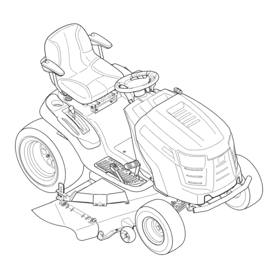
Controls a nd Features Systems indicator Monitor Fuel Tank Ca ignition Switch Module Throttle/Choke Control PTO Knob Drive Pedal Brake Pedal Pedal Parking Brake/ Cruise Control Lever Deck Lift Lever Seat Adjustment Lever Cup Holder Stora_ Figure 4-1 Throttle/Choke Control Lever Garden Tractor controls and features are illustrated in Fig. -
Page 13: Decklift Lever
Charge the battery as instructed in the Service section of this manual or have the charging system checked your Cub Cadet dealer. SECTION 4 CONTROLS AND FEATURES... - Page 14 PTO / BladeEngageKnob Activating the PTO engages power to the cutting deck or other (separately available) attachments. Pull outward on the PTO/Blade Engage knob to activate it. Push the PTO/ Blade Engage knob inward to disengage the power to the cutting deck or other (separately available)
-
Page 15: Operation
If the interlock system should ever malfunction, do not operate the tractor. Contact your Cub Cadet NOTE: Do NOT leave the choke on while operating the tractor. dealer. Doing so will result in a "rich" fuel mixture and cause the engine to run poorly. -
Page 16: Driving The Tractor
Reverse Caution Mode DrivingTheTractor The REVERSE CAUTION MODE position of the key switch module allows the tractor to be operated in reverse with the blades (PTO) and sudden stops. i_lk WARNING! Avoid sudden starts, excessive speed engaged. NOTE: Mowing in reverse is not recommended. Lightly press the brake pedal to release the parking brake. -
Page 17: Driving On Slopes
Cruise Control Driving OnSlopes Refer to the SLOPE GAUGE on page 8 to help determine slopes while traveling in reverse. where you may operate the tractor safely. ARNING! Never engage the cruise control lever excess of 15 degrees (a rise of approximately 2-1/2 To set the cruise control:... -
Page 18: Engagingthe Pto
Engagingthe PTO Mowing Engaging the PTO transfers power to the cutting deck or other WARNING! To help avoid blade contact or a (separately available) attachments. To engage the PTO: thrown object injury, keep bystanders, helpers, children and pets at least 75 feet from the machine Move the throttle control lever to the FAST (rabbit) -
Page 19: Maintenance And Adjustments
Maintenance & Adjustments MaintenanceSchedule Before Every Every Every Every Prior Eachuse 10 Hours 25 Hours 50 Hours 100 Hours to Storing CleanHood/Dash Louvers Check Engine Oil Level Check Air Filterfor Dirty,Looseor Damaged Parts _" CleanandRe-oilAir Filter'sFoamPre-Cleaner Replace Air Filter Element ChangeEngineOiland Replace Oil Filter CleanBattery Terminals LubeFrontAxlesand Rims... -
Page 20: Cleaningthe Tractor
Pop open the protective cap on the end of the oil drain SparkPlug valve to expose the drain port. See Fig 6-1. The spark plug should be cleaned and the gap reset once a season. Refer to the Kohler Owner's Manual for correct plug type and gap specifications. -
Page 21: Front Wheels
FrontWheels Attach the hose coupler to the water port on your deck's surface. See Fig. 6-2. Each of the front wheel axles and rims is equipped with a grease fitting. See Fig. 6-3. Lubricate with a No. 2 multi-purpose grease applied with a grease gun after every 25 hours of tractor operation. - Page 22 Determine the approximate distance necessary for proper DeckSpindle adjustment and )roceed, if necessary. Grease fittings can be found on each deck spindle. See Fig. 6-4. Loosen (thread outward) the hex lock nut on the end of the Lubricate with 251H EP grease or an equivalent No.
- Page 23 Leveling the Deck(Sideto Side) Steering Adjustment If the cutting deck appears to be mowing unevenly, a side to side If the tractor turns tighter in one direction than the other, or if adjustment can be performed. Adjust if necessary as follows: the ball joints are being replaced due to damage...
- Page 24 DeckRear Roller Adjustment The rear rollers on the mower deck are not designed to carry the weight of the deck. The rear rollers should be adjusted approximately 1/4"to 1/2"above the ground when the deck is moved to the desired cutting height.
-
Page 25: Cutting Deckremoval
Service NOTE: If there is too much tension on the belt for it to be Cutting DeckRemoval easily removed from the electric PTO clutch, carefully insert To remove the cutting deck, proceed as follows: a %" drive ratchet wrench (set to tighten) into the square hole found in the left-hand deck idler bracket and pivot it... - Page 26 Cutting fllates Pull the deck support pin outward to release the deck from the deck lift arm. See Fig. 7-3. ignition key before removing the cutting blade(s) for _ ..........ARNING! Shut the engine offand remove sharpening or replacement. Protect your hands by using heavy gloves when grasping the blade spindle for cracks or damage,...
- Page 27 To properly sharpen the cutting blades, remove equal Battery amounts of metal from both ends of the blades along the CALIFORNIA PROPOSiTiON 65 WARNING! cutting edges, parallel to the trailing edge, at a 25 °- to 30 ° angle. Always grind each cutting blade edge equally Battery posts, terminals, and related accessories...
-
Page 28: Changingthe Deckbelt
Remove the deck belt from around the three spindle Fuse pulleys and the two deck idler pulleys. NOTE:The idler pulleys may have to be loosened, but not inspecting, always disengage PTO, set parking removed, in order to remove the belt from around them. i _lll_llilk WARNING! Before servicing,... - Page 29 PTO pulley. Changingthe TransmissionDriveBelt Several components must be removed and special tools used in order to change the tractor's transmission drive belt. See your Cub Cadet dealer to have the transmission drive belt replaced. SECTION 7 -- SERVICE...
-
Page 30: Troubleshooting
Troubleshooting Problem Cause Remedy Engine runs erratic 1. Tractor running with CHOKE activated. 1. Move Choke control out of CHOKE position. 2. Spark plug wire(s) loose. 2. Connect spark plug wire(s). 3. Blocked fuel line or stale fuel. 3. Clean fuel line; fill tank with clean, fresh gasoline and replace fuel filter. -
Page 31: Attachments & Accessories
Attachments & Accessories The following attachments and accessories are compatible for Cub Cadet GTX1054. See your Cub Cadet dealer or the retailer from which you purchased your tractor for information regarding price and availability. Model Number Description OEM-190-032 Snow Thrower, 42"... -
Page 32: Replacement Parts
Replacement P arts Part Number and Description Component 759-3336 Spark Plug KH-32-883-03-$1 Kohler Air Filter Element & Pre-Cleaner KH-52-050-02 Kohler Oil Filter KH-25-050-22-$1 Kohler Fuel Filter 954-04083 Drive Belt (Mowing Deck) 942-0677B 2-in-1 Deck Blade 918-0671D Deck Spindle Phone (800) 965-4CUB to order replacement parts or a complete Parts Manual (have your full model number and serial number... - Page 33 Component Part Number and Description 734-04155 Deck Wheel 925-1707D Battery 751-0603A Fuel Tank Cap 746-04556 Throttle/Choke Control Cable 925-2054A Ignition 631-04070A Discharge Chute Assembly Phone (800) 965-4CUB to order replacement parts or a complete Parts Manual (have your full model number and serial number ready).
- Page 34 FEDERAL and/or CALIFORNIA EMISSION CONTROL WARRANTY STATEMENT YOUR WARRANTY RIGHTS AND OBLIGATIONS MTDConsumerGroupInc,the United StatesEnvironmental P rotectionAgency (EPA),and, forthose productscertifiedfor sale in the stateof California,the CaliforniaAir ResourcesBoard(CARB)are pleasedto explainthe emission(evaporativeand/or exhaust)controlsystem(ECS) warrantyon youroutdoor 2006 andlater smalloff-roadspark-ignitedengine andequipment(outdoorequipmentengine)In California,new outdoorequipmentengines mustbe designed,built and equippedto meetthe State'sstringentanti-smog standards(in otherstates, 1997andlater modelyear equipmentmustbe designed,built, and equippedto meet the U.S.
- Page 35 WARRANTED PARTS: The repairor replacementof any warrantedpart otherwiseeligiblefor warrantycoveragemay be excludedfrom such warrantycoverageif MTDConsumerGroup Inc demonstratesthatthe outdoor equipmentengine has beenabused,neglected,or improperlymaintained,and thatsuch abuse, neglect,or impropermainte- nancewasthe direct causeof the needfor repairor replacementof the part. That notwithstanding, a ny adjustmentof a component t hat hasa factory installed, andproperlyoperating,adjustmentlimitingdevice is still eligible for warrantycoverage.
- Page 36 In Canada: The limited warranty set forth below is given by Cub Cadet LLC with respect to new merchandise purchased or leased and used in the United Contact MTD Products Limited, Kitchener, ON N2G4J1, call 1-800-668- States and/or its territories and possessions, and by MTD Products 1238 or log on to our website at www.mtdcanada.com.
- Page 37 Safe Operation Practices • Set-Up • Operation • Maintenance • Service • Troubleshooting • Warranty ATOR S ANUAL Hydrostatic Garden Tractor m GTX1054 CUB CADET LLC, P.O. BOX 361131 CLEVELAND, OHiO 44136-0019 PrintedIn USA FormNo.769-05510 (January 4, 2010)
- Page 38 Visit us on the web at www.cubcadetcom Call a Customer Support Representative at (800) 965-4CUB Locate your nearest Cub Cadet Dealer at (877) 282-8684 Write us at Cub Cadet LLC • RO. Box 361131 • Cleveland, OH • 44136-0019...
- Page 39 ImportantSafeOperation Practices WARNING! This symbol points out important safety instructions which, if not followed, could endanger the personal safety and/or property of yourself and others. Read and follow all instructions in this manual before attempting to operate this machine. Failure to comply with these instructions may result in personal injury.
- Page 40 12. Amissing ordamaged discharge cover can cause blade Slope Operation contact orthrown o bject injuries. Slopes are a major factor related to loss of control and tip-over 13. Stop t heblade(s) when crossing gravel drives, walks, or accidents which can result in severe injury or death. All slopes roads a nd while notcutting g rass.
- Page 41 Children Service Tragic accidents ca n occur if the operator is not alert to the SafeHandling of Gasoline: presence of children. Children are often attracted to the machine and the mowing activity. They do not understand To avoid personal injury or property damage use extreme the dangers.
- Page 42 Periodically check to make sure the blades come to Donot modify engine complete stop within approximately (5) five seconds after To avoid serious injury or death, do not modify engine in any operating the blade disengagement control. If the blades way.
- Page 43 SafetySymbols This page depicts and describes safety symbols that may appear on this product. Read, understand, and follow all instructions on the machine before attempting to assemble and operate. READ THE OPERATOR'S MANUAL(S) Read, understand, and follow all instructions in the manual(s) before attempting assemble and operate DANGER--...
- Page 44 or a corner of a building... or a fence post ' FOldo,_ " .- 22 diine a 15Oslope "o 15 ° Usethis page as a guide to determine slopeswhere you may not operate safely. WARNING! Do not operate your lawn mower on such slopes. Do not mow on inclines with a slope in excess of 15 degrees (a rise of approximately 2-1/2 feet every 10 feet).
-
Page 45: Assembly And Setup
Assembly & Set-Up Contents of Crate One Garden Tractor One Oil Drain Tube One DeckWash Hose Coupler One Garden Tractor Operator's One Kohler Engine Operator's One Product Registration Card Manual Manual Shipping BraceRemoval TractorSet-Up Moving TheTractorManually is off, set the parking brake and remove the ignition Your tractor's transmission... - Page 46 Checking Tire Pressure Connecting the Battery Cables WARNING! Never exceed the maximum inflation CALiFORNiA PROPOSiTiON 65 WARNING! pressure shown on the sidewall of the tire. Do not Battery posts, terminals, and related accessories overinflate tires. Check sidewall of tires for maximum contain lead and lead compounds, chemicals...
-
Page 47: Adjusting The Seat
Gasand 0il Position the deck roller brackets up or down through the slots on the rear of the deck until desired The fuel tank is located under the hood and has a capacity position is reached, then reattach with the clevis three and-a-half gallons. - Page 48 Controls a nd Features Systems indicator Monitor Fuel Tank Ca ignition Switch Module Throttle/Choke Control PTO Knob Drive Pedal Brake Pedal Pedal Parking Brake/ Cruise Control Lever Deck Lift Lever Seat Adjustment Lever Cup Holder Stora_ Figure 4-1 Throttle/Choke Control Lever Garden Tractor controls and features are illustrated in Fig.
- Page 49 Charge the battery as instructed in the Service section of this manual or have the charging system checked your Cub Cadet dealer. SECTION 4 CONTROLS AND FEATURES...
- Page 50 PTO / BladeEngageKnob Activating the PTO engages power to the cutting deck or other (separately available) attachments. Pull outward on the PTO/Blade Engage knob to activate it. Push the PTO/ Blade Engage knob inward to disengage the power to the cutting deck or other (separately available)
- Page 51 If the interlock system should ever malfunction, do not operate the tractor. Contact your Cub Cadet NOTE: Do NOT leave the choke on while operating the tractor. dealer. Doing so will result in a "rich" fuel mixture and cause the engine to run poorly.
- Page 52 Reverse Caution Mode DrivingTheTractor The REVERSE CAUTION MODE position of the key switch module allows the tractor to be operated in reverse with the blades (PTO) and sudden stops. i_lk WARNING! Avoid sudden starts, excessive speed engaged. NOTE: Mowing in reverse is not recommended. Lightly press the brake pedal to release the parking brake.
- Page 53 Cruise Control Driving OnSlopes Refer to the SLOPE GAUGE on page 8 to help determine slopes while traveling in reverse. where you may operate the tractor safely. ARNING! Never engage the cruise control lever excess of 15 degrees (a rise of approximately 2-1/2 To set the cruise control:...
- Page 54 Engagingthe PTO Mowing Engaging the PTO transfers power to the cutting deck or other WARNING! To help avoid blade contact or a (separately available) attachments. To engage the PTO: thrown object injury, keep bystanders, helpers, children and pets at least 75 feet from the machine Move the throttle control lever to the FAST (rabbit)
- Page 55 Maintenance & Adjustments MaintenanceSchedule Before Every Every Every Every Prior Eachuse 10 Hours 25 Hours 50 Hours 100 Hours to Storing CleanHood/Dash Louvers Check Engine Oil Level Check Air Filterfor Dirty,Looseor Damaged Parts _" CleanandRe-oilAir Filter'sFoamPre-Cleaner Replace Air Filter Element ChangeEngineOiland Replace Oil Filter CleanBattery Terminals LubeFrontAxlesand Rims...
- Page 56 Pop open the protective cap on the end of the oil drain SparkPlug valve to expose the drain port. See Fig 6-1. The spark plug should be cleaned and the gap reset once a season. Refer to the Kohler Owner's Manual for correct plug type and gap specifications.
- Page 57 FrontWheels Attach the hose coupler to the water port on your deck's surface. See Fig. 6-2. Each of the front wheel axles and rims is equipped with a grease fitting. See Fig. 6-3. Lubricate with a No. 2 multi-purpose grease applied with a grease gun after every 25 hours of tractor operation.
- Page 58 Determine the approximate distance necessary for proper DeckSpindle adjustment and )roceed, if necessary. Grease fittings can be found on each deck spindle. See Fig. 6-4. Loosen (thread outward) the hex lock nut on the end of the Lubricate with 251H EP grease or an equivalent No.
- Page 59 Leveling the Deck(Sideto Side) Steering Adjustment If the cutting deck appears to be mowing unevenly, a side to side If the tractor turns tighter in one direction than the other, or if adjustment can be performed. Adjust if necessary as follows: the ball joints are being replaced due to damage...
- Page 60 DeckRear Roller Adjustment The rear rollers on the mower deck are not designed to carry the weight of the deck. The rear rollers should be adjusted approximately 1/4"to 1/2"above the ground when the deck is moved to the desired cutting height.
- Page 61 Service NOTE: If there is too much tension on the belt for it to be Cutting DeckRemoval easily removed from the electric PTO clutch, carefully insert To remove the cutting deck, proceed as follows: a %" drive ratchet wrench (set to tighten) into the square hole found in the left-hand deck idler bracket and pivot it...
- Page 62 Cutting fllates Pull the deck support pin outward to release the deck from the deck lift arm. See Fig. 7-3. ignition key before removing the cutting blade(s) for _ ..........ARNING! Shut the engine offand remove sharpening or replacement. Protect your hands by using heavy gloves when grasping the blade spindle for cracks or damage,...
- Page 63 To properly sharpen the cutting blades, remove equal Battery amounts of metal from both ends of the blades along the CALIFORNIA PROPOSiTiON 65 WARNING! cutting edges, parallel to the trailing edge, at a 25 °- to 30 ° angle. Always grind each cutting blade edge equally Battery posts, terminals, and related accessories...
- Page 64 Remove the deck belt from around the three spindle Fuse pulleys and the two deck idler pulleys. NOTE:The idler pulleys may have to be loosened, but not inspecting, always disengage PTO, set parking removed, in order to remove the belt from around them. i _lll_llilk WARNING! Before servicing,...
- Page 65 PTO pulley. Changingthe TransmissionDriveBelt Several components must be removed and special tools used in order to change the tractor's transmission drive belt. See your Cub Cadet dealer to have the transmission drive belt replaced. SECTION 7 -- SERVICE...
- Page 66 Troubleshooting Problem Cause Remedy Engine runs erratic 1. Tractor running with CHOKE activated. 1. Move Choke control out of CHOKE position. 2. Spark plug wire(s) loose. 2. Connect spark plug wire(s). 3. Blocked fuel line or stale fuel. 3. Clean fuel line; fill tank with clean, fresh gasoline and replace fuel filter.
- Page 67 Attachments & Accessories The following attachments and accessories are compatible for Cub Cadet GTX1054. See your Cub Cadet dealer or the retailer from which you purchased your tractor for information regarding price and availability. Model Number Description OEM-190-032 Snow Thrower, 42"...
- Page 68 Replacement P arts Part Number and Description Component 759-3336 Spark Plug KH-32-883-03-$1 Kohler Air Filter Element & Pre-Cleaner KH-52-050-02 Kohler Oil Filter KH-25-050-22-$1 Kohler Fuel Filter 954-04083 Drive Belt (Mowing Deck) 942-0677B 2-in-1 Deck Blade 918-0671D Deck Spindle Phone (800) 965-4CUB to order replacement parts or a complete Parts Manual (have your full model number and serial number...
- Page 69 Component Part Number and Description 734-04155 Deck Wheel 925-1707D Battery 751-0603A Fuel Tank Cap 746-04556 Throttle/Choke Control Cable 925-2054A Ignition 631-04070A Discharge Chute Assembly Phone (800) 965-4CUB to order replacement parts or a complete Parts Manual (have your full model number and serial number ready).
- Page 70 FEDERAL and/or CALIFORNIA EMISSION CONTROL WARRANTY STATEMENT YOUR WARRANTY RIGHTS AND OBLIGATIONS MTDConsumerGroupInc,the United StatesEnvironmental P rotectionAgency (EPA),and, forthose productscertifiedfor sale in the stateof California,the CaliforniaAir ResourcesBoard(CARB)are pleasedto explainthe emission(evaporativeand/or exhaust)controlsystem(ECS) warrantyon youroutdoor 2006 andlater smalloff-roadspark-ignitedengine andequipment(outdoorequipmentengine)In California,new outdoorequipmentengines mustbe designed,built and equippedto meetthe State'sstringentanti-smog standards(in otherstates, 1997andlater modelyear equipmentmustbe designed,built, and equippedto meet the U.S.
- Page 71 WARRANTED PARTS: The repairor replacementof any warrantedpart otherwiseeligiblefor warrantycoveragemay be excludedfrom such warrantycoverageif MTDConsumerGroup Inc demonstratesthatthe outdoor equipmentengine has beenabused,neglected,or improperlymaintained,and thatsuch abuse, neglect,or impropermainte- nancewasthe direct causeof the needfor repairor replacementof the part. That notwithstanding, a ny adjustmentof a component t hat hasa factory installed, andproperlyoperating,adjustmentlimitingdevice is still eligible for warrantycoverage.
- Page 72 In Canada: The limited warranty set forth below is given by Cub Cadet LLC with respect to new merchandise purchased or leased and used in the United Contact MTD Products Limited, Kitchener, ON N2G4J1, call 1-800-668- States and/or its territories and possessions, and by MTD Products 1238 or log on to our website at www.mtdcanada.com.
Need help?
Do you have a question about the GTX1054 and is the answer not in the manual?
Questions and answers
flywheel and coil gap for 2014 Cub Cadet GT 1054.
gap between flywhell coil