Table of Contents
Advertisement
Advertisement
Table of Contents

Related Manuals for Eltax AVR-320


Summary of Contents for Eltax AVR-320
- Page 1 Instruction Manual AVR-320 AV-Receiver...
-
Page 2: Table Of Contents
CONTENTS IMPORTANT SAFETY INSTRUCTIONS... 3 BEFORE USE ... 5 CONNECTION ... 6 FRONT PANEL INFORMATION... 11 REAR PANEL INFORMATION ... 12 REMOTE CONTROL UNIT ... 13 REMOTE CONTROL INFORMATION... 14 BASIC OPERATION... 16 SPEAKER CONFIGURATION, DELAY TIME & DYNAMIC RANGE CONTROL ... 19 TEST TONE, LFE TRIMMER &... -
Page 3: Important Safety Instructions
CAUTION: READ THIS BEFORE OPERATING YOUR UNIT. READ AND FOLLOW INSTRUCTIONS: All the safety and operation instructions should be read before the product is operated. Follow all operation instructions within this manual. RETAIN THESE INSTRUCTIONS: The safety and operation instructions should be retained for future reference. HEED WARNINGS: Comply with all warnings on the product and in the operation instructions. -
Page 4: Notes On Use
12. CONDITIONS REQUIREING SERVICE: Unplug this product from the wall outlet and refer servicing to qualified service personnel under the following conditions: If the unit exhibits sudden unusual operation or unusual display characteristics. If liquid has been spilled, or objects have fallen into the product. If the product has been exposed to rain or water. -
Page 5: Before Use
Read this before operation Choose the installation location of your unit carefully. Avoid placing it in direct sunlight or close to a source of heat. Also avoid locations subject to vibrations and excessive dust, cold or moisture. Do not cover the ventilation holes. Make sure there is enough space above and beside this unit (about 4 inches). -
Page 6: Fm Indoor Antenna
FM INDOOR ANTENNA If you live reasonably close to a transmitter and want to use the provided lead-type FM antenna, you will have to connect it direct to the “FM 75” socket. Fit the metal sleeve of the lead-type antenna over the core (center) conductor of the (FM 75) socket, extend the lead and fix it to a window frame or wall with thumbtacks, or the like, where reception is best. - Page 7 Speaker layout example when using surround mode 1. TV or Screen 4. Center Speaker 7. Surround Right Speaker Standard speaker setup for surround sound ● Front Right and Left speakers These are the main speakers providing the front stereo effect of the sound image. ●...
-
Page 8: Speaker Connection
CONNECTION SPEAKER CONNECTION Power cord (AC) - Be sure to connect the power cord to an AC outlet, which supplies the correct voltage. - Hold the power plug when plugging or unplugging the power cord. Subwoofer Out Use this jack to connect an active subwoofer. - Page 9 When connecting video components such as DVD players, cable boxes, satellite receivers and television/plasmas, you can use different types of cables depending on how the video component is equipped. Video connections: If the video component is equipped with S-VIDEO jacks, it is recommended to connect to your unit or directly to the television monitor using an S-VIDEO cable.
- Page 10 Audio connections: Some video components are equipped with special digital audio outputs (e.g. DVD players). If your video component is equipped with a digital audio output, it is recommended that you connect to your unit using a digital cable. Digital audio cables are required to use the DTS and Dolby Digital surround sound modes.
-
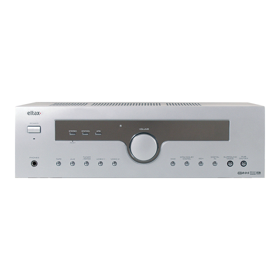
Page 11: Front Panel Information
1. POWER Turns the unit on/off. 2. STEREO Press this button to alternate between Stereo and Mono mode when listen to FM broadcast. 3. STATION When using the Tuner press this button to select a preset channel. 4. APS Allocates and memorizes radio stations automatically. -
Page 12: Rear Panel Information
REAR PANEL INFORMATION 1. AC CORD: Connect to the AC mains socket. 2. SPEAKERS: External speakers power output. (Refer to Speaker Connection section) 3. SUB LINE OUT: Pre-out for an active subwoofer. 4. S-VIDEO IN/OUT terminals: - DVD S-VIDEO IN: Connect an S-VIDEO cable to the S-VIDEO output terminal of a DVD player. - VIDEO-S IN: For connection of S-VIDEO cable to the output terminal of an external player. -
Page 13: Remote Control Unit
REMOTE CONTROL By using the provided remote control unit, this unit can be controlled from your listening position. To use the remote control unit, point it at the REMOTE SENSOR window of this unit. Notes: - Even if the remote control unit is operated within the effective range, remote control operation may be impossible if there are any obstacles between the unit and the remote control. -
Page 14: Remote Control Information
REMOTE CONTROL INFORMATION... - Page 15 Power Push this button to turn the unit into standby mode, push it again to turn off the unit. Mute Press this button to mute the sound, push again to cancel the mute function. Input Mode Select Coaxial, Optical or Analog Input mode in DVD, AV1 and AV2. Dimmer Press this button to set the brightness of the front panel display.
-
Page 16: Basic Operation 1
BASIC OPERATION 1 Press the POWER button to put this unit into Standby Mode. Press one of the source buttons to activate the unit. Select the desired source by pressing DVD, VIDEO 1, VIDEO 2, TUNER, AUX or TAPE. If you have selected DVD, VIDEO 1, VIDEO 2 (not TUNER, AUX or TAPE), press INPUT MODE, SURROUND MODE, DTS/DOLBY DIGITAL, STEREO, DOLBY PROLOGIC II or DIGITAL IN in accordance with the type of signal you are receiving and the sound output you require (for example, Dolby Pro Logic II if the DVD movie is an older "classic"... - Page 17 PLAYING VIDEO SOURCES Select DVD, VIDEO1, VIDEO 2 by pressing the corresponding button. Play the sound source corresponding to the source selected (for example, if you have selected DVD, press PLAY on your DVD player). The picture from the video source will be transmitted to the TV and the sound from the video source will be heard from the speakers. THE RADIO OPERATIONS Automatic Tuning Press the POWER button, then press the TUNER button to turn ON this unit.
-
Page 18: Radio Data System (Rds)
RADIO DATA SYSTEM (RDS) RDS is a method for the transmission of additional information from local radio stations (the system only operates for radio stations broadcasting in FM). Using RDS data you can see the name of the radio station, the name of the program and/or the type of program, all shown on the multi-function display (Note: RDS only functions when the local radio station includes the RDS transmission within its signal and when the signal is strong enough). -
Page 19: Speaker Configuration, Delay Time & Dynamic Range Control
SPEAKER CONFIGURATION, DELAY TIME & DYNAMIC RANGE CONTROL SPEAKER CONFIGURATION It is important to configure your speakers correctly in order to get the most from your AV Receiver. This versatile AV Receiver provides the flexibility to experience multi-channel surround sound without a center speaker. -
Page 20: Low Frequency Effect
TEST TONE Speaker Level balance Adjustment The test tone function is useful to adjust the relative volume between speakers in DOLBY DIGITAL or DOLBY PRO LOGIC II mode. Once the balance is set, you don’t have to change the balance as long as the speakers aren’t moved. -
Page 21: Available Surround Mode
SURROUND MODE The surround modes create a “live” atmosphere such as that experienced in movie theaters, discos, stadiums and concert halls. Select the appropriate surround mode according to the program source. (Note: Surround speakers are needed for DTS/DOLBY DIGITAL Dolby Pro Logic II surround modes to function). It is recommended to use a Center speaker when operating this unit in DTS/DOLBY DIGITAL/Dolby Pro Logic II surround modes. -
Page 22: Troubleshooting
Suggestion Check and reconnect the speakers to the correct output on the AVR-320 rear panel. Place this product as far as possible from electric devices which emit electrical interference. -
Page 23: Specifications
AUDIO SECTION Rated Power Output Output Terminals Total Harmonic Distortion Less than 0.05% at1/2 rated power output LINE INPUT Input Sensitivity/Impedance Frequency Response Tone Control Range Signal-Noise Ratio WOOFER OUTPUT Rated Output/Impedance Frequency Response FM TUNER SECTION Frequency Range Sensitivity Antenna Terminal MW TUNER SECTION Frequency Range... - Page 24 For further information please visit our website: www.eltax.com Itemno. 40129...
Need help?
Do you have a question about the AVR-320 and is the answer not in the manual?
Questions and answers