Table of Contents
Advertisement
Quick Links
Advertisement
Table of Contents

Related Manuals for Motorola SYMBOL LS7708


Summary of Contents for Motorola SYMBOL LS7708
- Page 1 Symbol LS7708 Product Reference Guide...
- Page 3 Symbol LS7708 Product Reference Guide 72E-69531-02 Revision A February 2007...
- Page 4 The software is provided strictly on an “as is” basis. All software, including firmware, furnished to the user is on a licensed basis. Motorola grants to the user a non-transferable and non-exclusive license to use each software or firmware program delivered hereunder (licensed program). Except as noted below, such license may not be assigned, sublicensed, or otherwise transferred by the user without prior written consent of Motorola.
-
Page 5: Revision History
Revision History Changes to the original manual are listed below: Change Date Description 72E-69531-01 9/2004 Initial release. 72E-69413-02 2/2007 Update service information, add parameter bar codes for Bookland ISBN, new UPC supplemental decode options, report software version, report MIMIC version, report Synapse cable... -
Page 7: Table Of Contents
Contents About This Guide Introduction ................xv Chapter Descriptions . - Page 8 Symbol LS7708 Product Reference Guide Active Scan Area ............... . .2-3 Scanning Bar Codes .
- Page 9 Contents vii Ignore Unknown Characters ............5-14 Keystroke Delay .
- Page 10 Symbol LS7708 Product Reference Guide Convert Case............... .7-22 ASCII Character Set .
- Page 11 Contents ix Chapter 13. Symbologies Introduction................13-3 Scanning Sequence Examples .
- Page 12 Symbol LS7708 Product Reference Guide Enable/Disable Interleaved 2 of 5 ............13-67 Set Lengths for Interleaved 2 of 5 .
- Page 13 Contents xi UPC/EAN................C-3 UPC-A, 100 % .
- Page 14 Symbol LS7708 Product Reference Guide...
-
Page 15: About This Guide
About This Guide Introduction ................xv Chapter Descriptions . - Page 16 Symbol LS7708 Product Reference Guide...
-
Page 17: Introduction
Introduction The Symbol LS7708 Product Reference Guide provides general instructions for setting up, operating, maintaining, and troubleshooting the Symbol LS7708 scanner. Chapter Descriptions • Chapter 1, Getting Started provides a product overview and unpacking instructions. • Chapter 2, Scanning describes parts of the scanner, beeper and LED definitions, and how to use the scanner in hand-held and hands-free modes. -
Page 18: Notational Conventions
Global Customer Interaction Center will provide specific directions. Motorola is not responsible for any damages incurred during shipment if the approved shipping container is not used. Shipping the units improperly can possibly void the warranty. If the original shipping container was Note not kept, contact Motorola to have another sent. - Page 19 Getting Started Introduction ................1-3 Unpacking the Scanner .
- Page 20 Symbol LS7708 Product Reference Guide...
-
Page 21: Chapter 1. Getting Started
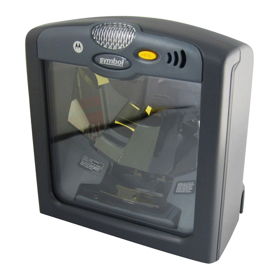
Getting Started 1-3 Introduction The Symbol LS7708 scanner provides multiple scan patterns that support high throughput applications at the point of sale (POS). The rastering, 120-line, omni-directional scan pattern provides fast, intuitive, hands-free scanning. The scanner reads all retail symbologies and has multi-interface capability to interface to all popular POS devices. The scanner mounts on a counter top or vertical surface such as a wall. -
Page 22: Unpacking The Scanner
• Scanner • Mounting bracket and hardware • LS7708 Quick Reference Guide (p/n 72-69530-xx) • CD containing 123Scan software and Symbol LS7708 Product Reference Guide (p/n 72-69531-xx). The package may also include the following: • Power supply and cable • RS-232C host interface cable •... -
Page 23: Input/Output Ports
Getting Started 1-5 Input/Output Ports The bottom of the scanner includes the ports in Figure 1-2 RS-232 Aux Port Power Port Secondary Scanner Host Port (Synapse) Port EAS Interlock Port (Behind Label) Figure 1-2. Scanner Ports Power Port. When external power is required, the input to this port is 5V @ 500 mA maximum, 390 mA nominal, with no peripherals, 5V @ 1.5A maximum with peripherals. -
Page 24: Setting Up The Scanner
Symbol LS7708 Product Reference Guide Setting Up the Scanner Power Options Depending on the peripherals used, the scanner receives power from one of two sources: • Via the host through the host cable: If the host can supply 500mA of power, the host cable is less than 8.5’ long, and there are no peripheral devices in the configuration. - Page 25 Getting Started 1-7 RS-232 Aux Cable EAS Interlock Cable Host Interface Power Cable Cable Scanner Host Cable EAS Interlock Power RS-232 Aux Secondary Scanner (Synapse) Figure 1-3. Scanner Connections Different hosts require different cables. The connectors illustrated in each host chapter are examples only. Connectors may be different from those illustrated, but the steps to connect the scanner are the same.
-
Page 26: Routing Cables
Symbol LS7708 Product Reference Guide Routing Cables The scanner case has several channels to route the outgoing cables so that they are organized and don’t hinder the scanner’s placement (see Figure 1-1 Figure 1-3). After placing the cable connectors in the appropriate scanner ports, route the cables through the nearest channel. -
Page 27: Configuring The Scanner
Getting Started 1-9 Configuring the Scanner To configure the scanner, use the bar codes in this manual, or use the 123Scan configuration program. Refer to Chapter 4, User Preferences for information about programming the scanner using bar code menus. Refer to Chapter 12, 123Scan to configure the scanner using this configuration program. -
Page 28: Mounting The Scanner To A Surface
1-10 Symbol LS7708 Product Reference Guide Mounting the Scanner to a Surface The Symbol LS7708 is designed to sit on top of a counter or be mounted to a wall. The back of the scanner has a slot that accepts a mounting bracket to secure it to the mounting surface. - Page 29 Getting Started 1-11 5. When the bracket is flat against the scanner bottom, release pressure so that the feet slide forward into the front of the scanner. Attached Configuration To attach the scanner to a mounting surface: 1. Determine the location for mounting the scanner. 2.
- Page 30 1-12 Symbol LS7708 Product Reference Guide 6. Insert screws through the holes and fasten to the mounting surface. 7. Align the slot at the back of the scanner with the plastic tab on the mounting bracket. 8. Angle the scanner slightly to allow the bracket hook to slide into the slot.
-
Page 31: Detaching The Scanner From The Mounting Bracket
Getting Started 1-13 Detaching the Scanner from the Mounting Bracket To detach the scanner: 1. Grasp the scanner firmly on both sides. 2. Squeeze the back of the scanner slightly while pushing the scanner in the direction of the slot on the back. 3. - Page 32 1-14 Symbol LS7708 Product Reference Guide...
- Page 33 Scanning Introduction ................2-3 Active Scan Area .
- Page 34 Symbol LS7708 Product Reference Guide...
-
Page 35: Introduction
Scanning 2-3 Introduction This chapter covers the techniques involved in scanning bar codes, beeper and LED definitions, and general instructions and tips about scanning. Refer to Chapter 1, Getting Started for information on scanner components, and connecting host cables and the power supply. - Page 36 Symbol LS7708 Product Reference Guide Figure 2-2. Scanning a Bar Code - Swipe Method Figure 2-3. Scanning a Bar Code - Presentation Method 4. Upon successful decode, the scanner beeps and the green LED flashes. For more information on beeper definitions, see Table 2-1.
-
Page 37: Beeper Definitions
Scanning 2-5 Beeper Definitions The scanner communicates by emitting different beeper sequences. Table 2-1 defines beeper sequences that occur during normal scanning and while programming the scanner. Table 2-1. Standard Beeper Definitions Beeper Sequence Indication Standard Use 3 short high beeps Power up. -
Page 38: Selecting Beeper Volume
Symbol LS7708 Product Reference Guide Table 2-1. Standard Beeper Definitions Beeper Sequence Indication RS-232 Auxiliary Port only 1 short high beep A complete block of data was received and sent to the host, either due to a carriage return or because the two-second serial response timeout has elapsed. -
Page 39: Decode Zone
Scanning 2-7 Decode Zone Figure 2-4 illustrates the area in which the scanner recognizes bar codes. Figure 2-4. Symbol LS7708 Decode Zone... -
Page 40: Integrated Electronic Article Surveillance (Eas)
The deactivation range is mapped suitable to the scanning range, so both can be accomplished almost simultaneously. The interlock feature requires a good decode signal to activate the EAS system. Do not attempt to activate the interlock feature. Activation instructions are for a Motorola qualified technician only. -
Page 41: Introduction
Maintenance and Technical Specifications Introduction ................3-3 Maintenance . - Page 42 Symbol LS7708 Product Reference Guide...
-
Page 43: Chapter 3. Maintenance And Technical Specifications
Maintenance and Technical Specifications 3-3 Introduction This chapter covers suggested scanner maintenance, troubleshooting, technical specifications, and signal descriptions (pinouts). Maintenance Cleaning the exit window is the only maintenance required. A dirty window can affect scanning accuracy. • Do not allow abrasive material to touch the window. •... -
Page 44: Replacing The Scanner Window
Symbol LS7708 Product Reference Guide Replacing the Scanner Window To replace the scanner window: 1. Reach under the lip of the front panel and lift it away from the scanner. Front Panel Figure 3-1. Removing the Front Panel 2. Unfasten the screws behind the panel that secure the window frame.) -
Page 45: Technical Specifications
Maintenance and Technical Specifications 3-5 Glass Figure 3-3. Removing and Replacing the Window Glass 5. Insert a new, clean exit window. 6. Tilt the window frame back into position. 7. Secure the window frame to the scanner using two screws. 8. -
Page 46: Troubleshooting
Symbol LS7708 Product Reference Guide Troubleshooting Problem Possible Causes Possible Solutions The omni-line scan pattern does not No power to the scanner. Ensure the host has power and is on. If the scanner uses a separate display when following the directions for power supply, ensure it’s connected to a working AC outlet. -
Page 47: Technical Specifications
Maintenance and Technical Specifications 3-7 Technical Specifications Table 3-1. Technical Specifications Item Description Physical Characteristics Dimensions: Without stand: Height 6.3 in. (16 cm) Width 5.98 in. (15.2 cm) Depth 3.73 in. (9.5 cm) Weight Scanner only: 2.04 lbs. (925 g) Power Source Power drawn from host terminal or external power supply;... - Page 48 Symbol LS7708 Product Reference Guide Table 3-1. Technical Specifications (Continued) Item Description EAS Support Checkpoint Electronic Article Surveillance Antenna (EAS) Included Sensormatic - Contact Product Management Regulatory Electrical Safety Certified to UL60950, CSA C22.2 No.60950, EN60950 Laser Safety CDRH Class IIa Laser Product...
-
Page 49: Scanner Signal Descriptions
Maintenance and Technical Specifications 3-9 Scanner Signal Descriptions Host RS-232 Power Synapse Port Aux Port Interlock Port Port Port Pin 1 Pin 1 Pin 1 Pin 10 Pin 10 Pin 6 Host RS-232 Hand-Held Port Auxiliary Port Scanner Port Interface cable modular connector Figure 3-4. - Page 50 3-10 Symbol LS7708 Product Reference Guide The signal descriptions in Table 3-2 apply to the connector on the scanner and are for reference only. Table 3-2. Scanner/Host Signal Pin-outs Symbol LS7708 Keyboard Synapse RS-232 Wedge Download Reserved SynClock Reserved Reserved...
- Page 51 Maintenance and Technical Specifications 3-11 Table 3-4. Hand-Held Scanner Port Pinouts Pin 1 Pin 2 Pin 3 Pin 4 Pin 5 Pin 6 SYNDATA SYNCLK Table 3-5. EAS Interlock Port Pinouts Pin 1 Pin 2 Pin 3 Pin 4 INTERLOCK...
- Page 52 3-12 Symbol LS7708 Product Reference Guide...
- Page 53 User Preferences Introduction ................4-3 Scanning Sequence Examples .
- Page 54 Symbol LSSymbol LS7708 Product Reference Guide...
-
Page 55: Chapter 4. User Preferences
User Preferences 4-3 Introduction The scanner can be programmed to perform various functions or activate different features. This chapter describes each user preference feature and provides the programming bar codes necessary for selecting these features for the scanner. Before programming, follow the instructions in Chapter 1, Getting Started. - Page 56 Symbol LSSymbol LS7708 Product Reference Guide Table 4-1. User Preferences Default Table Parameter Default Page Number User Preferences Set Default Parameter All Defaults Beeper Tone Medium Beeper Volume High Beep After Good Decode Enable Low Power Mode Low Power Blink Mode 4-10 Scan Pattern Mode Rastering...
-
Page 57: User Preferences
User Preferences 4-5 User Preferences Scanning parameter setting bar codes with the primary scanner also changes settings on the auxiliary scanner. Note Set Default Parameter Scanning this bar code returns all parameters to the default values listed in Table A-1 on page A-1. - Page 58 Symbol LSSymbol LS7708 Product Reference Guide Beeper Tone (continued) Medium Frequency High Frequency...
-
Page 59: Beeper Volume
User Preferences 4-7 Beeper Volume To select a beeper volume, scan one of the following bar codes. Low Beeper Volume Low Beeper Volume Medium Beeper Volume Medium Beeper Volume... - Page 60 Symbol LSSymbol LS7708 Product Reference Guide High Beeper Volume High Beeper Volume...
-
Page 61: Beep After Good Decode
User Preferences 4-9 Beep After Good Decode Scan a bar code below to select whether or not the scanner beeps after a good decode. If Do Not Beep After Good Decode is selected, the beeper still operates during parameter menu scanning and indicates error conditions. Beep After Good Decode (Enable) Do Not Beep After Good Decode... -
Page 62: Low Power Mode
4-10 Symbol LSSymbol LS7708 Product Reference Guide Low Power Mode After a period of inactivity, the scanner enters a reduced power mode. This parameter controls how aggressively power is conserved, and therefore determines the method of waking the scanner up. Low Power Blink Selecting Low Power Blink Mode causes the scanner (after a period of inactivity) to blink the laser infrequently to save power. -
Page 63: Scan Pattern Mode
User Preferences 4-11 Scan Pattern Mode The Symbol LS7708 has a very aggressive scan pattern that is both omnidirectional and raster. To select a static omnidirectional pattern, scan the Omnidirectional Pattern bar code to change the scan pattern. Rastering Omnidirectional Pattern Omnidirectional Pattern... -
Page 64: Timeout Between Decodes
4-12 Symbol LSSymbol LS7708 Product Reference Guide Timeout Between Decodes Timeout Between Decodes, Same Symbol This parameter sets the minimum time between decodes of the same symbol. It is programmable in 0.1-second increments from 0.0 to 9.9 seconds. Setting this above 0.4 seconds is recommended. The default for this parameter is 0.6 seconds. Scan the bar code below to select a new timeout. -
Page 65: Time Delay To Low Power Mode
User Preferences 4-13 Time Delay to Low Power Mode This parameter sets the time that the scanner remains active after any scanning activity. Depending on the selection, the scanner enters a sleep mode 15, 30, 60, or 90 minutes after the last attempted decode. To awaken the scanner, see Low Power Mode on page 4-10. - Page 66 4-14 Symbol LSSymbol LS7708 Product Reference Guide Time Delay to Low Power Mode (continued) 60 Minutes 90 Minutes...
-
Page 67: Linear Upc/Ean Decode
User Preferences 4-15 Linear UPC/EAN Decode This option applies to code types containing two adjacent blocks (e.g., UPC-A, EAN-8, EAN-13). When enabled, a bar code is transmitted only when both the left and right blocks are successfully decoded within one laser scan. Enable this option when bar codes are in proximity to each other. -
Page 68: Upc Half Block Stitching
4-16 Symbol LSSymbol LS7708 Product Reference Guide UPC Half Block Stitching This parameter enables UPC Half Block Stitching for the Symbol LS7708 omnidirectional scanner only. *Enable UPC Half Block Stitching Disable UPC Half Block Stitching... -
Page 69: Eas Interlock
User Preferences 4-17 EAS Interlock Enable EAS Interlock When enabled, the EAS tag is de-activated only when the associated bar code is decoded. Enable EAS Interlock Disable EAS Interlock When disabled (default), the EAS tag is de-activated independently of any bar code scanning. *Disable EAS Interlock... - Page 70 4-18 Symbol LSSymbol LS7708 Product Reference Guide...
- Page 71 Keyboard Wedge Interface Introduction ................5-3 Connecting a Keyboard Wedge Interface .
- Page 72 Symbol LS7708 Product Reference Guide...
-
Page 73: Chapter 5. Keyboard Wedge Interface
Keyboard Wedge Interface 5-3 Introduction This chapter provides information for setting up the scanner with a Keyboard Wedge interface. Use this interface type to attach the scanner between the keyboard and host computer. The scanner translates bar code data into keystrokes which the host computer accepts as if they originate from the keyboard. -
Page 74: Connecting A Keyboard Wedge Interface
Symbol LS7708 Product Reference Guide Connecting a Keyboard Wedge Interface To connect the Keyboard Wedge configuration (see Figure 5-1): Host Port Keyboard Power Port Host Keyboard Port Figure 5-1. Keyboard Wedge Connection Without Peripherals - Power Supplied Externally 1. Switch off the host and unplug the keyboard connector. - Page 75 Keyboard Wedge Interface 5-5 Hand-Held Scanner RS-232 Auxiliary Device Host Port Power Port Keyboard Host Power Supply Figure 5-2. Keyboard Wedge Connection with Peripherals - Power Supplied Externally...
-
Page 76: Keyboard Wedge Default Parameters
Symbol LS7708 Product Reference Guide Keyboard Wedge Default Parameters Table 5-1 lists the defaults for Keyboard Wedge host parameters. To change any option, scan the appropriate bar code(s) beginning Keyboard Wedge Host Types on page 5-7. Scanning parameter setting bar codes with the primary scanner also changes settings on the auxiliary scanner. -
Page 77: Keyboard Wedge Host Types
Keyboard Wedge Interface 5-7 Keyboard Wedge Host Types Select the keyboard wedge host by scanning one of the following bar codes. IBM PC/AT & IBM PC Compatibles IBM PS/2 (Model 30) User selection is required to configure this interface and this is the most common selection. Note... - Page 78 Symbol LS7708 Product Reference Guide Keyboard Wedge Host Types (continued) IBM AT NOTEBOOK NCR 7052...
-
Page 79: Keyboard Wedge Country Types (Country Codes)
Keyboard Wedge Interface 5-9 Keyboard Wedge Country Types (Country Codes) Scan the bar code corresponding to the keyboard type. If the particular keyboard type is not listed, see Alternate Numeric Keypad Emulation on page 5-18. North American German Windows... - Page 80 5-10 Symbol LS7708 Product Reference Guide Keyboard Wedge Country Types (continued) French Windows French Canadian Win 95/98...
- Page 81 Keyboard Wedge Interface 5-11 Keyboard Wedge Country Types (continued) French Canadian Windows XP/2000 Spanish Windows...
- Page 82 5-12 Symbol LS7708 Product Reference Guide Keyboard Wedge Country Types (continued) Italian Windows Swedish Windows...
- Page 83 Keyboard Wedge Interface 5-13 Keyboard Wedge Country Types (continued) UK English Windows Japanese Windows...
-
Page 84: Ignore Unknown Characters
5-14 Symbol LS7708 Product Reference Guide Keyboard Wedge Country Types (continued) Brazilian/Portuguese Windows Ignore Unknown Characters Unknown characters are characters the host does not recognize. When Send Bar Codes With Unknown Characters is selected, all bar code data is sent except for unknown characters, and no error beeps sound on the scanner. When Do Not Send Bar Codes With Unknown Characters is selected, bar code data is sent up to the first unknown character and then four (error) beeps sound on the scanner. -
Page 85: Keystroke Delay
Keyboard Wedge Interface 5-15 Ignore Unknown Characters (continued) Do Not Send Bar Codes With Unknown Characters Keystroke Delay This is the delay in milliseconds between emulated keystrokes. Scan a bar code below to increase the delay when hosts require a slower transmission of data. - Page 86 5-16 Symbol LS7708 Product Reference Guide Keystroke Delay (continued) Medium Delay (20 msec) Long Delay (40 msec)
-
Page 87: Intra-Keystroke Delay
Keyboard Wedge Interface 5-17 Intra-Keystroke Delay Enable this to insert an additional delay between each emulated key depression and release. This sets the Keystroke Delay parameter to a minimum of 5 msec as well. Enable Disable... -
Page 88: Alternate Numeric Keypad Emulation
5-18 Symbol LS7708 Product Reference Guide Alternate Numeric Keypad Emulation This allows emulation of most other country keyboard types not listed in Keyboard Wedge Country Types (Country Codes) on page 5- in a Microsoft operating system environment. Enable Alternate Numeric Keypad... -
Page 89: Caps Lock On
Keyboard Wedge Interface 5-19 Caps Lock On When enabled, the scanner emulates keystrokes as if the Caps Lock key is always pressed. Enable Caps Lock On Disable Caps Lock On... -
Page 90: Caps Lock Override
5-20 Symbol LS7708 Product Reference Guide Caps Lock Override When enabled, on AT or AT Notebook hosts, the keyboard ignores the state of the Caps Lock key. Therefore, an ‘A’ in the bar code is sent as an ‘A’ regardless of the state of the keyboard’s Caps Lock key. -
Page 91: Convert Wedge Data
Keyboard Wedge Interface 5-21 Convert Wedge Data When enabled, the scanner converts all bar code data to the selected case. Convert to Upper Case Convert to Lower Case... - Page 92 5-22 Symbol LS7708 Product Reference Guide Convert Wedge Data (continued) No Convert...
-
Page 93: Function Key Mapping
Keyboard Wedge Interface 5-23 Function Key Mapping ASCII values under 32 are normally sent as a control-key sequences (see Table 7-2 on page 7-24). Enable this parameter to send the keys in bold in place of the standard key mapping. Items that do not have a bold entry remain the same whether or not this parameter is enabled. -
Page 94: Fn1 Substitution
5-24 Symbol LS7708 Product Reference Guide FN1 Substitution Enable this to replace any FN1 characters in an EAN 128 bar code with a selected Key Category and Key Value (see FN1 Substitution Values on page 14-6). Enable *Disable... -
Page 95: Send Make Break
Keyboard Wedge Interface 5-25 Send Make Break When enabled, the scan codes for releasing a key are not sent. *Send Make and Break Scan Codes Send Make Scan Code Only... -
Page 96: Onkeyboard Maps
5-26 Symbol LS7708 Product Reference Guide OnKeyboard Maps The following keyboard maps are provided for prefix/suffix keystroke parameters. To program the prefix/suffix values, see the bar codes on page 14-5. 7014 5001 5002 5003 5004 5005 5006 5007 5008 5009... - Page 97 Keyboard Wedge Interface 5-27 OnKeyboard Maps (continued) 1068 1067 1066 1070 1071 1065 1069 1075 1072 1073 1074 1076 1077 1078 1082 1079 1080 1083 1084 1085 1081 5002 1045 5013 1086 5001 5011 5003 5014 5015 1087 5004 5005 5006 1043 5016...
-
Page 98: Ascii Character Set
5-28 Symbol LS7708 Product Reference Guide ASCII Character Set Code 39 Full ASCII interprets the bar code special character ($ + % /) preceding a Code 39 character and assigns an ASCII character value to the pair. For example, when Code 39 Full ASCII is enabled and a +B is Note scanned, it is interpreted as b,%J as ?, and %V as @. - Page 99 Keyboard Wedge Interface 5-29 Table 5-2. Keyboard Wedge ASCII Character Set (Continued) Full ASCII Code 39 ASCII Value Encoded Character Keystroke 1029 CTRL ] 1030 CTRL 6 1031 CTRL - 1032 Space Space 1033 1034 “ 1035 1036 1037 1038 &...
- Page 100 5-30 Symbol LS7708 Product Reference Guide Table 5-2. Keyboard Wedge ASCII Character Set (Continued) Full ASCII Code 39 ASCII Value Encoded Character Keystroke 1062 > 1063 1064 1065 1066 1067 1068 1069 1070 1071 1072 1073 1074 1075 1076 1077...
- Page 101 Keyboard Wedge Interface 5-31 Table 5-2. Keyboard Wedge ASCII Character Set (Continued) Full ASCII Code 39 ASCII Value Encoded Character Keystroke 1095 1096 ‘ 1097 1098 1099 1100 1101 1102 1103 1104 1105 1106 1107 1108 1109 1110 1111 1112 1113 1114 1115...
- Page 102 5-32 Symbol LS7708 Product Reference Guide Table 5-3. Keyboard Wedge ALT Key Character Set ALT Keys Keystroke 2065 ALT A 2066 ALT B 2067 ALT C 2068 ALT D 2069 ALT E 2070 ALT F 2071 ALT G 2072 ALT H...
- Page 103 Keyboard Wedge Interface 5-33 Table 5-4. Keyboard Wedge GUI Key Character Set GUI Keys Keystrokes 3000 Right Control Key 3048 GUI 0 3049 GUI 1 3050 GUI 2 3051 GUI 3 3052 GUI 4 3053 GUI 5 3054 GUI 6 3055 GUI 7 3056...
- Page 104 5-34 Symbol LS7708 Product Reference Guide Table 5-5. Keyboard Wedge F Key Character Set F Keys Keystroke 5001 5002 5003 5004 5005 5006 5007 5008 5009 5010 5011 5012 5013 5014 5015 5016 5017 5018 5019 5020 5021 5022 5023...
- Page 105 Keyboard Wedge Interface 5-35 Table 5-6. Keyboard Wedge Numeric Keypad Character Set Numeric Keypad Keystroke 6042 6043 6044 undefined 6045 6046 6047 6048 6049 6050 6051 6052 6053 6054 6055 6056 6057 6058 Enter 6059 Num Lock...
- Page 106 5-36 Symbol LS7708 Product Reference Guide Table 5-7. Keyboard Wedge Extended Keypad Character Set Extended Keypad Keystroke 7001 Break 7002 Delete 7003 Pg Up 7004 7005 Pg Dn 7006 Pause 7007 Scroll Lock 7008 Backspace 7009 7010 Print Screen 7011...
- Page 107 RS-232 Host Interface Introduction ................6-3 Connecting an RS-232 Interface .
- Page 108 Symbol LS7708 Product Reference Guide...
-
Page 109: Introduction
RS-232 Host Interface 6-3 Introduction This chapter provides information for setting up the scanner with an RS-232 host. Use the RS-232 interface to attach the scanner to point-of-sale devices, host computers, or other devices with an available RS-232 port (e.g., com port). This scanner uses TTL RS-232 levels to interface with all PC's without additional hardware. -
Page 110: Connecting An Rs-232 Interface
Symbol LS7708 Product Reference Guide Connecting an RS-232 Interface There are several possible configurations for connecting to an RS-232 host. The scanner connects directly to the host computer. Host Port Host Serial Port To EAS (optional) Figure 6-1. RS-232 Connection Without Peripherals - Power Supplied Externally... - Page 111 RS-232 Host Interface 6-5 Hand-Held Scanner Host Port RS-232 Auxiliary Device Power Port Host Serial Port To EAS (optional) Power Supply Figure 6-2. RS-232 Connection with Peripherals - Power Supplied Externally 1. Connect the RS-232 interface cable to the host port of the scanner. 2.
-
Page 112: Rs-232 Default Parameters
Symbol LS7708 Product Reference Guide RS-232 Default Parameters Table 6-1 lists the defaults for RS-232 host parameters. To change any option, scan the appropriate bar code(s) beginning in RS-232 Host Parameters on page 6-7. Scanning parameter setting bar codes with the primary scanner also changes settings on the auxiliary scanner. -
Page 113: Rs-232 Host Parameters
RS-232 Host Interface 6-7 RS-232 Host Parameters Various RS-232 hosts are set up with their own parameter default settings. Selecting the ICL, Fujitsu, Wincor-Nixdorf Mode A, Wincor-Nixdorf Mode B, Olivetti, Omron, or terminal sets the defaults listed in Table 6-2. Table 6-2. - Page 114 Symbol LS7708 Product Reference Guide Selecting the ICL, Fujitsu, Wincor-Nixdorf Mode A, Wincor-Nixdorf Mode B, OPOS, JPOS terminal enables the transmission of code ID characters listed in Table 6-3. These code ID characters are not programmable and are separate from the Transmit Code ID feature.
-
Page 115: Rs-232 Host Types
RS-232 Host Interface 6-9 RS-232 Host Types To select an RS-232 host interface, scan one of the following bar codes. Standard RS-232 ICL RS-232 User selection is required to configure this interface and this is the most common selection. Note... - Page 116 6-10 Symbol LS7708 Product Reference Guide RS-232 Host Types (continued) Wincor-Nixdorf RS-232 Mode A Wincor-Nixdorf RS-232 Mode B...
- Page 117 RS-232 Host Interface 6-11 RS-232 Host Types (continued) Fujitsu RS-232 Olivetti ORS4500...
- Page 118 6-12 Symbol LS7708 Product Reference Guide RS-232 Host Types (continued) Omron OPOS/JPOS...
-
Page 119: Baud Rate
RS-232 Host Interface 6-13 Baud Rate Baud rate is the number of bits of data transmitted per second. Select the baud rate setting to match the baud rate setting of the host device. Otherwise, data may not reach the host device or may reach it in distorted form. Baud Rate 600 Baud Rate 1200... - Page 120 6-14 Symbol LS7708 Product Reference Guide Baud Rate (continued) Baud Rate 2400 Baud Rate 4800...
- Page 121 RS-232 Host Interface 6-15 Baud Rate (continued) Baud Rate 9600 Baud Rate 19,200...
- Page 122 6-16 Symbol LS7708 Product Reference Guide Baud Rate (continued) Baud Rate 38,400...
-
Page 123: Parity
RS-232 Host Interface 6-17 Parity A parity check bit is the most significant bit of each ASCII coded character. Select the parity type according to host device requirements. Select Odd parity and the parity bit value is set to 0 or 1, based on data, to ensure that an odd number of 1 bits are contained in the coded character. - Page 124 6-18 Symbol LS7708 Product Reference Guide Parity (continued) Select Mark parity and the parity bit is always 1. Mark Select Space parity and the parity bit is always 0. Space...
- Page 125 RS-232 Host Interface 6-19 Parity (continued) Select None when no parity bit is required. None...
-
Page 126: Check Receive Errors
6-20 Symbol LS7708 Product Reference Guide Check Receive Errors Select whether or not the parity, framing, and overrun of received characters are checked. The parity value of received characters is verified against the parity parameter selected above. Check For Received Errors... -
Page 127: Hardware Handshaking
RS-232 Host Interface 6-21 Hardware Handshaking The data interface consists of an RS-232 port designed to operate either with or without the hardware handshaking lines, Request to Send (RTS), and Clear to Send (CTS). If Standard RTS/CTS handshaking is not selected, scan data is transmitted as it becomes available. If Standard RTS/CTS handshaking is selected, scan data is transmitted according to the following sequence: •... - Page 128 6-22 Symbol LS7708 Product Reference Guide Standard RTS/CTS Scan the bar code below to select Standard RTS/CTS Hardware Handshaking. Standard RTS/CTS RTS/CTS Option 1 When RTS/CTS Option 1 is selected, the scanner asserts RTS before transmitting and ignores the state of CTS. The scanner de- asserts RTS when the transmission is complete.
- Page 129 RS-232 Host Interface 6-23 RTS/CTS Option 2 When Option 2 is selected, RTS is always high or low (user-programmed logic level). However, the scanner waits for CTS to be asserted before transmitting data. If CTS is not asserted within 2 seconds (default), the scanner issues an error indication and discards the data.
-
Page 130: Software Handshaking
6-24 Symbol LS7708 Product Reference Guide Software Handshaking This parameter offers control of the data transmission process in addition to, or instead of, that offered by hardware handshaking. There are five options. If Software Handshaking and Hardware Handshaking are both enabled, Hardware Handshaking takes precedence. - Page 131 RS-232 Host Interface 6-25 When this option is selected, the scanner waits for an ENQ character from the host before transmitting data. If an ENQ is not received within the Host Serial Response Time-out, the scanner issues an error indication and discards the data. The host must transmit an ENQ character at least every Host Serial Response Time-out to prevent transmission errors.
-
Page 132: Host Serial Response Time-Out
6-26 Symbol LS7708 Product Reference Guide XON/XOFF An XOFF character turns the scanner transmission off until the scanner receives an XON character. There are two situations for XON/ XOFF: • XOFF is received before the scanner has data to send. When the scanner has data to send, it waits up to 2 seconds for an XON character before transmission. - Page 133 RS-232 Host Interface 6-27 Host Serial Response Time-out (continued) Low: 2.5 Sec Medium: 5 Sec...
- Page 134 6-28 Symbol LS7708 Product Reference Guide Host Serial Response Time-out (continued) High: 7.5 Sec Maximum: 9.9 Sec...
-
Page 135: Rts Line State
RS-232 Host Interface 6-29 RTS Line State This parameter sets the idle state of the Serial Host RTS line. Scan a bar code below to select Low RTS or High RTS line state. Host: Low RTS Host: High RTS... -
Page 136: Stop Bit Select
6-30 Symbol LS7708 Product Reference Guide Stop Bit Select The stop bit(s) at the end of each transmitted character marks the end of transmission of one character and prepares the receiving device for the next character in the serial data stream. The number of stop bits selected (one or two) depends on the number the receiving terminal is programmed to accommodate. -
Page 137: Data Bits
RS-232 Host Interface 6-31 Data Bits This parameter allows the scanner to interface with devices requiring a 7-bit or 8-bit ASCII protocol. 7-Bit 8-Bit... -
Page 138: Beep On
6-32 Symbol LS7708 Product Reference Guide Beep on <BEL> When this parameter is enabled, the scanner issues a beep when a <BEL> character is detected on the RS-232 serial line. <BEL> is issued to gain a user's attention to an illegal entry or other important event. -
Page 139: Intercharacter Delay
RS-232 Host Interface 6-33 Intercharacter Delay This parameter specifies the intercharacter delay inserted between character transmissions. Minimum: 0 msec Low: 25 msec... - Page 140 6-34 Symbol LS7708 Product Reference Guide Intercharacter Delay (continued) Medium: 50 msec High: 75 msec...
-
Page 141: Nixdorf Beep/Led Options
RS-232 Host Interface 6-35 Intercharacter Delay (continued) Maximum: 99 msec Nixdorf Beep/LED Options When Nixdorf Mode B is selected, this indicates when the scanner should beep and turn on its LED after a decode. *Normal Operation (Beep/LED immediately after decode) - Page 142 6-36 Symbol LS7708 Product Reference Guide Nixdorf Beep/LED Options (continued) Beep/LED After Transmission Beep/LED After CTS Pulse...
-
Page 143: Ignore Unknown Characters
RS-232 Host Interface 6-37 Ignore Unknown Characters Unknown characters are characters the host does not recognize. When Send Bar Codes With Unknown Characters is selected, all bar code data is send except for unknown characters, and no error beeps sound on the scanner. When Do Not Send Bar Codes With Unknown Characters is selected, bar code data is sent up to the first unknown character and then four (error) beeps sound on the scanner. -
Page 144: Ascii / Character Set
6-38 Symbol LS7708 Product Reference Guide ASCII / Character Set The values in Table 6-4 can be assigned as prefixes or suffixes for ASCII character data transmission. Table 6-4. ASCII Character Set Full ASCII ASCII Value Code 39 Encode Character... - Page 145 RS-232 Host Interface 6-39 Table 6-4. ASCII Character Set Full ASCII ASCII Value Code 39 Encode Character ASCII Character 1033 1034 “ 1035 1036 1037 1038 & 1039 ‘ 1040 1041 1042 1043 1044 1045 1046 1047 1048 1049 1050 1051 1052 1053...
- Page 146 6-40 Symbol LS7708 Product Reference Guide Table 6-4. ASCII Character Set Full ASCII ASCII Value Code 39 Encode Character ASCII Character 1068 1069 1070 1071 1072 1073 1074 1075 1076 1077 1078 1079 1080 1081 1082 1083 1084 1085 1086...
- Page 147 RS-232 Host Interface 6-41 Table 6-4. ASCII Character Set Full ASCII ASCII Value Code 39 Encode Character ASCII Character 1103 1104 1105 1106 1107 1108 1109 1110 1111 1112 1113 1114 1115 1116 1117 1118 1119 1120 1121 1122 1123 1124 1125 1126...
- Page 148 6-42 Symbol LS7708 Product Reference Guide...
- Page 149 USB Interface Introduction ................7-3 Connecting a USB Interface .
- Page 150 Symbol LS7708 Product Reference Guide...
-
Page 151: Chapter 7. Usb Interface
USB Interface 7-3 Introduction This chapter provides information on setting up the scanner with a USB host. The scanner attaches directly to a USB host computer. If there are no peripherals included in the configuration and the host cable is less than 8.5’ long, the host can power the scanner through the interface cable. - Page 152 Symbol LS7708 Product Reference Guide Host Port Host To EAS (optional) Figure 7-1. USB Connection Without Peripherals - Host Supplies Power...
- Page 153 USB Interface 7-5 Hand-Held Scanner Host Port RS-232 Auxiliary Device Power Port Host Power Supply To EAS (optional) Figure 7-2. USB Connection With Peripherals - Power Supplied Externally To set up the scanner: 1. Connect the USB interface cable to the host port of the scanner. 2.
-
Page 154: Usb Default Parameters
Symbol LS7708 Product Reference Guide USB Default Parameters Table 7-1 lists the defaults for USB host parameters. To change any option, scan the appropriate bar code(s) beginning in USB Host Parameters on page 7-7. Scanning parameter setting bar codes with the primary scanner also changes settings on the auxiliary scanner. -
Page 155: Usb Host Parameters
USB Interface 7-7 USB Host Parameters USB Device Type Select the desired USB device type. When changing USB Device Types, the scanner automatically restarts and issues the standard startup beep sequences. Note *HID Keyboard Emulation IBM Table Top USB... - Page 156 Symbol LS7708 Product Reference Guide USB Device Type (continued) IBM Hand-Held USB OPOS...
-
Page 157: Usb Country Keyboard Types (Country Codes)
USB Interface 7-9 USB Country Keyboard Types (Country Codes) Scan the bar code corresponding to the keyboard type. This setting applies only to the USB HID Keyboard Emulation device. When changing Country Selection, the scanner automatically restarts and issues the standard startup beep sequences. - Page 158 7-10 Symbol LS7708 Product Reference Guide USB Country Keyboard Types (continued) German, Windows French Canadian, Windows...
- Page 159 USB Interface 7-11 USB Country Keyboard Types (continued) French Canadian, Windows 2000/XP Spanish (Traditional), Windows...
- Page 160 7-12 Symbol LS7708 Product Reference Guide USB Country Keyboard Types (continued) Italian, Windows Swedish, Windows...
- Page 161 USB Interface 7-13 USB Country Keyboard Types (continued) UK English, Windows Japanese, Windows (ASCII)
-
Page 162: Usb Keystroke Delay
7-14 Symbol LS7708 Product Reference Guide USB Country Keyboard Types (continued) Portuguese-Brazilian, Windows USB Keystroke Delay This parameter sets the delay, in milliseconds, between emulated keystrokes. Scan one of the following bar codes to increase the delay when hosts require a slower transmission of data. - Page 163 USB Interface 7-15 USB Keystroke Delay (continued) Medium Delay (20 msec) Long Delay (40 msec)
-
Page 164: Usb Caps Lock Override
7-16 Symbol LS7708 Product Reference Guide USB CAPS Lock Override This option applies only to the HID Keyboard Emulation device. When enabled, the case of the data is preserved regardless of the state of the caps lock key. This setting is always enabled for the Japanese, Windows (ASCII) keyboard type and can not be disabled. -
Page 165: Usb Ignore Unknown Characters
USB Interface 7-17 USB Ignore Unknown Characters This option applies only to the HID Keyboard Emulation device and IBM device. Unknown characters are characters the host does not recognize. When Send Bar Codes With Unknown Characters is selected, all bar code data is sent except for unknown characters, and no error beeps sound. -
Page 166: Emulate Keypad
7-18 Symbol LS7708 Product Reference Guide Emulate Keypad When enabled, all characters are sent as ASCII sequences over the numeric keypad. For example ASCII A would be sent as “ALT make” 0 6 5 “ALT Break.” *Disable Keypad Emulation Enable Keypad Emulation... -
Page 167: Usb Keyboard Fn1 Substitution
USB Interface 7-19 USB Keyboard FN1 Substitution This option applies only to the USB HID Keyboard Emulation device. Enable this to replace any FN1 characters in an EAN 128 bar code with a selected Key Category and value (see FN1 Substitution Values on page 14-6 to set the Key Category and Key Value). -
Page 168: Function Key Mapping
7-20 Symbol LS7708 Product Reference Guide Function Key Mapping ASCII values under 32 are normally sent as a control-key sequences (see Table 7-2 on page 7-24). Enable this parameter to send the keys in bold in place of the standard key mapping. Items that do not have a bold entry remain the same whether or not this parameter is enabled. -
Page 169: Simulated Caps Lock
USB Interface 7-21 Simulated Caps Lock *Disable Simulated Caps Lock Enable Simulated Caps Lock... -
Page 170: Convert Case
7-22 Symbol LS7708 Product Reference Guide Convert Case When enabled, the scanner converts all bar code data to the selected case. *No Case Conversion Convert All to Upper Case... - Page 171 USB Interface 7-23 Convert Case (continued) Convert All to Lower Case...
-
Page 172: Ascii Character Set
7-24 Symbol LS7708 Product Reference Guide ASCII Character Set Table 7-2. USB ASCII Character Set ASCII Value Full ASCII Code Keystroke 39 Encode Char. 1001 CTRL A 1002 CTRL B 1003 CTRL C 1004 CTRL D 1005 CTRL E 1006... - Page 173 USB Interface 7-25 Table 7-2. USB ASCII Character Set (Continued) 1033 1034 ‘ 1035 1036 1037 1038 & 1039 ‘ 1040 1041 1042 1043 1044 1045 1046 1047 1048 1049 1050 1051 1052 1053 1054 1055 1056 1057 1058 1059 1060 <...
- Page 174 7-26 Symbol LS7708 Product Reference Guide Table 7-2. USB ASCII Character Set (Continued) 1070 1071 1072 1073 1074 1075 1076 1077 1078 1079 1080 1081 1082 1083 1084 1085 1086 1087 1088 1089 1090 1091 1092 1093 1094 1095 1096...
- Page 175 USB Interface 7-27 Table 7-2. USB ASCII Character Set (Continued) 1107 1108 1109 1110 1111 1112 1113 1114 1115 1116 1117 1118 1119 1120 1121 1122 1123 1124 1125 1126 ALT Keys Keystroke 2065 ALT A 2066 ALT B 2067 ALT C 2068 ALT D...
- Page 176 7-28 Symbol LS7708 Product Reference Guide Table 7-2. USB ASCII Character Set (Continued) 2081 ALT Q 2082 ALT R 2083 ALT S 2084 ALT T 2085 ALT U 2086 ALT V 2087 ALT W 2088 ALT X 2089 ALT Y...
- Page 177 USB Interface 7-29 Table 7-2. USB ASCII Character Set (Continued) 3077 GUI M 3078 GUI N 3079 GUI O 3080 GUI P 3081 GUI Q 3082 GUI R 3083 GUI S 3084 GUI T 3085 GUI U 3086 GUI V 3087 GUI W 3088...
- Page 178 7-30 Symbol LS7708 Product Reference Guide Table 7-2. USB ASCII Character Set (Continued) 5023 5024 Numeric Keypad Keystroke 6042 6043 6045 6046 6047 6048 6049 6050 6051 6052 6053 6054 6055 6056 6057 6058 Enter 6059 Num Lock Extended Keypad...
- Page 179 USB Interface 7-31 Table 7-2. USB ASCII Character Set (Continued) 7015 Up Arrow 7016 Down Arrow 7017 Left Arrow 7018 Right Arrow a. The Keystroke in bold is sent only if the “Function Key Mapping” parameter is enabled. Otherwise, the unbolded keystroke is sent.
- Page 180 7-32 Symbol LS7708 Product Reference Guide...
- Page 181 IBM 468X/469X Interface Introduction ................8-3 Connecting to an IBM 468X/469X Host .
- Page 182 Symbol LS7708 Product Reference Guide...
-
Page 183: Introduction
IBM 468X/469X Interface 8-3 Introduction This chapter provides information on setting up the scanner with an IBM 468X/469X host. Throughout the programming bar code menus, asterisks ( ) indicate default values. Disable Convert Unknown Feature/Option Indicates Default to Code 39... -
Page 184: Connecting To An Ibm 468X/469X Host
Symbol LS7708 Product Reference Guide Connecting to an IBM 468X/469X Host The scanner connects directly to an IBM host interface. This configuration requires an external power supply regardless of whether peripherals are attached. Hand-Held Scanner Host Port RS-232 Auxiliary Device... -
Page 185: Ibm Default Parameters
IBM 468X/469X Interface 8-5 IBM Default Parameters Table 8-1 lists the defaults for IBM host parameters. To change any option, scan the appropriate bar code(s) beginning in IBM 468X/ 469X Host Parameters on page 8-6. Scanning parameter setting bar codes with the primary scanner also changes settings on the auxiliary scanner. -
Page 186: Ibm 468X/469X Host Parameters
Symbol LS7708 Product Reference Guide IBM 468X/469X Host Parameters Port Address This parameter sets the IBM 468X/469X port used. Scanning one of these bar codes enables the RS-485 interface on the scanner. Note None Selected Hand-held Scanner Emulation (Port 9B) User selection is required to configure this interface and this is the most common selection. - Page 187 IBM 468X/469X Interface 8-7 Port Address (continued) Hand-Held Scanner Emulation (Port 5B) Table-top Scanner Emulation (Port 17)
-
Page 188: Convert Unknown To Code 39
Symbol LS7708 Product Reference Guide Convert Unknown to Code 39 Scan a bar code below to enable or disable the conversion of unknown bar code type data to Code 39. Enable Convert Unknown to Code 39 Disable Convert Unknown to Code 39... - Page 189 Synapse Interface Introduction ................9-3 Connecting a Synapse Interface Cable .
- Page 190 Symbol LS7708 Product Reference Guide...
-
Page 191: Introduction
Synapse Interface 9-3 Introduction Synapse Smart cables interface to a variety of hosts. The appropriate Synapse Smart cable has built-in intelligence to detect the host to which it is connected. An external power supply is required. Host Port Power Port Host Synapse Smart Cable To EAS (optional) - Page 192 Symbol LS7708 Product Reference Guide RS-232 Auxiliary Device Host Port Hand-Held Scanner Power Port Host Synapse Smart Cable To EAS (optional) Figure 9-2. Synapse Connection With Peripherals - Power Supplied Externally via Y-Cable Figure 1-4 on page 1-8 for correct cable routing options when using a Y-connector cable.
-
Page 193: Connecting A Synapse Interface Cable
Synapse Interface 9-5 Connecting a Synapse Interface Cable To host Synapse adapter cable To scanner Synapse Smart Cable Figure 9-3. Synapse Cable Connection The Synapse interface consists of two components: • The Synapse adapter cable, which connects to the scanner’s host port on one end, and to the Synapse Smart cable on the other •... -
Page 194: Synapse Interface
Symbol LS7708 Product Reference Guide Synapse Interface The auto-detection of a Synapse cable varies in duration depending on the type of Synapse connection. To disconnect and reconnect the scanner from a Synapse cable that is connected to a live host, use the “Plug and Play” setting. Do not change this setting from the default if an on-board wedge host is enabled. - Page 195 RS-232 Auxiliary Port Introduction ................10-3 Connecting a Device to the RS-232 Auxiliary Port.
- Page 196 10-2 Symbol LS7708 Product Reference Guide...
-
Page 197: Introduction
RS-232 Auxiliary Port 10-3 Introduction This chapter describes how to set up the RS-232 auxiliary port. This port is used to connect the Symbol LS7708 to a variety of peripherals, such as scales, magnetic stripe readers, and other devices. The RS-232 auxiliary port interprets a two-second timeout in data transmission as a signal that a complete block of data has been received. -
Page 198: Connecting A Device To The Rs-232 Auxiliary Port
10-4 Symbol LS7708 Product Reference Guide Connecting a Device to the RS-232 Auxiliary Port The RS-232 auxiliary port is used to connect to a peripheral device such as a scale or magstripe reader. When an RS-232 device is connected to the scanner, an external power supply is necessary. -
Page 199: Rs-232 Auxiliary Port Default Parameters
RS-232 Auxiliary Port 10-5 RS-232 Auxiliary Port Default Parameters Table 10-1 lists the defaults for RS-232 auxiliary parameters. To change any option, scan the appropriate bar code(s) beginning in RS-232 Auxiliary Port Parameters on page 10-6. Table 10-1. RS-232 Auxiliary Port Default Parameters Parameter Default Page Number... -
Page 200: Rs-232 Auxiliary Port Parameters
10-6 Symbol LS7708 Product Reference Guide RS-232 Auxiliary Port Parameters Baud Rate Baud rate is the number of bits of data transmitted per second. Select a baud rate to match the baud rate setting of the host device. Otherwise, data may not reach the host device or may reach it in distorted form. - Page 201 RS-232 Auxiliary Port 10-7 Baud Rate (continued) Baud Rate 4800 Baud Rate 9600...
- Page 202 10-8 Symbol LS7708 Product Reference Guide Baud Rate (continued) Baud Rate 19,200 Baud Rate 38,400...
-
Page 203: Parity
RS-232 Auxiliary Port 10-9 Parity A parity check bit is the most significant bit of each ASCII coded character. Select the parity type according to host device requirements. Select Odd parity and the parity bit value is set to 0 or 1, based on data, to ensure that an odd number of 1 bits are contained in the coded character. - Page 204 10-10 Symbol LS7708 Product Reference Guide Parity (continued) Select Mark parity and the parity bit is always 1. Mark Select Space parity and the parity bit is always 0. Space...
-
Page 205: Check Receive Errors
RS-232 Auxiliary Port 10-11 Parity (continued) Select None when no parity bit is required. None Check Receive Errors Select whether or not the parity, framing, and overrun of received characters are checked. The parity value of received characters is verified against the parity parameter selected above. Check For Received Errors... -
Page 206: Check Receive Errors (Continued)
10-12 Symbol LS7708 Product Reference Guide Check Receive Errors (continued) Do Not Check For Received Errors Hardware Handshaking The data interface consists of an RS-232 port designed to operate either with or without the hardware handshaking lines, Request to Send (RTS), and Clear to Send (CTS). -
Page 207: Standard Rts/Cts
RS-232 Auxiliary Port 10-13 Standard RTS/CTS Scan the bar code below to select Standard RTS/CTS Hardware Handshaking. Standard RTS/CTS RTS/CTS Option 1 When RTS/CTS Option 1 is selected, the scanner asserts RTS before transmitting and ignores the state of CTS. The scanner de- asserts RTS when the transmission is complete. - Page 208 10-14 Symbol LS7708 Product Reference Guide RTS/CTS Option 2 When Option 2 is selected, RTS is always high or low (user-programmed logic level). However, the scanner waits for CTS to be asserted before transmitting data. If CTS is not asserted within 2 seconds (default), the scanner issues an error indication and discards the data.
-
Page 209: Software Handshaking
RS-232 Auxiliary Port 10-15 Software Handshaking This parameter offers control of the data transmission process in addition to, or instead of, that offered by hardware handshaking. There are five options. If Software Handshaking and Hardware Handshaking are both enabled, Hardware Handshaking takes precedence. None When this option is selected, data is transmitted immediately. - Page 210 10-16 Symbol LS7708 Product Reference Guide Software Handshaking (continued) When this option is selected, the scanner waits for an ENQ character from the host before transmitting data. If an ENQ is not received within the Host Serial Response Time-out, the scanner issues an error indication and discards the data. The host must transmit an ENQ character at least every Host Serial Response Time-out to prevent transmission errors.
-
Page 211: Serial Response Time-Out
RS-232 Auxiliary Port 10-17 Software Handshaking (continued) XON/XOFF An XOFF character turns the scanner transmission off until the scanner receives an XON character. There are two situations for XON/ XOFF: • XOFF is received before the scanner has data to send. When the scanner has data to send, it waits up to 2 seconds for an XON character before transmission. - Page 212 10-18 Symbol LS7708 Product Reference Guide Serial Response Time-out (continued) Low: 2.5 Sec Medium: 5 Sec...
- Page 213 RS-232 Auxiliary Port 10-19 Serial Response Time-out (continued) High: 7.5 Sec Maximum: 9.9 Sec...
-
Page 214: Rts Line State
10-20 Symbol LS7708 Product Reference Guide RTS Line State This parameter sets the idle state of the Serial Host RTS line. Scan a bar code below to select Low RTS or High RTS line state. Host: Low RTS Host: High RTS... -
Page 215: Stop Bit Select
RS-232 Auxiliary Port 10-21 Stop Bit Select The stop bit(s) at the end of each transmitted character marks the end of transmission of one character and prepares the receiving device for the next character in the serial data stream. The number of stop bits selected (one or two) depends on the number the receiving terminal is programmed to accommodate. -
Page 216: Data Bits
10-22 Symbol LS7708 Product Reference Guide Data Bits This parameter allows the scanner to interface with devices requiring a 7-bit or 8-bit ASCII protocol. 7-Bit 8-Bit... -
Page 217: Introduction
Hand-Held Laser Scanner Port Introduction ................11-3 Connecting a Hand-Held Scanner . - Page 218 11-2 Symbol LS7708 Product Reference Guide...
-
Page 219: Introduction
Hand-Held Laser Scanner Port 11-3 Introduction Connecting a Hand-Held Scanner Connect the hand-held scanner’s Synapse Adapter cable to the Scanner port of the Symbol LS7708. In most cases, the hand-held laser scanner configures itself. When using the hand-held scanner port, connect an external power supply to the power port. Scanner Port Power Port Figure 11-1. -
Page 220: Hand-Held Laser Scanner Default Parameters
11-4 Symbol LS7708 Product Reference Guide When this type of hand-held scanner is connected, program the primary scanner by scanning parameter bar codes with the primary scanner. To determine the type of hand-held scanner used, plug the scanner into the Scanner port. Using the hand-held scanner, scan a parameter bar code. -
Page 221: Hand-Held Laser Scanner Options
Hand-Held Laser Scanner Port 11-5 Hand-Held Laser Scanner Options Programming Mode Program Hand-Held Scanner Only If enabled, scanning parameter bar codes changes the settings on the hand-held laser scanner only, and does not affect the Symbol LS7708 (primary scanner). The primary scanner does not recognize changes made to the decode parameters (i.e., code types, lengths, or check digits). -
Page 222: Program All Scanners
11-6 Symbol LS7708 Product Reference Guide Program All Scanners When this mode is enabled, scanning parameter bar codes changes the settings on the primary scanner (LS7708) and the hand-held scanner. If either scanner does not recognize a particular parameter bar code (the parameter was not meant for that scanner), that scanner emits an error beep. -
Page 223: Beep After Good Decode
Hand-Held Laser Scanner Port 11-7 Beep After Good Decode This parameter affects the hand-held scanner only. When enabled, the scanner connects to the Scanner port beeps after a successful decode. Beep After Good Decode This parameter affects the hand-held scanner only. When disabled, the scanner connected to the Scanner port does not beep after a successful decode. - Page 224 11-8 Symbol LS7708 Product Reference Guide...
-
Page 225: Chapter 12. 123Scan
123Scan Introduction ................12-3 Setting Up the 123Scan PC-Based Configuration Tool . - Page 226 12-2 Symbol LS7708 Product Reference Guide...
-
Page 227: Introduction
123Scan 12-3 Introduction ® 123Scan is a Windows based utility that programs the scanner with all parameters including Advanced Data Formatting (ADF) Rules. An ADF rule modifies bar code data before it is sent to the host. This ensures compatibility between bar coded data and the host application;... - Page 228 12-4 Symbol LS7708 Product Reference Guide...
- Page 229 Symbologies Introduction ................13-3 Scanning Sequence Examples .
- Page 230 13-2 Symbol LS7708 Product Reference Guide Code 39 ................13-42 Enable/Disable Code 39 .
-
Page 231: Upc/Ean
Symbologies 13-3 Introduction This chapter describes all symbology features and provides the programming bar codes necessary for selecting these features for the Symbol LS7708 scanner. Before programming, follow the instructions in Chapter 1, Getting Started. Throughout the programming bar code menus, asterisks ( ) indicate default values. -
Page 232: Code 128
13-4 Symbol LS7708 Product Reference Guide Table 13-1. Symbology Default Parameters Table (Continued) Parameter Default Page Number Decode UPC/EAN Supplementals (2 and 5 digits) Ignore 13-13 Decode UPC/EAN Supplemental Redundancy 13-22 Transmit UPC-A Check Digit Transmit 13-23 Transmit UPC-E Check Digit... -
Page 233: Interleaved 2 Of 5
Symbologies 13-5 Table 13-1. Symbology Default Parameters Table (Continued) Parameter Default Page Number Buffer Code 39 Disable 13-51 Code 39 Decode Performance Enable 13-55 Code 39 Decode Performance Level Level 3 13-56 Code 93 Code 93 Disable 13-58 Set Length(s) for Code 93 4 to 55 13-59 Code 11... - Page 234 13-6 Symbol LS7708 Product Reference Guide Table 13-1. Symbology Default Parameters Table (Continued) Parameter Default Page Number RSS Expanded Enable 13-86 Convert RSS to UPC/EAN Disable 13-87 Symbology - Specific Security Levels Redundancy Security Levels 13-88 Security Level 13-91 Bi-directional Redundancy...
-
Page 235: Upc/Ean
Symbologies 13-7 UPC/EAN Enable/Disable UPC-A/UPC-E To enable or disable UPC-A or UPC-E, scan the appropriate bar code below. Enable UPC-A Disable UPC-A... -
Page 236: Enable/Disable Upc-E1
13-8 Symbol LS7708 Product Reference Guide Enable/Disable UPC-A/UPC-E (continued) Enable UPC-E Disable UPC-E... -
Page 237: Enable/Disable Upc-E1
Symbologies 13-9 Enable/Disable UPC-E1 To enable or disable UPC-E1, scan the appropriate bar code below. UPC-E1 is not a UCC (Uniform Code Council) approved symbology. Note Enable UPC-E1 Disable UPC-E1... -
Page 238: Enable/Disable Ean-13/Jan-13/Ean-8/Jan-8
13-10 Symbol LS7708 Product Reference Guide Enable/Disable EAN-13/JAN-13/EAN-8/JAN-8 To enable or disable EAN-13/JAN-13 or EAN-8/JAN-8, scan the appropriate bar code below. Enable EAN-13/JAN-13 Disable EAN-13/JAN-13... -
Page 239: Enable/Disable Ean-13/Jan-13/Ean-8/Jan-8
Symbologies 13-11 Enable/Disable EAN-13/JAN-13/EAN-8/JAN-8 (continued) Enable EAN-8/JAN-8 Disable EAN-8/JAN-8... -
Page 240: Enable/Disable Bookland Ean
13-12 Symbol LS7708 Product Reference Guide Enable/Disable Bookland EAN To enable or disable Bookland EAN, scan the appropriate bar code below. Enable Bookland EAN Disable Bookland EAN If you enable Bookland EAN, select a Bookland ISBN Format on page 13-34. Also select either Decode UPC/EAN... -
Page 241: Decode Upc/Ean Supplementals
Symbologies 13-13 Decode UPC/EAN Supplementals Supplementals are bar codes appended according to specific format conventions (e.g., UPC-A+2, UPC-E+2, EAN 13+2). The following options are available: • If you select Ignore UPC/EAN with Supplementals, and the scanner is presented with a UPC/EAN plus supplemental symbol, the scanner decodes UPC/EAN and ignores the supplemental characters. - Page 242 13-14 Symbol LS7708 Product Reference Guide Decode UPC/EAN Supplementals (continued) Ignore UPC/EAN With Supplementals Decode UPC/EAN Only With Supplementals...
- Page 243 Symbologies 13-15 Decode UPC/EAN Supplementals (continued) Autodiscriminate UPC/EAN Supplementals Enable 378/379 Supplemental Mode...
- Page 244 13-16 Symbol LS7708 Product Reference Guide Decode UPC/EAN Supplementals (continued) Enable 978/979 Supplemental Mode Enable 977 Supplemental Mode...
- Page 245 Symbologies 13-17 Decode UPC/EAN Supplementals (continued) Enable 414/419/434/439 Supplemental Mode Enable 491 Supplemental Mode...
- Page 246 13-18 Symbol LS7708 Product Reference Guide Decode UPC/EAN Supplementals (continued) Enable Smart Supplemental Mode...
- Page 247 Symbologies 13-19 Decode UPC/EAN Supplementals (continued) Supplemental User-Programmable Type 1 Supplemental User-Programmable Type 1 and 2...
- Page 248 13-20 Symbol LS7708 Product Reference Guide Decode UPC/EAN Supplementals (continued) Smart Supplemental Plus User-Programmable 1 Smart Supplemental Plus User-Programmable 1 and 2...
- Page 249 Symbologies 13-21 Decode UPC/EAN Supplementals (continued) Supplemental User-Programmable 1 Supplemental User-Programmable 2...
-
Page 250: Upc/Ean Supplemental Redundancy
13-22 Symbol LS7708 Product Reference Guide UPC/EAN Supplemental Redundancy With Autodiscriminate UPC/EAN Supplementals or one of the supplemental modes selected, this option adjusts the number of times a symbol without supplementals is decoded before transmission. The range is from two to thirty times. Five or above is recommended when decoding a mix of UPC/EAN symbols with and without supplementals, and the autodiscriminate option is selected. -
Page 251: Transmit Upc-A/Upc-E/Upc-E1 Check Digit
Symbologies 13-23 Transmit UPC-A/UPC-E/UPC-E1 Check Digit The check digit is the last character of the symbol used to verify the integrity of the data. Scan the appropriate bar code below to transmit the bar code data with or without the UPC-A, UPC-E or UPC-E1 check digit. It is always verified to guarantee the integrity of the data. - Page 252 13-24 Symbol LS7708 Product Reference Guide Transmit UPC-A/UPC-E/UPC-E1 Check Digit (continued) Transmit UPC-E Check Digit Do Not Transmit UPC-E Check Digit...
- Page 253 Symbologies 13-25 Transmit UPC-A/UPC-E/UPC-E1 Check Digit (continued) Transmit UPC-E1 Check Digit Do Not Transmit UPC-E1 Check Digit...
-
Page 254: Upc-A Preamble
13-26 Symbol LS7708 Product Reference Guide UPC-A Preamble Preamble characters are part of the UPC symbol consisting of Country Code and System Character. Three options are given for transmitting UPC-A preamble to the host device: transmit System Character only, transmit System Character and Country Code (“0”... -
Page 255: Upc-E Preamble
Symbologies 13-27 UPC-A Preamble (continued) System Character & Country Code (< COUNTRY CODE> <SYSTEM CHARACTER> <DATA>) UPC-E Preamble Preamble characters are part of the UPC symbol consisting of Country Code and System Character. Three options are given for transmitting UPC-E preamble to the host device: transmit System Character only, transmit System Character and Country Code (“0” for USA), and no preamble transmitted. - Page 256 13-28 Symbol LS7708 Product Reference Guide UPC-E Preamble (continued) System Character (<SYSTEM CHARACTER> <DATA>) System Character & Country Code (< COUNTRY CODE> <SYSTEM CHARACTER> <DATA>)
-
Page 257: Upc-E1 Preamble
Symbologies 13-29 UPC-E1 Preamble Preamble characters are part of the UPC symbol consisting of Country Code and System Character. Three options are given for transmitting UPC-E1 preamble to the host device: transmit System Character only, transmit System Character and Country Code (“0” for USA), and no preamble transmitted. - Page 258 13-30 Symbol LS7708 Product Reference Guide UPC-E1 Preamble (continued) System Character & Country Code (< COUNTRY CODE> <SYSTEM CHARACTER> <DATA>)
-
Page 259: Convert Upc-E To Upc-A
Symbologies 13-31 Convert UPC-E to UPC-A When enabled, UPC-E (zero suppressed) decoded data is converted to UPC-A format before transmission. After conversion, the data follows UPC-A format and is affected by UPC-A programming selections (e.g., Preamble, Check Digit). When disabled, UPC-E decoded data is transmitted as UPC-E data, without conversion. Convert UPC-E to UPC-A (Enable) Do Not Convert UPC-E to UPC-A... -
Page 260: Convert Upc-E1 To Upc-A
13-32 Symbol LS7708 Product Reference Guide Convert UPC-E1 to UPC-A When enabled, UPC-E1 decoded data is converted to UPC-A format before transmission. After conversion, the data follows UPC-A format and is affected by UPC-A programming selections (e.g., Preamble, Check Digit). -
Page 261: Ean Zero Extend
Symbologies 13-33 EAN Zero Extend When enabled, this parameter adds five leading zeros to decoded EAN-8 symbols to make them compatible in format to EAN-13 symbols. When disabled, EAN-8 symbols are transmitted as is. Enable EAN Zero Extend Disable EAN Zero Extend... -
Page 262: Bookland Isbn Format
13-34 Symbol LS7708 Product Reference Guide Bookland ISBN Format If you enabled Bookland EAN using Enable/Disable Bookland EAN on page 13-12, select one of the following formats for Bookland data: • Bookland ISBN-10 - The scanner reports Bookland data starting with 978 in traditional 10-digit format with the special Bookland check digit for backward-compatibility. -
Page 263: Ucc Coupon Extended Code
Symbologies 13-35 UCC Coupon Extended Code The UCC Coupon Extended Code is an additional bar code adjacent to a UCC Coupon Code. To enable or disable UCC Coupon Extended Code, scan the appropriate bar code below. Enable UCC Coupon Extended Code Disable UCC Coupon Extended Code... -
Page 264: Code 128
13-36 Symbol LS7708 Product Reference Guide Code 128 Enable/Disable Code 128 To enable or disable Code 128, scan the appropriate bar code below. Enable Code 128 Disable Code 128... -
Page 265: Enable/Disable Ucc/Ean-128
Symbologies 13-37 Enable/Disable UCC/EAN-128 To enable or disable UCC/EAN-128, scan the appropriate bar code below. Enable UCC/EAN-128 Disable UCC/EAN-128... -
Page 266: Enable/Disable Isbt 128
13-38 Symbol LS7708 Product Reference Guide Enable/Disable ISBT 128 ISBT 128 is a variant of Code 128 used in the blood banking industry. To enable or disable ISBT 128, scan the appropriate bar code below. Concatenation of the ISBT data, if required, must be performed in the host. -
Page 267: Code 128 Decode Performance
Symbologies 13-39 Code 128 Decode Performance This option offers three levels of decode performance or “aggressiveness” for Code 128 symbols. Increasing the performance level reduces the amount of required bar code orientation, which is useful when scanning very long and/or truncated bar codes. Increased levels reduce decode security. -
Page 268: Code 128 Decode Performance Level
13-40 Symbol LS7708 Product Reference Guide Code 128 Decode Performance Level This option offers three levels of decode performance or “aggressiveness” for Code 128 symbols. Increasing the performance level reduces the amount of required bar code orientation, which is useful when scanning very long and/or truncated bar codes. Increased levels reduce decode security. - Page 269 Symbologies 13-41 Code 128 Decode Performance Level (continued) *Code 128 Decode Performance Level 3...
-
Page 270: Code 39
13-42 Symbol LS7708 Product Reference Guide Code 39 Enable/Disable Code 39 To enable or disable Code 39, scan the appropriate bar code below. Enable Code 39 Disable Code 39 When a large gap bar code is encountered, refer to Symbology - Intercharacter Gap on page 13-94. -
Page 271: Enable/Disable Trioptic Code 39
Symbologies 13-43 Enable/Disable Trioptic Code 39 Trioptic Code 39 is a variant of Code 39 used in the marking of computer tape cartridges. Trioptic Code 39 symbols always contain six characters. To enable or disable Trioptic Code 39, scan the appropriate bar code below. Enable Trioptic Code 39 Disable Trioptic Code 39 Trioptic Code 39 and Code 39 Full ASCII should not be enabled simultaneously. -
Page 272: Convert Code 39 To Code 32
13-44 Symbol LS7708 Product Reference Guide Convert Code 39 to Code 32 Code 32 is a variant of Code 39 used by the Italian pharmaceutical industry. Scan the appropriate bar code below to enable or disable converting Code 39 to Code 32. -
Page 273: Code 32 Prefix
Symbologies 13-45 Code 32 Prefix Scan the appropriate bar code below to enable or disable adding the prefix character “A” to all Code 32 bar codes. Convert Code 39 to Code 32 must be enabled for this parameter to function. Note Enable Code 32 Prefix Disable Code 32 Prefix... -
Page 274: Set Lengths For Code 39
13-46 Symbol LS7708 Product Reference Guide Set Lengths for Code 39 The length of a code refers to the number of characters (i.e., human readable characters), including check digit(s) the code contains. Lengths for Code 39 may be set for any length, one or two discrete lengths, or lengths within a specific range. If Code 39 Full ASCII is enabled, Length Within a Range or Any Length are the preferred options. -
Page 275: Set Lengths For Code 39
Symbologies 13-47 Set Lengths for Code 39 (continued) Length Within Range - This option allows decoding of a Code 39 symbol with a specific length range. The length range is selected from numeric bar codes beginning on page Appendix D, Numeric Bar Codes. For example, to decode Code 39 symbols containing between 4 and 12 characters, first scan Code 39 - Length Within Range. -
Page 276: Code 39 Check Digit Verification
13-48 Symbol LS7708 Product Reference Guide Code 39 Check Digit Verification When this feature is enabled, the scanner checks the integrity of all Code 39 symbols to verify that the data complies with specified check digit algorithm. Only those Code 39 symbols which include a modulo 43 check digit are decoded when this feature is enabled. -
Page 277: Transmit Code 39 Check Digit
Symbologies 13-49 Transmit Code 39 Check Digit Scan a bar code below to transmit Code 39 data with or without the check digit. Transmit Code 39 Check Digit (Enable) Do Not Transmit Code 39 Check Digit (Disable) Code 39 Check Digit Verification must be enabled for this parameter to function. Note... -
Page 278: Enable/Disable Code 39 Full Ascii
13-50 Symbol LS7708 Product Reference Guide Enable/Disable Code 39 Full ASCII Code 39 Full ASCII is a variant of Code 39 which pairs characters to encode the full ASCII character set. To enable or disable Code 39 Full ASCII, scan the appropriate bar code below. -
Page 279: Code 39 Buffering (Scan & Store)
When the Do Not Buffer Code 39 option is selected, all decoded Code 39 symbols are transmitted immediately without being stored in the buffer. This feature affects Code 39 only. If Buffer Code 39 is selected, Motorola recommends configuring the scanner to decode Code 39 symbology only. - Page 280 13-52 Symbol LS7708 Product Reference Guide While there is data in the transmission buffer, selecting Do Not Buffer Code 39 is not allowed. The buffer holds 200 bytes of information. To disable Code 39 buffering when there is data in the transmission buffer, first force the buffer transmission (see...
-
Page 281: Transmit Buffer
Symbologies 13-53 Transmit Buffer There are two methods to transmit the Code 39 buffer. 1.Scan the Transmit Buffer bar code below. Only a start character, a plus (+), and a stop character. • The scanner transmits and clears the buffer. •... - Page 282 13-54 Symbol LS7708 Product Reference Guide Overfilling Transmission Buffer The Code 39 buffer holds 200 characters. If the symbol just read results in an overflow of the transmission buffer: • The scanner indicates that the symbol was rejected by issuing three long, high beeps.
-
Page 283: Code 39 Decode Performance
Symbologies 13-55 Code 39 Decode Performance This option offers three levels of decode performance or “aggressiveness” for Code 39 symbols. Increasing the performance level reduces the amount of required bar code orientation, which is useful when scanning very long and/or truncated bar codes. Increased levels reduce decode security. -
Page 284: Code 39 Decode Performance Level
13-56 Symbol LS7708 Product Reference Guide Code 39 Decode Performance Level This option offers three levels of decode performance or “aggressiveness” for Code 39 symbols. Increasing the performance level reduces the amount of required bar code orientation, which is useful when scanning very long and/or truncated bar codes. Increased levels reduce decode security. - Page 285 Symbologies 13-57 Code 39 Decode Performance Level (continued) *Code 39 Decode Performance Level 3...
-
Page 286: Code 93
13-58 Symbol LS7708 Product Reference Guide Code 93 Enable/Disable Code 93 To enable or disable Code 93, scan the appropriate bar code below. Enable Code 93 Disable Code 93... -
Page 287: Set Lengths For Code 93
Symbologies 13-59 Set Lengths for Code 93 The length of a code refers to the number of characters (i.e., human readable characters), including check digit(s) the code contains. Lengths for Code 93 may be set for any length, one or two discrete lengths, or lengths within a specific range. discrete lengths, or lengths within a specific range. -
Page 288: Set Lengths For Code 93
13-60 Symbol LS7708 Product Reference Guide Set Lengths for Code 93 (continued) Length Within Range - This option allows decoding of a Code 93 symbol with a specific length range. The length range is selected from numeric bar codes beginning on page Appendix D, Numeric Bar Codes. -
Page 289: Code 11
Symbologies 13-61 Code 11 Enable/Disable Code 11 To enable or disable Code 11, scan the appropriate bar code below. Enable Code 11 Disable Code 11... -
Page 290: Set Lengths For Code 11
13-62 Symbol LS7708 Product Reference Guide Set Lengths for Code 11 The length of a code refers to the number of characters (i.e., human readable characters), including check digit(s) the code contains. Lengths for Code 11 may be set for any length, one or two discrete lengths, or lengths within a specific range. discrete lengths, or lengths within a specific range. -
Page 291: Set Lengths For Code 11
Symbologies 13-63 Set Lengths for Code 11 (Continued) Length Within Range - This option allows decoding of a Code 11 symbol with a specific length range. The length range is selected from numeric bar codes beginning on page Appendix D, Numeric Bar Codes. For example, to decode Code 11 symbols containing between 4 and 12 characters, first scan Code 11 - Length Within Range. -
Page 292: Code 11 Check Digit Verification
13-64 Symbol LS7708 Product Reference Guide Code 11 Check Digit Verification This feature allows the scanner to check the integrity of all Code 11 symbols to verify that the data complies with the specified check digit algorithm. This selects the check digit mechanism for the decoded Code 11 bar code. The options are to check for one check digit, check for two check digits, or disable the feature. - Page 293 Symbologies 13-65 Code 11 Check Digit Verification (continued) Two Check Digits...
-
Page 294: Transmit Code 11 Check Digits
13-66 Symbol LS7708 Product Reference Guide Transmit Code 11 Check Digits This feature selects whether or not to transmit the Code 11 check digit(s). Transmit Code 11 Check Digit (Enable) Do Not Transmit Code 11 Check Digit (Disable) Code 11 Check Digit Verification must be enabled for this parameter to function. -
Page 295: Enable/Disable Interleaved 2 Of 5
Symbologies 13-67 Interleaved 2 of 5 (ITF) Enable/Disable Interleaved 2 of 5 To enable or disable Interleaved 2 of 5, scan the appropriate bar code below, and select an Interleaved 2 of 5 length from the following pages. Enable Interleaved 2 of 5 Disable Interleaved 2 of 5... -
Page 296: Set Lengths For Interleaved 2 Of 5
13-68 Symbol LS7708 Product Reference Guide Set Lengths for Interleaved 2 of 5 The length of a code refers to the number of characters (i.e., human readable characters), including check digit(s) the code contains. Lengths for I 2 of 5 may be set for any length, one or two discrete lengths, or lengths within a specific range. -
Page 297: Set Lengths For Interleaved 2 Of 5
Symbologies 13-69 Set Lengths for Interleaved 2 of 5 (continued) Length Within Range - This option allows decoding of an I 2 of 5 symbol with a specific length range. The length range is selected from numeric bar codes beginning on page Appendix D, Numeric Bar Codes. -
Page 298: I 2 Of 5 Check Digit Verification
13-70 Symbol LS7708 Product Reference Guide I 2 of 5 Check Digit Verification When this feature is enabled, the scanner checks the integrity of all I 2 of 5 symbols to verify the data complies with either the specified Uniform Symbology Specification (USS), or the Optical Product Code Council (OPCC) check digit algorithm. - Page 299 Symbologies 13-71 I 2 of 5 Check Digit Verification (continued) OPCC Check Digit...
-
Page 300: Transmit I 2 Of 5 Check Digit
13-72 Symbol LS7708 Product Reference Guide Transmit I 2 of 5 Check Digit Scan the appropriate bar code below to transmit I 2 of 5 data with or without the check digit. Transmit I 2 of 5 Check Digit (Enable) -
Page 301: Convert I 2 Of 5 To Ean-13
Symbologies 13-73 Convert I 2 of 5 to EAN-13 This parameter converts a 14 character I 2 of 5 code into EAN-13, and transmits to the host as EAN-13. In order to accomplish this, the I 2 of 5 code must be enabled, and the code must have a leading zero and a valid EAN-13 check digit. Scanning a single bar code below, Convert I 2 of 5 to EAN-13 (Enable), accomplishes this function. -
Page 302: Discrete 2 Of 5 (Dtf)
13-74 Symbol LS7708 Product Reference Guide Discrete 2 of 5 (DTF) Enable/Disable Discrete 2 of 5 To enable or disable Discrete 2 of 5, scan the appropriate bar code below. Enable Discrete 2 of 5 Disable Discrete 2 of 5... -
Page 303: Set Lengths For Discrete 2 Of 5
Symbologies 13-75 Set Lengths for Discrete 2 of 5 The length of a code refers to the number of characters (i.e., human readable characters), including check digit(s) the code contains. Lengths for D 2 of 5 may be set for any length, one or two discrete lengths, or lengths within a specific range. When setting lengths for different bar code types by scanning single digit numbers, single digit numbers must always be preceded by a leading zero. -
Page 304: Set Lengths For Discrete 2 Of 5
13-76 Symbol LS7708 Product Reference Guide Set Lengths for Discrete 2 of 5 (continued) Two Discrete Lengths - This option allows decoding of only those D 2 of 5 symbols containing either of two selected lengths. Lengths are selected from the numeric bar codes beginning on page Appendix D, Numeric Bar Codes. - Page 305 Symbologies 13-77 Set Lengths for Discrete 2 of 5 (continued) Any Length - Scanning this option allows decoding of D 2 of 5 symbols containing any number of characters within the scanner capability. Due to the construction of the D 2 of 5 symbology, it is possible for a scan line covering only a portion of the code to be interpreted as a complete scan, yielding less data than is actually encoded in the bar code.
-
Page 306: Codabar (Nw - 7)
13-78 Symbol LS7708 Product Reference Guide Codabar (NW - 7) Enable/Disable Codabar To enable or disable Codabar, scan the appropriate bar code below. Enable Codabar Disable Codabar When a large gap bar code is encountered, see Symbology - Intercharacter Gap on page 13-94. -
Page 307: Set Lengths For Codabar
Symbologies 13-79 Set Lengths for Codabar The length of a code refers to the number of characters (i.e., human readable characters), including check digit(s) the code contains. Lengths for Codabar may be set for any length, one or two discrete lengths, or lengths within a specific range. When setting lengths for different bar code types by scanning single digit numbers, single digit numbers must always be preceded by a leading zero. - Page 308 13-80 Symbol LS7708 Product Reference Guide Set Lengths for Codabar (continued) Two Discrete Lengths - This option allows decoding of only those Codabar symbols containing either of two selected lengths. Lengths are selected from the numeric bar codes beginning on page Appendix D, Numeric Bar Codes.
- Page 309 Symbologies 13-81 Set Lengths for Codabar (continued) Any Length - Scanning this option allows decoding of Codabar symbols containing any number of characters within the scanner capability. Codabar - Any Length...
-
Page 310: Clsi Editing
13-82 Symbol LS7708 Product Reference Guide CLSI Editing When enabled, this parameter strips the start and stop characters and inserts a space after the first, fifth, and tenth characters of a 14-character Codabar symbol. Enable this feature if the host system requires this data format. -
Page 311: Notis Editing
Symbologies 13-83 NOTIS Editing When enabled, this parameter strips the start and stop characters from a decoded Codabar symbol. Enable this feature if the host system requires this data format. Enable NOTIS Editing Disable NOTIS Editing... -
Page 312: Rss (Reduced Space Symbology)
13-84 Symbol LS7708 Product Reference Guide RSS (Reduced Space Symbology) The variants of RSS are RSS 14, RSS Expanded, and RSS Limited. The limited and expanded versions have stacked variants. Scan the appropriate bar code below to enable or disable each variant of RSS. -
Page 313: Rss Limited
Symbologies 13-85 RSS Limited Enable RSS Limited Disable RSS Limited... -
Page 314: Rss Expanded
13-86 Symbol LS7708 Product Reference Guide RSS Expanded Enable RSS Expanded Disable RSS Expanded... -
Page 315: Convert Rss To Upc/Ean
Symbologies 13-87 Convert RSS to UPC/EAN This parameter only applies to RSS-14 and RSS Limited symbols not decoded as part of a Composite symbol. When this conversion is enabled, RSS-14 and RSS Limited symbols encoding a single zero as the first digit have the leading '010' stripped and the bar code reported as EAN-13. -
Page 316: Symbology - Specific Security Levels
13-88 Symbol LS7708 Product Reference Guide Symbology - Specific Security Levels Redundancy Level The Symbol LS7708 offer four levels of decode redundancy. Higher redundancy levels are selected for decreasing levels of bar code quality. As redundancy levels increase, the scanner’s aggressiveness decreases. - Page 317 Symbologies 13-89 Redundancy Level 2 The following code types must be successfully read twice before being decoded: Table 13-3. Redundancy Level 2 Code Types Code Type Length Redundancy Level 2 Redundancy Level 3 Level 3 ensures that the enabled linear bar code types are read twice before reporting a good decode. The following codes must be read three times: Table 13-4.
- Page 318 13-90 Symbol LS7708 Product Reference Guide Redundancy Level 4 The following code types must be successfully read three times before being decoded: Table 13-5. Redundancy Level 4 Code Types Code Type Length Redundancy Level 4...
-
Page 319: Security Level
Symbologies 13-91 Security Level The Symbol LS7708 offer four levels of decode security for the delta bar codes. These include the Code 128 family, UPC/EAN, Code 93 and Scanlet. Increasing levels of security are provided for decreasing levels of bar code quality. There is an inverse relationship between security and scanner aggressiveness, so be sure to choose only that level of security necessary for any given application. - Page 320 13-92 Symbol LS7708 Product Reference Guide Security Level (continued) Security Level 2 Choose this option if Security Level 1 fails to eliminate misdecodes. Security Level 2 Security Level 3 If Security Level 2 has been tried, and misdecodes are still occurring, select this security level. Be advised, selecting this option is an extreme measure against misdecoding severely out of spec bar codes.
-
Page 321: Bi-Directional Redundancy
Symbologies 13-93 Bi-directional Redundancy Bi-Directional Redundancy is used for added security to linear code type security levels. When enabled, a bar code must be successfully scanned in both directions (forward and reverse) before reporting a good decode. Enable Bi-directional Redundancy Disable Bi-directional Redundancy... -
Page 322: Symbology - Intercharacter Gap
13-94 Symbol LS7708 Product Reference Guide Symbology - Intercharacter Gap The Code 39 and Codabar symbologies have an intercharacter gap that is customarily quite small. Due to various bar code-printing technologies, this gap may grow larger than the maximum size allowed, causing the scanner to be unable to decode the symbol. If this problem is encountered, then the “Large Intercharacter Gaps”... - Page 323 Miscellaneous Scanner Options Introduction ................14-3 Scanning Sequence Examples .
- Page 324 14-2 Symbol LS7708 Product Reference Guide...
-
Page 325: Introduction
Miscellaneous Scanner Options 14-3 Introduction This chapter includes bar codes used to customize how data is transmitted to the host device. Also see each host chapter for the appropriate host connections and host device features for the scanner. Before programming, follow the instructions in Chapter 1, Getting Started. -
Page 326: Miscellaneous Scanner Parameters
14-4 Symbol LS7708 Product Reference Guide Miscellaneous Scanner Parameters Transmit Code ID Character A Code ID character identifies the code type of a scanned bar code. This is useful when the scanner is decoding more than one code type. In addition to any single character prefix already selected, the Code ID character is inserted between the prefix and the decoded symbol. -
Page 327: Prefix/Suffix Values
Miscellaneous Scanner Options 14-5 Transmit Code ID Character (continued) None Prefix/Suffix Values A prefix/suffix may be appended to scan data for use in data editing. These values are set by scanning a four-digit number (i.e., four bar codes) that corresponds to key codes for various terminals. Code 39 Full ASCII to Full ASCII Correlation is host-dependent, and therefore described in the ASCII Character Set table for the appropriate interface. -
Page 328: Fn1 Substitution Values
14-6 Symbol LS7708 Product Reference Guide Prefix/Suffix Values (continued) Scan Suffix (ADF Value 1) FN1 Substitution Values The Wedge and USB HID Keyboard hosts support a FN1 Substitution feature. If enabled, this feature substitutes any FN1 character (0x1b) in an EAN128 bar code for this value. This value defaults to 7013 (Enter Key). -
Page 329: Scan Data Options
Miscellaneous Scanner Options 14-7 Scan Data Options To change the Scan Data Transmission Format, scan the Scan Options bar code below. Then select one of four options: • Data As Is • <DATA> <SUFFIX> • <PREFIX> <DATA> • <PREFIX> <DATA> <SUFFIX>. After making a selection, scan the Enter bar code on page 14-10. - Page 330 14-8 Symbol LS7708 Product Reference Guide Scan Data Transmission Format (continued) *Data As Is <DATA> <SUFFIX>...
- Page 331 Miscellaneous Scanner Options 14-9 Scan Data Transmission Format (continued) <PREFIX> <DATA> <PREFIX> <DATA> <SUFFIX>...
- Page 332 14-10 Symbol LS7708 Product Reference Guide Scan Data Transmission Format (continued) Enter Data Format Cancel...
-
Page 333: Report Version
Scan the bar code below to report the software revision installed in the scanner’s primary microprocessor. Report Software Version Report MIMIC Version Scan the bar code below to report the MIMIC software revision installed in the scanner’s secondary microprocessor. Motorola scanners that do not use MIMIC architecture report nothing. Report MIMIC Software Version... -
Page 334: Report Synapse Cable
14-12 Symbol LS7708 Product Reference Guide Report Synapse Cable Scan the bar code below to report the software revision of the attached Synapse cable. If the scanner does not detect an attached Synapse cable, it reports Synapse not attached. Report Synapse Cable... - Page 335 Standard Default Parameters Table A-1. Standard Default Parameters Table Parameter Default Page Number User Preferences Set Default Parameter All Defaults Beeper Tone Medium Beeper Volume High Beep After Good Decode Enable Low Power Mode Low Power Blink Mode 4-10 Scan Pattern Mode Rastering 4-11 EAS Interlock...
- Page 336 Symbol LS7708 Product Reference Guide Table A-1. Standard Default Parameters Table (Continued) Parameter Default Page Number UPC Half Block Stitching Enable 4-16 EAS Interlock Disable 4-17 Keyboard Wedge Host Parameters Keyboard Wedge Host Type IBM PC/AT& IBM PC Compatibles Country Types (Country Codes)
- Page 337 Table A-1. Standard Default Parameters Table (Continued) Parameter Default Page Number Intercharacter Delay 0 msec 6-33 Nixdorf Beep/LED Options Normal Operation 6-35 Ignore Unknown Characters Send Bar Codes 6-37 USB Host Parameters USB Device Type HID (Human Interface Device) Keyboard Emulation USB Country Keyboard Types (Country Codes) North American USB Keystroke Delay...
- Page 338 Symbol LS7708 Product Reference Guide Table A-1. Standard Default Parameters Table (Continued) Parameter Default Page Number Hand-Held Laser Scanner Parameters Programming Mode Program Primary Scanner 11-5 Only Beep After Good Decode Disable 11-7 123Scan Configuration Tool 123Scan None 12-3 UPC/EAN...
- Page 339 Table A-1. Standard Default Parameters Table (Continued) Parameter Default Page Number UCC/EAN-128 Enable 13-37 ISBT 128 (non-concatenated) Enable 13-38 Code 128 Decode Performance Enable 13-39 Code 128 Decode Performance Level Level 3 13-40 Code 39 Code 39 Enable 13-42 Trioptic Code 39 Disable 13-43 Convert Code 39 to Code 32 (Italian Farmer Code)
- Page 340 Symbol LS7708 Product Reference Guide Table A-1. Standard Default Parameters Table (Continued) Parameter Default Page Number Transmit I 2 of 5 Check Digit Do Not Transmit 13-72 Convert I 2 of 5 to EAN 13 Disable 13-73 Discrete 2 of 5 (DTF)
- Page 341 Table A-1. Standard Default Parameters Table (Continued) Parameter Default Page Number Report MIMIC Version 14-11 Report Synapse Cable 14-12 User selection is required to configure this interface and this is the most common selection.
- Page 342 Symbol LS7708 Product Reference Guide...
-
Page 343: Appendix B. Programming Reference
Programming Reference Symbol Code Identifiers ..............B-3 AIM Code Identifiers . - Page 344 Symbol LS7708 Product Reference Guide...
-
Page 345: Symbol Code Identifiers
Programming Reference B-3 Symbol Code Identifiers Table B-1. Code Characters Code Character Code Type UPC/EAN Code 39, Code 39 Full ASCII, Code 32 Codabar Code 128, ISBT 128 Code 93 Interleaved 2 of 5 Discrete 2 of 5, IATA Code 11 UCC/EAN-128 Bookland EAN Code 39 Trioptic... -
Page 346: Aim Code Identifiers
Symbol LS7708 Product Reference Guide AIM Code Identifiers Each AIM Code Identifier contains the three-character string ]cm where: Flag Character (ASCII 93) Code Character Modifier Character Table B-2. AIM Code Characters Code Character Code Type Code 39, Code 39 Full ASCII, Code 32... - Page 347 Programming Reference B-5 The modifier character is the sum of the applicable option values based on Table B-3. Table B-3. Modifier Characters Code Type Option Value Option Code 39 No Check character. Reader has checked one check character. Reader has checked and stripped check character. Reader has performed Full ASCII character conversion.
- Page 348 Symbol LS7708 Product Reference Guide Table B-3. Modifier Characters Code Type Option Value Option I 2 of 5 No check digit processing. Reader has validated check digit. Reader has validated and stripped check digit. Example: An I 2 of 5 bar code without check digit, 4123, is transmitted as ]I04123...
-
Page 349: Upc-A, 100 %
Sample Bar Codes Code 39................C-3 UPC/EAN . - Page 350 Symbol LS7708 Product Reference Guide...
-
Page 351: Upc/Ean
Code 39 123ABC UPC/EAN UPC-A, 100 % 12345 67890... - Page 352 Symbol LS7708 Product Reference Guide EAN-13, 100 % 3 4 5 67 8 9 0 1 2 3 4 0 Code 128 1 2 3 4 5 6 7 8 9 0 1 2 3 4 5 6 7 8 9 0 1 2 3 4 5 6 7 8 9 0 1 2 3 4 5 6 7 8 9 0 1 2 3 4...
-
Page 353: Rss 14
Interleaved 2 of 5 12345678901231 RSS 14 RSS 14 must be enabled to read the bar code below (see RSS 14 on page 13-84). Note 7612341562341... - Page 354 Symbol LS7708 Product Reference Guide...
- Page 355 Numeric Bar Codes 0 ..................D-3 1 .
- Page 356 Symbol LS7708 Product Reference Guide...
- Page 357 For parameters requiring specific numeric values, scan the appropriately numbered bar code(s).
- Page 358 Symbol LS7708 Product Reference Guide...
- Page 360 Symbol LS7708 Product Reference Guide...
-
Page 362: Cancel
Symbol LS7708 Product Reference Guide Cancel If an error occurs or to change a selection, scan the bar code below. Cancel... -
Page 363: Mounting Template
Mounting Template... - Page 364 Symbol LS7708 Product Reference Guide...
- Page 365 Mounting Template...
- Page 366 Symbol LS7708 Product Reference Guide...
- Page 367 Glossary Aperture The opening in an optical system defined by a lens or baffle that establishes the field of view. The Automatic Identification Manufacturers Inc., a trade association. ASCII American Standard Code for Information Interchange. A 7 bit-plus-parity code representing 128 letters, numerals, punctuation marks, and control characters. It is a standard data transmission code in the U.S.
- Page 368 GL-2 Symbol LS7708 Product Reference Guide Byte On an addressable boundary, eight adjacent binary digits (0 and 1) combined in a pattern to represent a specific character or numeric value. Bits are numbered from the right, 0 through 7, with bit 0 the low-order bit. One byte in memory is used to store one ASCII character.
- Page 369 Glossary GL-3 Discrete 2 of 5 A binary bar code symbology representing each character by a group of five bars, two of which are wide. The location of wide bars in the group determines which character is encoded; spaces are insignificant. Only numeric characters (0 to 9) and START/ STOP characters may be encoded.
- Page 370 GL-4 Symbol LS7708 Product Reference Guide Print Contrast Signal Measurement of the contrast (brightness difference) between the bars and spaces of (PCS) a symbol. A minimum PCS value is needed for a bar code symbol to be scannable. PCS = (RL - RD) / RL, where RL is the reflectance factor of the background and RD the reflectance factor of the dark bars.
- Page 371 Glossary GL-5 Symbology The structural rules and conventions for representing data within a particular bar code type (e.g. UPC/EAN, Code 39). Tolerance Allowable deviation from the nominal bar or space width. Universal Product Code. A relatively complex numeric symbology. Each character consists of two bars and two spaces, each of which is any of four widths.
- Page 372 GL-6 Symbol LS7708 Product Reference Guide...
-
Page 373: Index
Index Numerics convert to EAN-13 ....13-73 lengths ....13-68, 13-69 123Scan parameters . - Page 374 IN-2 Symbol LS7708 Product Reference Guide software handshaking ..6-24, 10-15 codabar bar codes stop bit select ....6-30, 10-21 CLSI editing .
- Page 375 Index IN-3 hand-held laser scanner options ....11-5 scanning beep after good decode ....11-7 aiming .
- Page 376 IN-4 Symbol LS7708 Product Reference Guide...
-
Page 377: Tell Us What You Think
Tell Us What You Think... We’d like to know what you think about this Manual. Please take a moment to fill out this questionnaire and fax this form to: (631) 738-3318, or mail to: Motorola One Symbol Plaza M/S B-10 Holtsville, NY 11742-1300... - Page 380 Motorola One Symbol Plaza Holtsville, New York 11742-1300 http://www.symbol.com 72E-69531-02 Revision A - February 2007...
Need help?
Do you have a question about the SYMBOL LS7708 and is the answer not in the manual?
Questions and answers