
Related Manuals for Briggs & Stratton 1695196


Summary of Contents for Briggs & Stratton 1695196
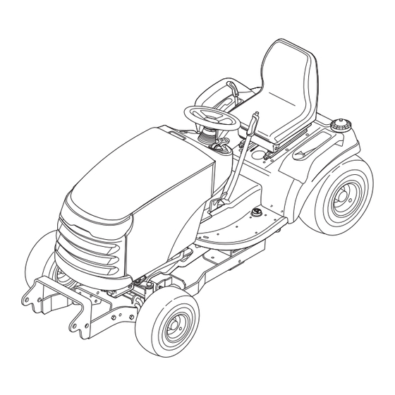
- Page 1 Installation Sub-Frame Hitch Mfg. No. 1695196 Instructions For Prestige / 1800 / 2800, Conquest / 1700 / 2700, & Broadmoor / 1600 / 2600 Series Tractors This kit is required when installing front mounted snowthrowers.
- Page 2 Installation Instructions Sub-Frame Hitch Main Hitch Components (All Applications) Front Hole for Dozer Applications Hydraulic Rear Hole for Snowthrower Applications Lift Early Manual Lift Only (See Instructions) Figure 1. Contents...
- Page 3 Installation Instructions Sub-Frame Hitch Part No. Qty. Description 1723292A SHAFT & HOOK ASSY 1653768A CLAMP, Support 1931335 CARRIAGE BOLT, 5/16-18 x 1 1919381 WASHER, 11/32 1917356 LOCKWASHER, 5/16 1917372 NUT, 5/16-18 105249 PIN, Round Head, 3/8 x 2-3/8 1724025 LIFT LEVER ASSY. 2176012 SAFETY CLIP 1722946...
-
Page 4: Initial Assembly
Installation Instructions Sub-Frame Hitch NOTE: Please read through these instructions and the Assemble Push Bar Latch instructions of any other attachments before beginning 1. Attach Push Bar Latch (B, Figure 3), to hitch. Secure installation. with four .31-16 x 1 bolts (A), and four .38-16 flange nuts (C). -
Page 5: Initial Installation
Installation Instructions Sub-Frame Hitch INITIAL INSTALLATION Snowthrower & Dozer Manual Lift Models Applications LIFT LINK - EARLY VS. LATER The early model lift link (A, Figure 5) was used on early production Conquest/1700/2700 Series tractors. It must be replaced with the later model lift link (B) included with this attachment. -
Page 6: Install Hitch
Installation Instructions Sub-Frame Hitch Figure 8. Install Hitch A. J-Hooks D. Hook B. Hitch Rod E. Clamp Plate C. Hitch Rod Install Hitch 5. Push the clamp plate (D) backwards until it is snug against the lift shaft. Tighten the clamp plate hard- 1. -
Page 7: Install Lift Rod
Installation Instructions Sub-Frame Hitch Figure 10. Install Lift Rod - All Models A. Lift Lever B. Lift Rod Figure 9. Install Lift Lever C. Clip A. Lift Lever B. Lift Shaft C. Safety Clip D. Clevis Pin Install Lift Rod 1. -
Page 8: Normal Installation
Installation Instructions Sub-Frame Hitch Snowthrower Position A. Hitch Rod B. Hitch Rod C. Lift Lever Extension D. Lift Link (Manual) E. Pressure Lock Plate (Hydraulic) F. Hook Figure 11. Normal Installation & Removal REMOVAL NORMAL INSTALLATION NOTE: After removing components, reinstall the clevis 1. -
Page 9: Lift Variations When Using Attachments
Installation Instructions Sub-Frame Hitch Snowthrower Snowthrower & Dozer & Dozer Applications Applications Mower Mower Applications Applications Figure 12. Lift Lock Plate - Hydraulic Lift Models Figure 13. Lift Link - Manual Lift Models A. Lift Cylinder A. Pin B. Flat Head Pin (Original) B. - Page 10 Installation Instructions Sub-Frame Hitch NOTES M A N U F A C T U R I N G , I N C . Form No. 1733911-04 Rev. 01/2007 500 N Spring Street / PO Box 997 © 2007 Briggs & Stratton, Inc. All Rights Reserved Port Washington, WI 53074-0997 USA TP 200-4417-04-AT-SMAN...
Need help?
Do you have a question about the 1695196 and is the answer not in the manual?
Questions and answers